Page 1311 of 1500
TRACTION CONTROL SYSTEM (TCL) DIAGNOSIS
TRACTION CONTROL SYSTEM (TCL)13C-32
STEP 4. Check the harness wire between ABS/TCL-ECU
connector A-02 terminal 21 and TCL switch connector
C-131 terminal 1 for damage.
Q: Are there harness wires in good condition?
YES : Go to Step 5.
NO : Repair the damaged harness wire. Then go to Step 7.
Page 1312 of 1500
TRACTION CONTROL SYSTEM (TCL) DIAGNOSIS
TRACTION CONTROL SYSTEM (TCL)13C-33
STEP 5. Check the harness wire between TCL switch
connector C-131 terminal 2 and ground for damage.
Q: Is the harness wire in good condition?
YES : Go to Step 6.
NO : Repair the damaged harness wire. Then go to Step 7.
STEP 6. Retest the system
Q: Does TCL system cancel, when the TCL switch is
pushed on?
YES : It can be assumed that this malfunction is intermittent.
(Refer to GROUP 00, How to Use
Troubleshooting/Inspection Service Points
How to
Cope with Intermittent Malfunction P.00-14).
NO : Replace the hydraulic unit (integrated with
ABS/TCL-ECU). (Refer to GROUP 35B
Hydraulic
Unit P.35B-93). Then go to Step 7.
STEP 7. Retest the system
Q: Does TCL system cancel, when the TCL switch is
pushed on?
YES : The procedure is complete.
NO : Return to Step 1.
Page 1327 of 1500

ON-VEHICLE SERVICE
TRACTION CONTROL SYSTEM (TCL)13C-48
To prevent damage to diagnostic tool MB991958, always
turn the ignition switch to the "LOCK" (OFF) position
before connecting or disconnecting diagnostic tool
MB991958.
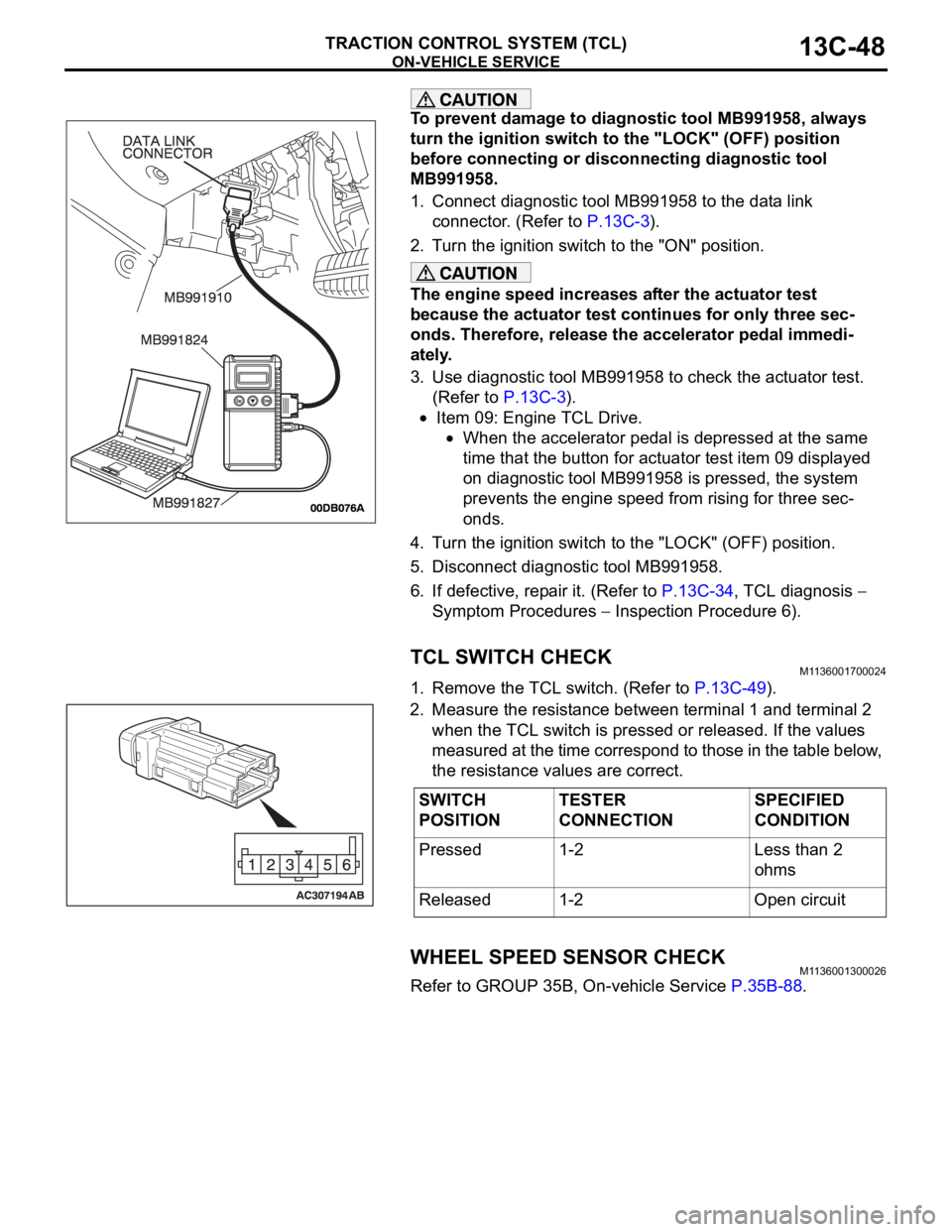
1. Connect diagnostic tool MB991958 to the data link
connector. (Refer to P.13C-3).
2. Turn the ignition switch to the "ON" position.
The engine speed increases after the actuator test
because the actuator test continues for only three sec-
onds. Therefore, release the accelerator pedal immedi-
ately.
3. Use diagnostic tool MB991958 to check the actuator test.
(Refer to P.13C-3).
Item 09: Engine TCL Drive.
When the accelerator pedal is depressed at the same
time that the button for actuator test item 09 displayed
on diagnostic tool MB991958 is pressed, the system
prevents the engine speed from rising for three sec-
onds.
4. Turn the ignition switch to the "LOCK" (OFF) position.
5. Disconnect diagnostic tool MB991958.
6. If defective, repair it. (Refer to P.13C-34, TCL diagnosis
Symptom Procedures
Inspection Procedure 6).
TCL SWITCH CHECKM1136001700024
1. Remove the TCL switch. (Refer to P.13C-49).
2. Measure the resistance between terminal 1 and terminal 2
when the TCL switch is pressed or released. If the values
measured at the time correspond to those in the table below,
the resistance values are correct.
WHEEL SPEED SENSOR CHECKM1136001300026
Refer to GROUP 35B, On-vehicle Service P.35B-88.
SWITCH
POSITIONTESTER
CONNECTIONSPECIFIED
CONDITION
Pressed 1-2 Less than 2
ohms
Released 1-2 Open circuit
Page 1348 of 1500
AUTO-CRUISE CONTROL
ENGINE AND EMISSION CONTROL17-17
STEP 3. Measure the clutch switch power supply voltage
by backprobing the clutch switch connector C-07 (terminal
1).
(1) Measure the voltage between terminal No. 1 and ground.
Voltage should be battery positive voltage.
Q: Is battery positive voltage (approximately 12 volts)
present?
YES : Go to Step 5.
NO : Then go to Step 4.
STEP 4. Check harness connector C-07 at Clutch switch
for damage, loose or corroded terminals .
Q: Is the harness connector in good condition?
YES : Then go to Step 5.
NO : Repair or replace it. Refer to GROUP 00E, Harness
Connector Inspection 00E-2. Then go to Step 6.
Page 1355 of 1500

AUTO-CRUISE CONTROL
ENGINE AND EMISSION CONTROL17-24
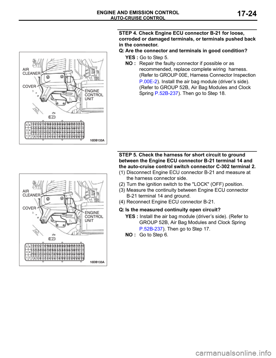
STEP 4. Check Engine ECU connector B-21 for loose,
corroded or damaged terminals, or terminals pushed back
in the connector.
Q: Are the connector and terminals in good condition?
YES : Go to Step 5.
NO : Repair the faulty connector if possible or as
recommended, replace complete wiring harness.
(Refer to GROUP 00E, Harness Connector Inspection
P.00E-2). Install the air bag module (driver’s side).
(Refer to GROUP 52B, Air Bag Modules and Clock
Spring P.52B-237). Then go to Step 18.
STEP 5. Check the harness for short circuit to ground
between the Engine ECU connector B-21 terminal 14 and
the auto-cruise control switch connector C-302 terminal 2.
(1) Disconnect Engine ECU connector B-21 and measure at
the harness connector side.
(2) Turn the ignition switch to the "LOCK" (OFF) position.
(3) Measure the continuity between Engine ECU connector
B-21 terminal 14 and ground.
(4) Reconnect Engine ECU connector B-21.
Q: Is the measured continuity open circuit?
YES : Install the air bag module (driver’s side). (Refer to
GROUP 52B, Air Bag Modules and Clock Spring
P.52B-237). Then go to Step 17.
NO : Go to Step 6.
Page 1356 of 1500
AUTO-CRUISE CONTROL
ENGINE AND EMISSION CONTROL17-25
STEP 6. Check intermediate connector C-29, auto-cruise
control switch connector C-302 and clock spring
connectors C-303 and C-306 for loose, corroded or
damaged terminals, or terminals pushed back in the
connector.
Q: Are the connectors and terminals in good condition?
YES : Go to Step 7.
NO : Repair the faulty connector if possible or as
recommended, replace complete wiring harness.
(Refer to GROUP 00E, Harness Connector Inspection
P.00E-2). Install the air bag module (driver’s side).
(Refer to GROUP 52B, Air Bag Modules and Clock
Spring P.52B-237). Then go to Step 18.
Page 1357 of 1500

AUTO-CRUISE CONTROL
ENGINE AND EMISSION CONTROL17-26
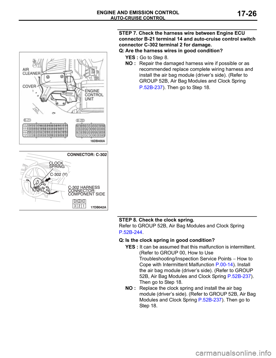
STEP 7. Check the harness wire between Engine ECU
connector B-21 terminal 14 and auto-cruise control switch
connector C-302 terminal 2 for damage.
Q: Are the harness wires in good condition?
YES : Go to Step 8.
NO : Repair the damaged harness wire if possible or as
recommended replace complete wiring harness and
install the air bag module (driver’s side). (Refer to
GROUP 52B, Air Bag Modules and Clock Spring
P.52B-237). Then go to Step 18.
STEP 8. Check the clock spring.
Refer to GROUP 52B, Air Bag Modules and Clock Spring
P.52B-244.
Q: Is the clock spring in good condition?
YES : It can be assumed that this malfunction is intermittent.
(Refer to GROUP 00, How to Use
Troubleshooting/Inspection Service Points
How to
Cope with Intermittent Malfunction P.00-14). Install
the air bag module (driver’s side). (Refer to GROUP
52B, Air Bag Modules and Clock Spring P.52B-237).
Then go to Step 18.
NO : Replace the clock spring and install the air bag
module (driver’s side). (Refer to GROUP 52B, Air Bag
Modules and Clock Spring P.52B-237). Then go to
Step 18.
Page 1359 of 1500
AUTO-CRUISE CONTROL
ENGINE AND EMISSION CONTROL17-28
STEP 11. Check Engine ECU connector B-21 for loose,
corroded or damaged terminals, or terminals pushed back
in the connector.
Q: Are the connector and terminals in good condition?
YES : Install the air bag module (driver’s side). (Refer to
GROUP 52B, Air Bag Modules and Clock Spring
P.52B-237). Then go to Step 17.
NO : Repair the faulty connector if possible, or as
recommended, replace complete wiring harness.
(Refer to GROUP 00E, Harness Connector Inspection
P.00E-2). Install the air bag module (driver’s side).
(Refer to GROUP 52B, Air Bag Modules and Clock
Spring P.52B-237). Then go to Step 18.