Page 1224 of 1500

HOW TO USE THIS MANUAL
GENERAL00-3
HOW TO USE THIS MANUALM1001000100897
MAINTENANCE, REPAIR AND
SERVICING EXPLANATIONS
This manual provides explanations, etc. concerning
procedures for the inspection, maintenance, repair
and servicing of the subject model. Unless otherwise
specified, each service procedure covers all models.
Procedures covering specific models are identified
by the model codes, or similar designation (engine
type, transaxle type, etc). A description of these des-
ignations is covered in this manual under "VEHICLE
IDENTIFICATION."
.
ON-VEHICLE SERVICE
The "ON-VEHICLE SERVICE" section has proce-
dures for performing inspections and adjustments of
particularly important components. These proce-
dures are done with regard to maintenance and ser-
vicing, but other inspections (looseness, play,
cracking, damage, etc.) must also be performed.
.
SERVICE PROCEDURES
The service steps are arranged in numerical order.
Attention to be paid in performing vehicle service are
described in detail in SERVICE POINTS.
DEFINITION OF TERMS
.
STANDARD VALUE
Indicates the value used as the standard for judging
whether or not a part or adjustment is correct.
.
LIMIT
Shows the maximum or minimum value for judging
whether or not a part or adjustment is acceptable.
.
REFERENCE VALUE
Indicates the adjustment value prior to starting the
work (presented in order to facilitate assembly and
adjustment procedures, and so they can be com-
pleted in a shorter time).
.
DANGER, WARNING, AND CAUTION
DANGER, WARNING, and CAUTION call special
attention to a necessary action or to an action that
must be avoided. The differences among DANGER,
WARNING, and CAUTION are as follows:
If a DANGER is not followed, the result is severe
bodily harm or even death.
If a WARNING is not followed, the result could be
bodily injury.
If a CAUTION is not followed, the result could be
damage to the vehicle, vehicle components or
service equipment.
TIGHTENING TORQUE INDICATION
The tightening torque indicates a median and its tol-
erance by a unit of N
m (in-lb.) or Nm (ft.-lb.). For
fasteners with no assigned torque value, refer to
P.00-32.
SPECIAL TOOL NOTE
Only MMC special tool part numbers are called out in
the repair sections of this manual. Please refer to the
special tool cross-reference chart located at the
beginning of each group, for the special tool number
that is available in your market.
ABBREVIATIONS
The following abbreviations are used in this manual
for classification of model types:
A/T:Automatic transaxle, or models equipped with
automatic transaxle.
MPI: Multipoint fuel injection, or engines equipped
with multiport fuel injection.
A/C: Air conditioning.
3.8L engine: 3.8 litre <6G75> engine, or a model
equipped with such an engine.
ABS: Anti-lock Braking System
TCL: Traction Control System
ECU: Electronic Control Unit
V.C.I.: Vehicle Communication Interface
SWS: Simplified Wiring System
CAN: Controller Area Network
M/T: Manual Transmission
SRS: Supplemental Restraint System
Page 1229 of 1500

HOW TO USE TROUBLESHOOTING/INSPECTION SERVICE POINTS
GENERAL00-8
Checks don't have to be carried out in the order
given in the chart.
3. If voltage readings differ from normal condition
values, check related sensors, actuators, and
wiring. Replace or repair as needed.
4. After repair or replacement, recheck with the
voltmeter to confirm that the repair has corrected
the problem.
.
TERMINAL RESISTANCE AND
CONTINUITY CHECKS
1. Turn the ignition switch to the “LOCK” (OFF)
position.
2. Disconnect the ECU connector.
If resistance and continuity checks are per-
formed on the wrong terminals, damage to the
vehicle wiring, sensors, ECU, and/or ohmmeter
may occur. Use care to prevent this!
3. Measure the resistance and check for continuity
between the terminals of the ENGIN-ECU check
harness MB992044 connector while referring to
the check chart.
NOTE: Checks don't have to be carried out in the
order given in the chart.
4. If the ohmmeter shows any deviation from the
Normal Condition value, check the corresponding
sensor, actuator and related electrical wiring, then
repair or replace.
5. After repair or replacement, recheck with the
ohmmeter to confirm that the repair has corrected
the problem.
10. INSPECTION PROCEDURES USING
AN OSCILLOSCOPE
When there are inspection procedures using an
oscilloscope, these are listed.
Page 1256 of 1500
RECOMMENDED LUBRICANTS AND LUBRICANT CAPACITIES TABLE
GENERAL00-35
RECOMMENDED LUBRICANTS AND LUBRICANT
CAPACITIES TABLE
M1001001300504
RECOMMENDED LUBRICANTS
LUBRICANT CAPACITY TABLE
<3.8L ENGINE>LUBRICANT SPECIFICATION
Engine oil Engine oils conforming to ACEA A1, A2 or A3 and
AP1 SG or higher
AutomaticTransmission fluid Genuine Mitsubishi Motors ATF-SP III
Manual Transmission fluid Genuine Mitsubishi Motors MTF
Power steering fluid ATF DEXRON III or DEXRON II
Brakes fluid Conforming to DOT 3 or DOT 4
Engine coolant Genuine Mitsubishi Motors coolant
Refrigerant (air conditioning) HFC-134a
DESCRIPTION SPECIFICATION
Engine oil (Litres) Oil pan (excluding oil filter) 4.0
Oil filter 0.3
Engine coolant (Litres) 8.7
Automatic Transmission fluid (Litres) 8.4
Manual Transmission fluid (Litres) 2.8
Power steering fluid (Litres) 1.2
Fuel tank (Litres) 67.0
Washer fluid (Litres) 5.0
Refrigerant (air conditioning) (grams) 435g - 475g
Page 1258 of 1500

MAINTENANCE SERVICE
GENERAL00-37
MAINTENANCE SERVICE
1. FUEL SYSTEM (TANK, PIPE LINE AND
CONNECTION, AND FUEL TANK FILLER TUBE
CAP) (CHECK FOR LEAKS)
M1001001600312
Check for damage or leakage in the fuel lines and connections.
2. FUEL HOSES (CHECK CONDITION)M1001001700308
1. Inspect the surface of fuel hoses for heat and mechanical
damage. Hard and brittle rubber, cracking, tears, cuts,
abrasions and excessive swelling indicate deterioration of
the rubber.
2. If the fabric casing of the rubber hose is exposed by cracks
and abrasions in the fuel system, the hose should be
replaced.
3. AIR CLEANER FILTER (REPLACE)M1001001800338
The air cleaner element will become dirty during use, reducing
its effectiveness. Replace it with a new one.
REPLACEMENT OF AIR CLEANER ELEMENT
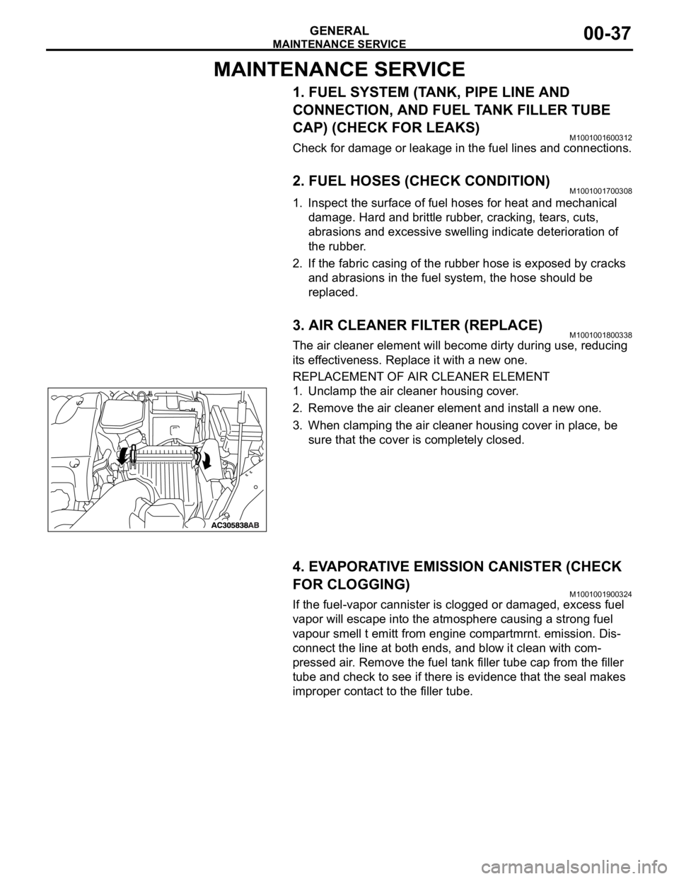
1. Unclamp the air cleaner housing cover.
2. Remove the air cleaner element and install a new one.
3. When clamping the air cleaner housing cover in place, be
sure that the cover is completely closed.
4. EVAPORATIVE EMISSION CANISTER (CHECK
FOR CLOGGING)
M1001001900324
If the fuel-vapor cannister is clogged or damaged, excess fuel
vapor will escape into the atmosphere causing a strong fuel
vapour smell t emitt from engine compartmrnt. emission. Dis-
connect the line at both ends, and blow it clean with com-
pressed air. Remove the fuel tank filler tube cap from the filler
tube and check to see if there is evidence that the seal makes
improper contact to the filler tube.
Page 1260 of 1500
MAINTENANCE SERVICE
GENERAL00-39
7. DRIVE BELTS (FOR ALTERNATOR, POWER
STEERING PUMP AND AIR CONDITIONING)
(CHECK)
M1001008700031
ALTERNATOR DRIVE BELT TENSION CHECK
<3.8L ENGINE>
.
WHEN USING DIAGNOSTIC TOOL (MUT-III)
Required Special Tools:
MB991668: Belt Tension Meter Set
Diagnostic Tool (MUT-III)
MB991824: Vehicle Communication Interface (V.C.I.)
MB991910: MUT-III Main Harness A (BLUE)
To prevent damage to DIAGNOSTIC TOOL (MUT-III), always
turn the ignition switch to the "LOCK" (OFF) position
before connecting or disconnecting.
1. Connect Belt Tension Meter Set (MB991668) to V.C.I
(MB991824).
2. Connect MUT-III Main Harness A (BLUE) (MB991910) to
V.C.I (MB991824).
3. Connect MUT-III Main Harness A (BLUE) (MB991910) to the
data link connector.
4. Turn the ignition switch to the "ON" position and select "Belt
Tension" from the menu V.C.I (MB991824) screen.
Page 1267 of 1500
![MITSUBISHI 380 2005 Workshop Manual MAINTENANCE SERVICE
GENERAL00-46
NOTE: If it takes some amount of time until the transmission
fluid reaches its normal operating temperature [70
80C
(158
176F)], check the transmission fluid lev MITSUBISHI 380 2005 Workshop Manual MAINTENANCE SERVICE
GENERAL00-46
NOTE: If it takes some amount of time until the transmission
fluid reaches its normal operating temperature [70
80C
(158
176F)], check the transmission fluid lev](/manual-img/19/57086/w960_57086-1266.png)
MAINTENANCE SERVICE
GENERAL00-46
NOTE: If it takes some amount of time until the transmission
fluid reaches its normal operating temperature [70
80C
(158
176F)], check the transmission fluid level by refer-
ring to the left diagram.
2. Park the vehicle on a level surface.
3. Move the selector lever through all positions to fill the torque
converter and the hydraulic circuits with fluid, and then move
the selector lever to the "N" position.
4. After wiping off any dirt around the dipstick, remove the
dipstick and check the condition of the transmission fluid.
NOTE: If the transmission fluid smells as if it is burnt, it
means that the transmission fluid has been contaminated by
fine particles from the bushings and friction materials. Tran-
saxle overhaul and cooler line flushing may be necessary.
5. Check transmission fluid level is at the "HOT" mark on the
dipstick. If the transmission fluid level is less than this, add
DIAMOND ATF SP III until the level reaches the "HOT"
mark.
NOTE: If the transmission fluid level is too low, the oil pump
will draw in air along with the transmission fluid, which will
cause to form bubbles. If the transmission fluid level is too
high, rotating components inside the transaxle will churn the
fluid and air into a foamy liquid. Both conditions (level too
low or too high) will cause the hydraulic pressure to drop,
which will result in late shifting and slipping of the clutches
and brakes.
NOTE: In either case, air bubbles can interfere with normal
valve, clutch, and brake operation. Also, foaming can cause
transmission fluid to escape from the transaxle vent where it
may be mistaken for a leak.
Page 1301 of 1500

TRACTION CONTROL SYSTEM (TCL) DIAGNOSIS
TRACTION CONTROL SYSTEM (TCL)13C-22
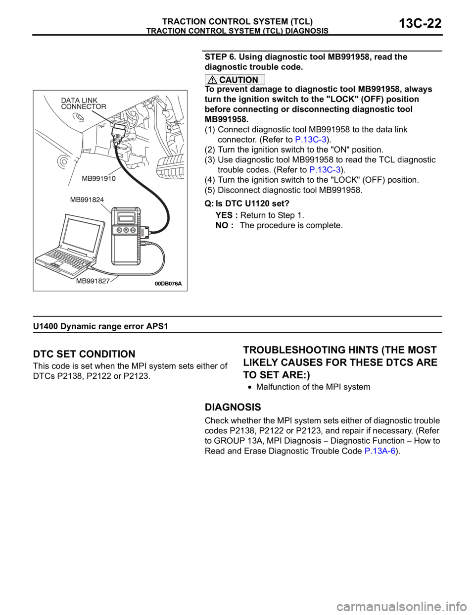
STEP 6. Using diagnostic tool MB991958, read the
diagnostic trouble code.
To prevent damage to diagnostic tool MB991958, always
turn the ignition switch to the "LOCK" (OFF) position
before connecting or disconnecting diagnostic tool
MB991958.
(1) Connect diagnostic tool MB991958 to the data link
connector. (Refer to P.13C-3).
(2) Turn the ignition switch to the "ON" position.
(3) Use diagnostic tool MB991958 to read the TCL diagnostic
trouble codes. (Refer to P.13C-3).
(4) Turn the ignition switch to the "LOCK" (OFF) position.
(5) Disconnect diagnostic tool MB991958.
Q: Is DTC U1120 set?
YES : Return to Step 1.
NO : The procedure is complete.
U1400 Dynamic range error APS1
.
DTC SET CONDITION
This code is set when the MPI system sets either of
DTCs P2138, P2122 or P2123.
.
TROUBLESHOOTING HINTS (THE MOST
LIKELY CAUSES FOR THESE DTCS ARE
TO SET ARE:)
Malfunction of the MPI system
DIAGNOSIS
Check whether the MPI system sets either of diagnostic trouble
codes P2138, P2122 or P2123, and repair if necessary. (Refer
to GROUP 13A, MPI Diagnosis
Diagnostic Function How to
Read and Erase Diagnostic Trouble Code P.13A-6).
Page 1310 of 1500
TRACTION CONTROL SYSTEM (TCL) DIAGNOSIS
TRACTION CONTROL SYSTEM (TCL)13C-31
STEP 3. Check ABS/TCL-ECU connector A-02,
intermediate connector C-29 and TCL switch connectors
C-131 for loose, corroded or damaged terminals, or
terminals pushed back in the connector.
Q: Are there connectors and terminals in good condition?
YES : Go to Step 4.
NO : Repair or replace the faulty connector. (Refer to
GROUP 00E, Harness Connector Inspection
P.00E-2). Then go to Step 7.