2005 MITSUBISHI 380 air condition
[x] Cancel search: air conditionPage 1091 of 1500
DOOR
BODY42-24
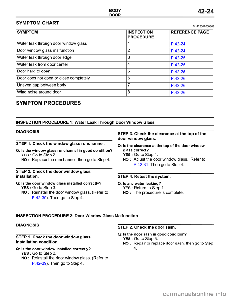
SYMPTOM CHARTM1423007000303
SYMPTOM PROCEDURES
INSPECTION PROCEDURE 1: Water Leak Through Door Window Glass
DIAGNOSIS
STEP 1. Check the window glass runchannel.
Q: Is the window glass runchannel in good condition?
YES :
Go to Step 2.
NO : Replace the runchannel, then go to Step 4.
STEP 2. Check the door window glass
installation.
Q: Is the door window glass installed correctly?
YES :
Go to Step 3.
NO : Reinstall the door window glass. (Refer to
P.42-39). Then go to Step 4.
STEP 3. Check the clearance at the top of the
door window glass.
Q: Is the clearance at the top of the door window
glass correct?
YES :
Go to Step 4.
NO : Adjust the door window glass. Refer to
P.42-31. Then go to Step 4.
STEP 4. Retest the system.
Q: Is any water leaking?
YES :
Return to Step 1.
NO : The procedure is complete.
INSPECTION PROCEDURE 2: Door Window Glass Malfunction
DIAGNOSIS
STEP 1. Check the door window glass
installation condition.
Q: Is the door window installed correctly?
YES :
Go to Step 2.
NO : Reinstall the door window glass. (Refer to
P.42-39). Then go to Step 4.
STEP 2. Check the door sash.
Q: Is the door sash in good condition?
YES :
Go to Step 3.
NO : Repair or replace door sash, then go to Step
4. SYMPTOM INSPECTION
PROCEDUREREFERENCE PAGE
Water leak through door window glass 1
P.42-24
Door window glass malfunction 2
P.42-24
Water leak through door edge 3
P.42-25
Water leak from door center 4
P.42-25
Door hard to open 5
P.42-25
Door does not open or close completely 6
P.42-26
Uneven gap between body 7
P.42-26
Wind noise around door 8
P.42-26
Page 1092 of 1500
DOOR
BODY42-25
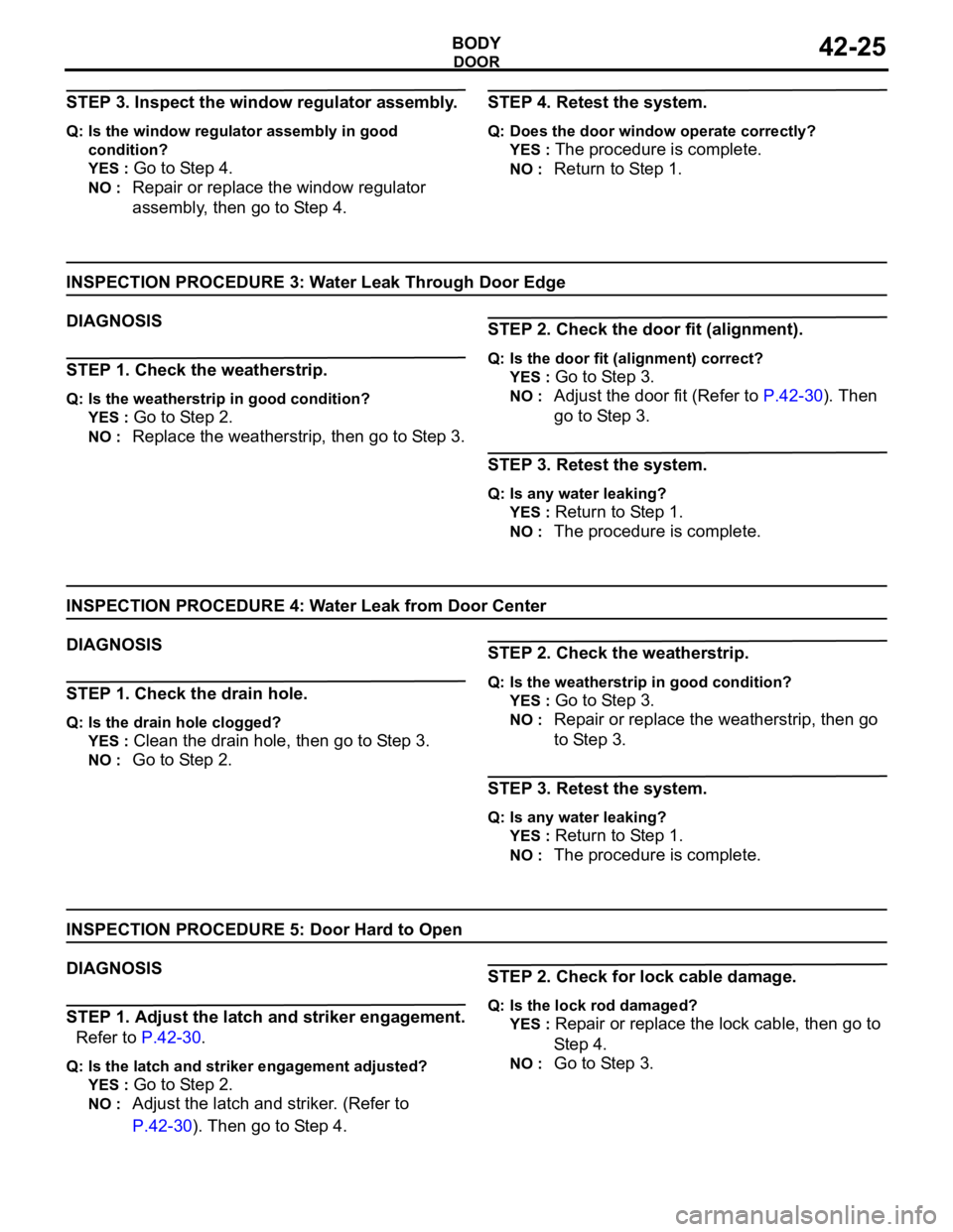
STEP 3. Inspect the window regulator assembly.
Q: Is the window regulator assembly in good
condition?
YES :
Go to Step 4.
NO : Repair or replace the window regulator
assembly, then go to Step 4.
STEP 4. Retest the system.
Q: Does the door window operate correctly?
YES :
The procedure is complete.
NO : Return to Step 1.
INSPECTION PROCEDURE 3: Water Leak Through Door Edge
DIAGNOSIS
STEP 1. Check the weatherstrip.
Q: Is the weatherstrip in good condition?
YES :
Go to Step 2.
NO : Replace the weatherstrip, then go to Step 3.
STEP 2. Check the door fit (alignment).
Q: Is the door fit (alignment) correct?
YES :
Go to Step 3.
NO : Adjust the door fit (Refer to P.42-30). Then
go to Step 3.
STEP 3. Retest the system.
Q: Is any water leaking?
YES :
Return to Step 1.
NO : The procedure is complete.
INSPECTION PROCEDURE 4: Water Leak from Door Center
DIAGNOSIS
STEP 1. Check the drain hole.
Q: Is the drain hole clogged?
YES :
Clean the drain hole, then go to Step 3.
NO : Go to Step 2.
STEP 2. Check the weatherstrip.
Q: Is the weatherstrip in good condition?
YES :
Go to Step 3.
NO : Repair or replace the weatherstrip, then go
to Step 3.
STEP 3. Retest the system.
Q: Is any water leaking?
YES :
Return to Step 1.
NO : The procedure is complete.
INSPECTION PROCEDURE 5: Door Hard to Open
DIAGNOSIS
STEP 1. Adjust the latch and striker engagement.
Refer to P.42-30.
Q: Is the latch and striker engagement adjusted?
YES :
Go to Step 2.
NO : Adjust the latch and striker. (Refer to
P.42-30). Then go to Step 4.
STEP 2. Check for lock cable damage.
Q: Is the lock rod damaged?
YES :
Repair or replace the lock cable, then go to
St e p 4.
NO : Go to Step 3.
Page 1093 of 1500
DOOR
BODY42-26
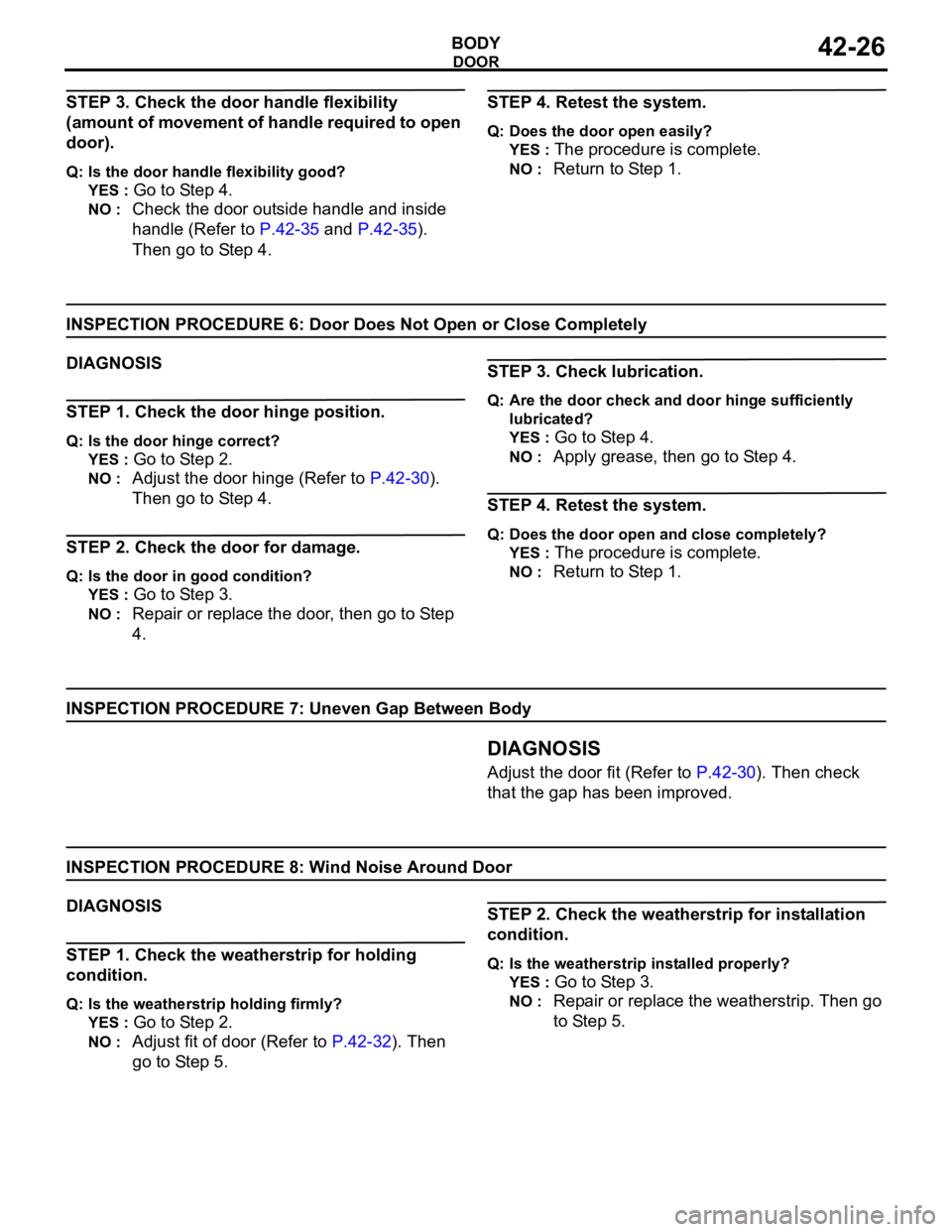
STEP 3. Check the door handle flexibility
(amount of movement of handle required to open
door).
Q: Is the door handle flexibility good?
YES :
Go to Step 4.
NO : Check the door outside handle and inside
handle (Refer to P.42-35 and P.42-35).
Then go to Step 4.
STEP 4. Retest the system.
Q: Does the door open easily?
YES :
The procedure is complete.
NO : Return to Step 1.
INSPECTION PROCEDURE 6: Door Does Not Open or Close Completely
DIAGNOSIS
STEP 1. Check the door hinge position.
Q: Is the door hinge correct?
YES :
Go to Step 2.
NO : Adjust the door hinge (Refer to P.42-30).
Then go to Step 4.
STEP 2. Check the door for damage.
Q: Is the door in good condition?
YES :
Go to Step 3.
NO : Repair or replace the door, then go to Step
4.
STEP 3. Check lubrication.
Q: Are the door check and door hinge sufficiently
lubricated?
YES :
Go to Step 4.
NO : Apply grease, then go to Step 4.
STEP 4. Retest the system.
Q: Does the door open and close completely?
YES :
The procedure is complete.
NO : Return to Step 1.
INSPECTION PROCEDURE 7: Uneven Gap Between Body
.DIAGNOSIS
Adjust the door fit (Refer to P.42-30). Then check
that the gap has been improved.
INSPECTION PROCEDURE 8: Wind Noise Around Door
DIAGNOSIS
STEP 1. Check the weatherstrip for holding
condition.
Q: Is the weatherstrip holding firmly?
YES :
Go to Step 2.
NO : Adjust fit of door (Refer to P.42-32). Then
go to Step 5.
STEP 2. Check the weatherstrip for installation
condition.
Q: Is the weatherstrip installed properly?
YES :
Go to Step 3.
NO : Repair or replace the weatherstrip. Then go
to Step 5.
Page 1099 of 1500
DOOR
BODY42-32
GLASS SLIDING MECHANISM CHECK AND
ADJUSTMENT
M1429000900109
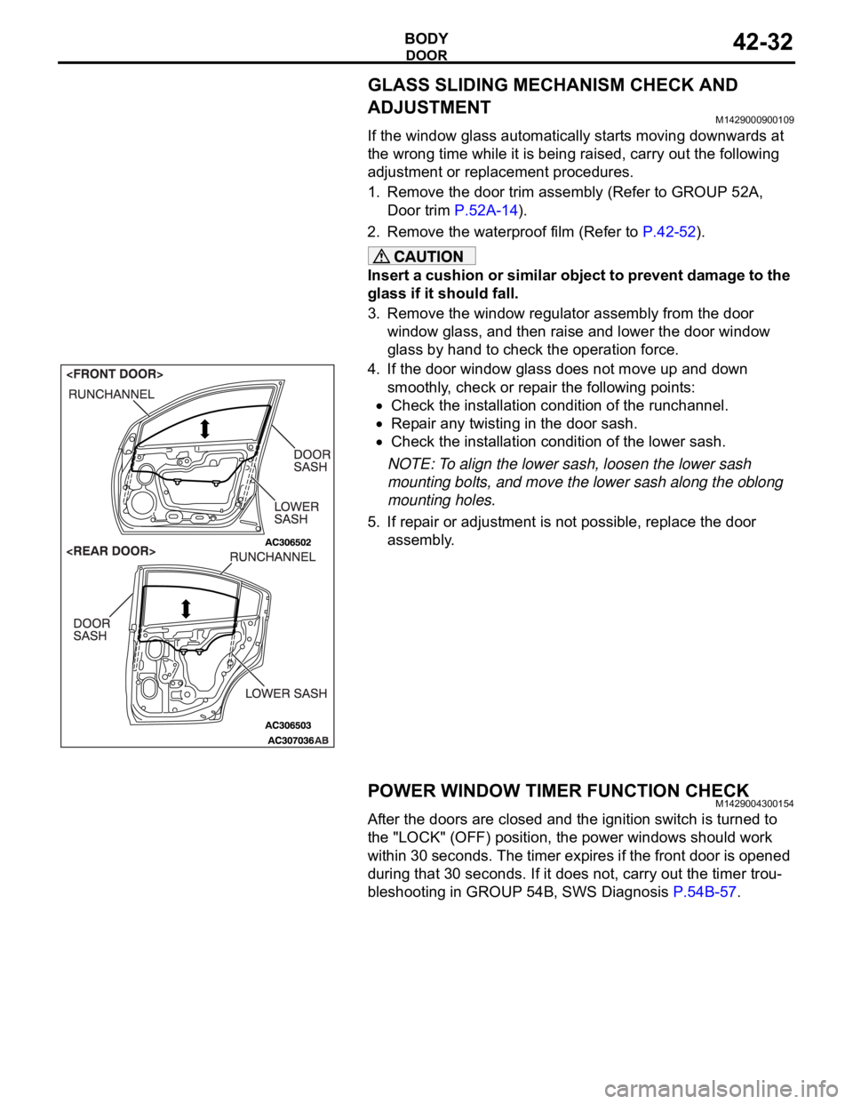
If the window glass automatically starts moving downwards at
the wrong time while it is being raised, carry out the following
adjustment or replacement procedures.
1. Remove the door trim assembly (Refer to GROUP 52A,
Door trim P.52A-14).
2. Remove the waterproof film (Refer to P.42-52).
Insert a cushion or similar object to prevent damage to the
glass if it should fall.
3. Remove the window regulator assembly from the door
window glass, and then raise and lower the door window
glass by hand to check the operation force.
4. If the door window glass does not move up and down
smoothly, check or repair the following points:
Check the installation condition of the runchannel.
Repair any twisting in the door sash.
Check the installation condition of the lower sash.
NOTE: To align the lower sash, loosen the lower sash
mounting bolts, and move the lower sash along the oblong
mounting holes.
5. If repair or adjustment is not possible, replace the door
assembly.
POWER WINDOW TIMER FUNCTION CHECKM1429004300154
After the doors are closed and the ignition switch is turned to
the "LOCK" (OFF) position, the power windows should work
within 30 seconds. The timer expires if the front door is opened
during that 30 seconds. If it does not, carry out the timer trou-
bleshooting in GROUP 54B, SWS Diagnosis P.54B-57.
Page 1170 of 1500
BASIC BRAKE SYSTEM DIAGNOSIS
BASIC BRAKE SYSTEM35A-5
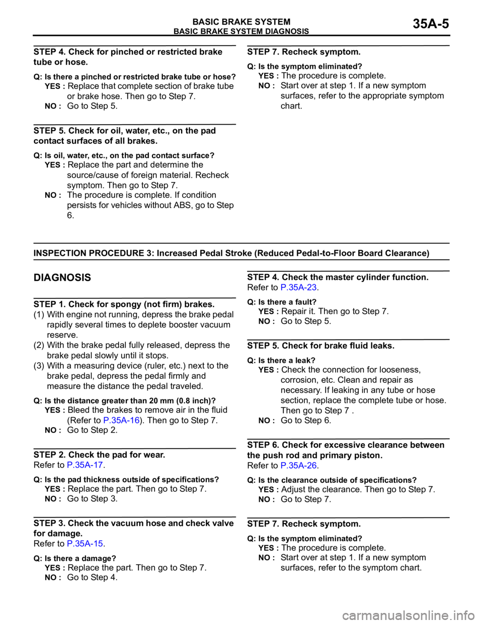
STEP 4. Check for pinched or restricted brake
tube or hose.
Q: Is there a pinched or restricted brake tube or hose?
YES :
Replace that complete section of brake tube
or brake hose. Then go to Step 7.
NO : Go to Step 5.
STEP 5. Check for oil, water, etc., on the pad
contact surfaces of all brakes.
Q: Is oil, water, etc., on the pad contact surface?
YES :
Replace the part and determine the
source/cause of foreign material. Recheck
symptom. Then go to Step 7.
NO : The procedure is complete. If condition
persists for vehicles without ABS, go to Step
6.
STEP 7. Recheck symptom.
Q: Is the symptom eliminated?
YES :
The procedure is complete.
NO : Start over at step 1. If a new symptom
surfaces, refer to the appropriate symptom
chart.
INSPECTION PROCEDURE 3: Increased Pedal Stroke (Reduced Pedal-to-Floor Board Clearance)
.
DIAGNOSIS
STEP 1. Check for spongy (not firm) brakes.
(1) With engine not running, depress the brake pedal
rapidly several times to deplete booster vacuum
reserve.
(2) With the brake pedal fully released, depress the
brake pedal slowly until it stops.
(3) With a measuring device (ruler, etc.) next to the
brake pedal, depress the pedal firmly and
measure the distance the pedal traveled.
Q: Is the distance greater than 20 mm (0.8 inch)?
YES :
Bleed the brakes to remove air in the fluid
(Refer to P.35A-16). Then go to Step 7.
NO : Go to Step 2.
STEP 2. Check the pad for wear.
Refer to P.35A-17.
Q: Is the pad thickness outside of specifications?
YES :
Replace the part. Then go to Step 7.
NO : Go to Step 3.
STEP 3. Check the vacuum hose and check valve
for damage.
Refer to P.35A-15.
Q: Is there a damage?
YES :
Replace the part. Then go to Step 7.
NO : Go to Step 4.
STEP 4. Check the master cylinder function.
Refer to P.35A-23.
Q: Is there a fault?
YES :
Repair it. Then go to Step 7.
NO : Go to Step 5.
STEP 5. Check for brake fluid leaks.
Q: Is there a leak?
YES :
Check the connection for looseness,
corrosion, etc. Clean and repair as
necessary. If leaking in any tube or hose
section, replace the complete tube or hose.
Then go to Step 7 .
NO : Go to Step 6.
STEP 6. Check for excessive clearance between
the push rod and primary piston.
Refer to P.35A-26.
Q: Is the clearance outside of specifications?
YES :
Adjust the clearance. Then go to Step 7.
NO : Go to Step 7.
STEP 7. Recheck symptom.
Q: Is the symptom eliminated?
YES :
The procedure is complete.
NO : Start over at step 1. If a new symptom
surfaces, refer to the symptom chart.
Page 1172 of 1500
BASIC BRAKE SYSTEM DIAGNOSIS
BASIC BRAKE SYSTEM35A-7
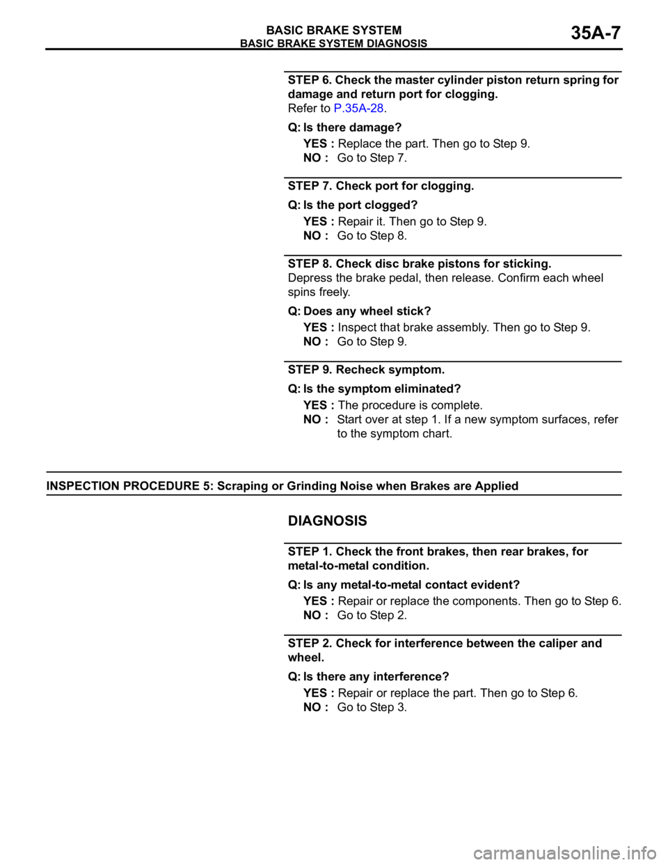
STEP 6. Check the master cylinder piston return spring for
damage and return port for clogging.
Refer to P.35A-28.
Q: Is there damage?
YES : Replace the part. Then go to Step 9.
NO : Go to Step 7.
STEP 7. Check port for clogging.
Q: Is the port clogged?
YES : Repair it. Then go to Step 9.
NO : Go to Step 8.
STEP 8. Check disc brake pistons for sticking.
Depress the brake pedal, then release. Confirm each wheel
spins freely.
Q: Does any wheel stick?
YES : Inspect that brake assembly. Then go to Step 9.
NO : Go to Step 9.
STEP 9. Recheck symptom.
Q: Is the symptom eliminated?
YES : The procedure is complete.
NO : Start over at step 1. If a new symptom surfaces, refer
to the symptom chart.
INSPECTION PROCEDURE 5: Scraping or Grinding Noise when Brakes are Applied
.
DIAGNOSIS
STEP 1. Check the front brakes, then rear brakes, for
metal-to-metal condition.
Q: Is any metal-to-metal contact evident?
YES : Repair or replace the components. Then go to Step 6.
NO : Go to Step 2.
STEP 2. Check for interference between the caliper and
wheel.
Q: Is there any interference?
YES : Repair or replace the part. Then go to Step 6.
NO : Go to Step 3.
Page 1180 of 1500
ON-VEHICLE SERVICE
BASIC BRAKE SYSTEM35A-15
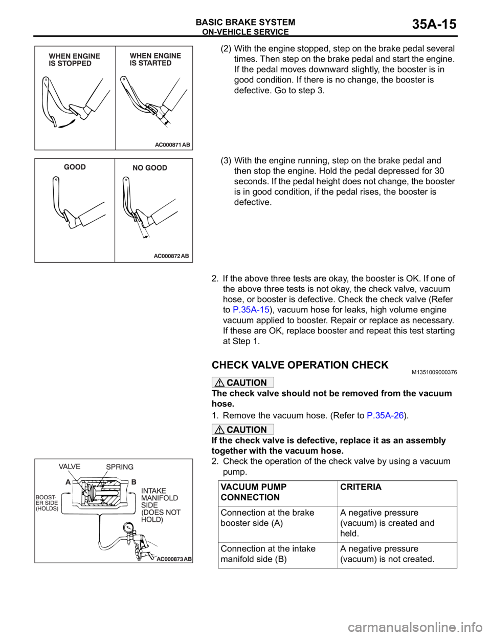
(2) With the engine stopped, step on the brake pedal several
times. Then step on the brake pedal and start the engine.
If the pedal moves downward slightly, the booster is in
good condition. If there is no change, the booster is
defective. Go to step 3.
(3) With the engine running, step on the brake pedal and
then stop the engine. Hold the pedal depressed for 30
seconds. If the pedal height does not change, the booster
is in good condition, if the pedal rises, the booster is
defective.
2. If the above three tests are okay, the booster is OK. If one of
the above three tests is not okay, the check valve, vacuum
hose, or booster is defective. Check the check valve (Refer
to P.35A-15), vacuum hose for leaks, high volume engine
vacuum applied to booster. Repair or replace as necessary.
If these are OK, replace booster and repeat this test starting
at Step 1.
CHECK VALVE OPERATION CHECKM1351009000376
The check valve should not be removed from the vacuum
hose.
1. Remove the vacuum hose. (Refer to P.35A-26).
If the check valve is defective, replace it as an assembly
together with the vacuum hose.
2. Check the operation of the check valve by using a vacuum
pump.
VACUUM PUMP
CONNECTIONCRITERIA
Connection at the brake
booster side (A)A negative pressure
(vacuum) is created and
held.
Connection at the intake
manifold side (B)A negative pressure
(vacuum) is not created.
Page 1223 of 1500
GENERAL00-2
MAINTENANCE SERVICE . . . . . . . .00-37
1. FUEL SYSTEM (TANK, PIPE LINE AND
CONNECTION, AND FUEL TANK FILLER
TUBE CAP) (CHECK FOR LEAKS) . . . . . . 00-37
2. FUEL HOSES (CHECK CONDITION) . . 00-37
3. AIR CLEANER FILTER (REPLACE). . . . 00-37
4. EVAPORATIVE EMISSION SYSTEM
(EXCEPT EVAPORATIVE EMISSION
CANISTER) (CHECK FOR CLOGGING) . . 00-37
5. SPARK PLUGS (REPLACE). . . . . . . . . . 00-38
7. TIMING BELT (REPLACE) . . . . . . . . . . . 00-38
8. DRIVE BELTS (FOR ALTERNATOR, POWER
STEERING PUMP AND AIR CONDITIONING)
(CHECK) . . . . . . . . . . . . . . . . . . . . . . . . . . . 00-39
9. EXHAUST SYSTEM (CONNECTIONS
PORTION OF MUFFLER, MUFFLER PIPES
AND CONVERTER HEAT SHIELDS) (CHECK
AND SERVICE AS REQUIRED) . . . . . . . . . 00-44
10. ENGINE OIL (CHANGE) . . . . . . . . . . . . 00-4411. ENGINE OIL FILTER (REPLACE) . . . . 00-44
12. TRANSMISSION FLUID . . . . . . . . . . . . 00-45
13. ENGINE COOLANT (CHANGE) . . . . . . 00-47
14. COOLANT HOSES (RADIATOR HOSE,
HEATER HOSE) (INSPECT). . . . . . . . . . . . 00-49
15. DISC BRAKE PADS, ROTORS
(INSPECT FOR WEAR) . . . . . . . . . . . . . . . 00-49
16. BRAKE HOSES (CHECK FOR
DETERIORATION OR LEAKS) . . . . . . . . . . 00-49
17. BALL JOINT AND STEERING LINKAGE
SEALS (INSPECT FOR GREASE LEAKS
AND DAMAGE) . . . . . . . . . . . . . . . . . . . . . . 00-50
18. DRIVE SHAFT BOOTS (INSPECT FOR
GREASE LEAKS AND DAMAGE) . . . . . . . . 00-50
19. SUSPENSION SYSTEM (INSPECT FOR
LOOSENESS AND DAMAGE) . . . . . . . . . . 00-51
20. SRS AIR BAG (INSPECT FOR SRS
SYSTEM). . . . . . . . . . . . . . . . . . . . . . . . . . . 00-51
21. TYRES (ROTATE). . . . . . . . . . . . . . . . . 00-58