2005 MITSUBISHI 380 air condition
[x] Cancel search: air conditionPage 941 of 1500

ON-VEHICLE SERVICE
ENGINE COOLING14-26
DIAGNOSIS
STEP 1. Check the condenser fan motor.
Condenser fan motor check. (Refer to GROUP 55, Condenser
and Condenser Fan Motor.
Q: Is the condenser fan motor in good condition?
YES : Go to Step 2.
NO : Replace the condenser fan motor, then go to Step 3.
STEP 2. Check the fan controller.
Refer to 29.
Q: Is the fan controller in good condition?
YES : Go to Step 3.
NO : Replace the fan motor and fan controller (Refer to
14-25). Then go to Step 3.
STEP 3. Check the symptoms.
Q: Do the condenser fan operate?
YES : This symptom is complete.
NO : Return to Step 1.
ON-VEHICLE SERVICE
ENGINE COOLANT LEAK CHECKM1141001000333
When pressure testing the cooling system, slowly
release cooling system pressure to avoid getting
burned by hot coolant.
Be sure to completely clean away any moisture from
the places checked.
When the tester is taken out, be careful not to spill any
coolant.
Be careful when installing and removing the tester and
when testing not to deform the filler neck of the radia-
tor.
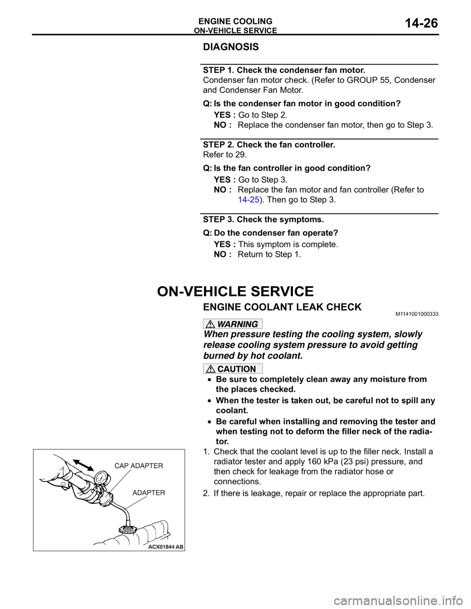
1. Check that the coolant level is up to the filler neck. Install a
radiator tester and apply 160 kPa (23 psi) pressure, and
then check for leakage from the radiator hose or
connections.
2. If there is leakage, repair or replace the appropriate part.
Page 980 of 1500

CHARGING SYSTEM
ENGINE ELECTRICAL16-3
CHARGING SYSTEM DIAGNOSISM1161000700427
TROUBLESHOOTING HINTS
Alternator malfunction light dose not go on when the ignition
switch is turned to ON, before the engine starts.
Check the bulb.
Alternator malfunction light dose not switch off after the engine
starts.
Check the IC voltage regulator inside the
alternatoralternator.
Discharged or overcharged battery.
Check the IC voltage regulator inside the alternator.
The alternator malfunction light illuminates dimly.
Check the diode (inside the combination meter) for a
short-circuit.
TROUBLESHOOTING GUIDE
The charging system troubleshooting guide is shown in the fol-
lowing steps.
STEP 1.
Q: Is the battery in good condition? (Refer to GROUP 54A,
Chassis Electrical
Battery On-vehicle Service
Battery Check P.54A-5.)
YES : Go to Step 2.
NO : Charge or replace the battery.
STEP 2.
Q: Is the alternator drive belt in good condition? (Refer to
GROUP 00, General
Maintenance Service Drive Belts
(For Alternator, Power Steering Pump and Air
Conditioning) (Check) P.00-39.)
YES : Go to Step 3.
NO : Adjust the belt tension or replace the belt.
STEP 3.
Q: Does the alternator malfunction light come on when the
ignition switch is turned on?
YES : Go to Step 4.
NO :
Check the ignition switch. (Refer to GROUP 54A,
Chassis Electrical
Ignition Switch Ignition
Switch
Inspection P.54A-44.)
Check for burnt-out alternator malfunction light.
Check the alternator. (Refer to Charging System
Alternator Assembly
Inspection P.16-17.)
Check the alternator malfunction light-related
circuits.
Page 984 of 1500

CHARGING SYSTEM
ENGINE ELECTRICAL16-7
ON-VEHICLE SERVICE
ALTERNATOR OUTPUT WIRE VOLTAGE DROP TESTM1161000900669
Required Special Tool:
: Diagnostic Tool (MUT-III)
MB991824: V.C.I.
MB991827: MUT-III USB Cable
MB991910: MUT-III Main Harness A
This test determines whether the wiring from the
alternator "B" terminal to the positive battery terminal
(including the fusible link) is in good condition or not:
Battery posts, terminals and related acces-
sories contain lead and lead compounds.
WASH HANDS AFTER HANDLING.
1. Always be sure to check the following before the
test.
Alternator installation
Alternator drive belt tension (Refer to GROUP 00,
General
Maintenance Service Drive Belts
(For Alternator, Power Steering Pump and Air
Conditioning) (Check) P.00-39.)
Fusible link
Abnormal noise from the alternator while the
engine is running.2. Turn the ignition switch to the "LOCK" (OFF)
position.
3. Disconnect the negative battery cable.
4. Connect a clamp-type DC test ammeter with a
range of 0
100 A to the alternator "B" terminal
output wire.
NOTE: The way of disconnecting the alternator
output wire and of connecting the ammeter is pos-
sibly not found the problem that the output current
is dropping due to the insufficient connection
between terminal "B" and the output wire.
5. Connect a digital-type voltmeter between the
alternator "B" terminal and the positive battery
terminal. (Connect the positive lead of the
voltmeter to the "B" terminal, and then connect the
negative lead of the voltmeter to the positive
battery cable.)
6. Reconnect the negative battery cable.
7. Connect an engine tachometer or diagnostic tool.
8. Leave the hood open.
9. Start the engine.
Page 986 of 1500

CHARGING SYSTEM
ENGINE ELECTRICAL16-9
Required Special Tool:
: Diagnostic Tool (MUT-III)
MB991824: V.C.I.
MB991827: MUT-III USB Cable
MB991910: MUT-III Main Harness A
This test determines whether the alternator outputs
normal current. For best results, use a charging sys-
tem tester. If not available, follow the steps below.
Battery posts, terminals and related acces-
sories contain lead and lead compounds.
WASH HANDS AFTER HANDLING.
1. Before the test, always be sure to check the
following.
Alternator installation
Battery (Refer to GROUP 54A, Chassis Electrical
Battery On-vehicle Service Battery Check
P.54A-5.)
NOTE: The battery to be used should be slightly
discharged. The load in a fully-charged battery
will be insufficient and the test may not be able to
be carried out correctly.
Alternator drive belt tension (Refer to GROUP 00,
General
Maintenance Service Drive Belts
(For Alternator, Power Steering Pump and Air
Conditioning) (Check) P.00-39.)
Fusible link
Abnormal noise from the alternator while the
engine is running.
2. Turn the ignition switch to the "LOCK" (OFF)
position.
3. Disconnect the negative battery cable.
Never use clips to connect the wire. Loose
connections (for example, using clips) will
lead to a serious accident because of high
current.
4. Connect a clamp-type DC test ammeter with a
range of 0
120 A to the alternator "B" terminal
output wire.
5. Connect a voltmeter with a range of 0
20 V
between the alternator "B" terminal and ground.
(Connect the positive lead of the voltmeter to the
"B" terminal, and then connect the negative lead
of the voltmeter to ground.)
6. Connect the negative battery cable.
7. Connect an engine tachometer or diagnostic tool.
8. Leave the hood open.9. Check to be sure that the reading on the voltmeter
is equal to the battery positive voltage.
NOTE: If the voltage is 0 V, the cause is probably
an open circuit in the wire or fusible link between
the alternator "B" terminal and the battery positive
terminal or malfunctioning voltmeter.
10.After turning on the headlights, start the engine.
NOTE: Because the current from the battery will
soon drop after the engine is started, step 11
should be carried out as quickly as possible in
order to obtain the maximum current output value.
11.Immediately after setting the headlights to high
beam and turning the heater blower switch to the
highest position, increase the engine speed to
2,500 r/min and read the maximum current output
value displayed on the ammeter.
Limit value: 70 % of nominal current output
NOTE: For the nominal current output, refer to the
Alternator Specifications.
NOTE: The current output value will depend on
the electrical load and the temperature of the
alternator body.
NOTE: If the electrical load is small while testing,
the specified level of current may not be output
even though the alternator is normal. In such
cases, increase the electrical load by leaving the
headlights turned on for some time to discharge
the battery or by using the lighting system in
another vehicle, and then test again.
NOTE: The specified level of current also may not
be output if the temperature of the alternator body
or the ambient temperature is too high. In such
cases, cool the alternator and then test again.
12.The reading on the ammeter should be above the
limit value. If the reading is below the limit value
and the alternator output wire is normal, remove
the alternator from the engine and check the
alternator.
13.Run the engine at idle speed after the test.
14.Turn the ignition switch to the "LOCK" (OFF)
position.
15.Disconnect the engine tachometer or diagnostic
tool.
16.Disconnect the negative battery cable.
17.Disconnect the ammeter and voltmeter .
18.Connect the negative battery cable.
19.Run the engine for 10 minutes at an idle.
Page 987 of 1500

CHARGING SYSTEM
ENGINE ELECTRICAL16-10
REGULATED VOLTAGE TESTM1161001100666
Required Special Tools:
: Diagnostic Tool (MUT-III)
MB991824: V.C.I.
MB991827: MUT-III USB Cable
MB991910: MUT-III Main Harness A
MB998467: Alternator Harness Connector
This test determines whether the voltage regulator is
correctly controlling the alternator output voltage.
Battery posts, terminals and related acces-
sories contain lead and lead compounds.
WASH HANDS AFTER HANDLING.
1. Always be sure to check the following before the
test:
Alternator installation
Check to be sure that the battery installed in the
vehicle is fully charged. (Refer to GROUP 54A,
Chassis Electrical
Battery On-vehicle Service
Battery Check P.54A-5.)
Alternator drive belt tension (Refer to GROUP 00,
General
Maintenance Service Drive Belts
(For Alternator, Power Steering Pump and Air
Conditioning) (Check) P.00-39.)
Fusible link
Abnormal noise from the alternator while the
engine is running.2. Turn the ignition switch to the "LOCK" (OFF)
position.
3. Disconnect the negative battery cable.
4. Use the special tool (Alternator harness
connector: MB998467) to connect a digital-type
voltmeter between the alternator "S" terminal and
ground. (Connect the positive lead of the
voltmeter to the "S" terminal, and then connect the
negative lead of the voltmeter to a secure ground
or to the negative battery terminal.)
5. Connect a clamp-type DC test ammeter with a
range of 0
120 A to the alternator "B" terminal
output wire.
6. Reconnect the negative battery cable.
7. Connect an engine tachometer, or diagnostic tool.
8. Turn the ignition switch to the "ON" position and
check that the reading on the voltmeter is equal to
the battery positive voltage.
NOTE: If the voltage is 0 V, the cause is probably
an open circuit in the wire or fusible link between
the alternator "S" terminal and the battery positive
terminal or malfunctioning voltmeter.
9. Check to be sure that all lights and accessories
are off.
10.Start the engine.
Page 999 of 1500

STARTING SYSTEM
ENGINE ELECTRICAL16-22
STEP 3.
Check the cable between starter B (battery) terminal and
battery positive terminal for connection and continuity.
Q: Is the starter cable in good condition?
YES : Go to Step 4.
NO : Repair or replace the cable.
STEP 4.
Check the connection and the continuity of the cable
between the starter motor body and the negative battery
terminal.
Q: Is the ground wire in good condition?
YES : Go to Step 5.
NO : Repair or replace the cable.
STEP 5.
Q: Is the starter motor in good condition? (Refer to Starting
System
Starter Motor Assembly Inspection P.16-17.)
YES : Excessive rotational resistance of the engine.
NO : Replace the starter motor.
Page 1026 of 1500

CROSSMEMBER
POWER PLANT MOUNT32-9
CROSSMEMBER
REMOVAL AND INSTALLATIONM1321003200551
Before removing the steering wheel and air bag module assembly, always refer to GROUP 52B -
Service Precautions (P.52B-16), Air bag Module and Clock Spring (P.52B-237). Also, set the front
wheels so that they are facing straight forward, and remove the ignition key. If you fail to do this,
the SRS clock spring will be damaged, causing the SRS air bag to be inoperative and serious
injury.
*1: Indicates parts which should be initially tightened, and then fully tightened after placing the
vehicle horizontally and loading the full weight of the engine on the vehicle body.
*2: Indicates parts which should be temporarily tightened, and then fully tightened with the vehicle
on the ground in the unladen condition.
Pre-removal Operation
Power Steering Fluid Draining (Refer to GROUP 37,
On-vehicle Service Fluid Replacement P.37-18).
Power Steering Hoses Removal and Installation (Refer to
GROUP 37, Power Steering Hoses P.37A-57).
Air Bag Module and Steering Wheel Assembly Removal
(Refer to GROUP 37, Steering Wheel P.37-23).
Clock Spring Removal (Refer to GROUP 52B, Air Bag
Module and Clock Spring P.52B-237).
Floor Console Assembly Removal (Refer to GROUP 52A,
Floor Console Assembly P.52A-10).
Front Scuff Plate (LH) and Cowl Side Trim (LH) Removal
(Refer to GROUP 52A, Trims P.52A-11).
Trunk Lid Release Handle Cover Removal (Refer to
GROUP 42, Trunk Lid P.42-63).
Accelerator Stopper Removal (Refer to GROUP 17,
Accelerator Pedal P.17-9).
Front Floor Carpet Removal
Centremember Removal (Refer to P.32-7).Post-installation Operation
Centremember Installation (Refer to P.32-7).
Front Floor Carpet Installation
Accelerator Stopper Installation (Refer to GROUP 17,
Accelerator Pedal P.17-9).
Trunk Lid Release Handle Cover Installation (Refer to
GROUP 42, Trunk Lid P.42-63).
Front Scuff Plate (LH) and Cowl Side Trim (LH) Installa-
tion (Refer to GROUP 52A, Trims P.52A-11).
Floor Console Assembly Installation (Refer to GROUP
52A, Floor Console Assembly P.52A-10).
Clock Spring Installation (Refer to GROUP 52B, Air Bag
Module and Clock Spring P.52B-237).
Steering Wheel Assembly and Air Bag Module Installation
(Refer to P.37-23).
Check the dust cover for cracks or damage by pushing it
with your finger.
Power Steering Fluid Supplying (Refer to GROUP 37,
On-vehicle Service Fluid Replacement P.37-18).
Power Steering Fluid Line Bleeding (Refer to P.37-18).
Checking Steering Wheel Position with Wheels Straight
Ahead.
Front Wheel Alignment Adjustment (Refer to GROUP 33,
On-vehicle Service
Front Wheel Alignment Check and
Adjustment P.33-6).
Page 1081 of 1500

WINDOW GLASS
BODY42-14
WINDOW GLASS DIAGNOSIS
INTRODUCTION TO WINDOW GLASS DIAGNOSISM1422006700254
If water emerges from the following points, there is a
problem in the seal or body flange.Windshield
Rear window glass
WINDOW GLASS DIAGNOSTIC TROUBLESHOOTING STRATEGYM1422006800240
Use these steps to plan your diagnostic strategy. If
you follow them carefully, you will be sure that you
have exhausted most of the possible ways to find a
window glass fault.
1. Gather information from the customer.2. Verify that the condition described by the
customer exists.
3. Find the malfunction by following the Symptom
Chart.
4. Verify malfunction is eliminated.
WINDOW GLASS DIAGNOSTIC TROUBLE SYMPTOM CHARTM1422006900281
SYMPTOM PROCEDURES
INSPECTION PROCEDURE 1: Water Leak Through Windshield/Rear Window Glass
DIAGNOSIS
STEP 1. Check if the seal is faulty.
Q: Is the seal faulty?
YES :
Repair the seal, then go to Step 3.
NO : Go to Step 2.
STEP 2. Check if the body flange is deformed.
Q: Is the body flange deformed?
YES :
Replay the body flange, then go to Step 3.
NO : Go to Step 3.
STEP 3. Retest the system.
Q: Is any water leaking?
YES :
Return to Step 1.
NO : This diagnosis complete.
SPECIAL TOOLM1422000600301
SYMPTOM INSPECTION
PROCEDUREREFERENCE PAGE
Water leak through windshield 1
P.42-14
Water leak through rear window glass
TOOL TOOL NUMBER AND
NAMESUPERSESSION APPLICATION
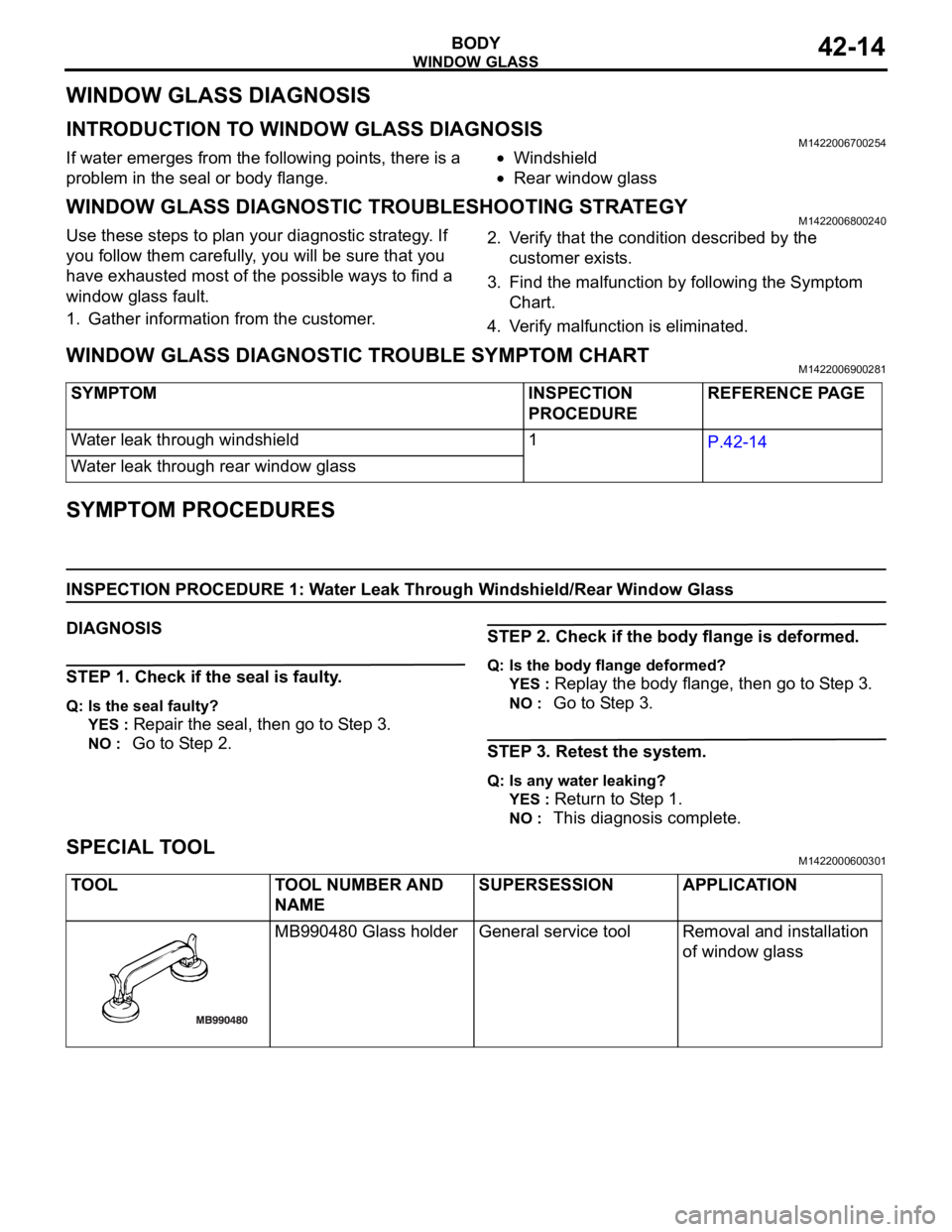
MB990480 Glass holder General service tool Removal and installation
of window glass