2005 MITSUBISHI 380 Brake pad
[x] Cancel search: Brake padPage 508 of 1500

HEADLINING
INTERIOR52A-19
HEADLINING
REMOVAL AND INSTALLATIONM1521001400360
Pre-removal and Post-installation Operation
Front Seat Assembly (Refer to P.52A-21.)
Removal and Installation of Rear Seat Cushion Assembly
and Rear Seatback Assembly (Refer to P.52A-55.)
Removal and Installation of Front Pillar Trim, Center Pillar
Trim Upper and Rear Pillar Trim (Refer to P.52A-11.)
REMOVAL STEPS
1. SUN VISOR
2. SUN VISOR HOLDER
3. OVERHEAD CONSOLE
ASSEMBLY
4. DOME LIGHT ASSEMBLY (REFER
TO GROUP 54A, DOME LIGHT
P.54A-163.)
5. ASSIST GRIP PLUG
6. ROOF INSIDE ASSIST GRIP
7. SUNROOF OPENING TRIM
INSTRUMENT PANEL SIDE
COVER (REFER TO P.52A-4.)
9. ROOF HARNESS CONNECTOR
FLOOR CONSOLE ASSEMBLY
(REFER TO P.52A-10.)
PARKING BRAKE LEVER
ASSEMBLY MOUNTING BOLT
(REFER TO GROUP 36, PARKING
BRAKE LEVER P.36-6.)
<>10. HEADLINING ASSEMBLY
11. OVERHEAD CONSOLE BRACKET
12. FRONT HEADLINING PAD REMOVAL STEPS (Continued)
Page 1158 of 1500
ON-VEHICLE SERVICE
CLUTCH21A-3
Do not push in the master cylinder pushrod at
this time, otherwise the clutch will not operate
properly.
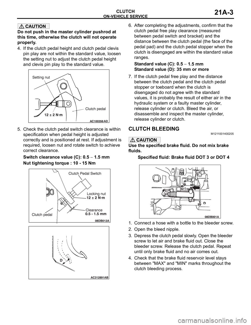
4. If the clutch pedal height and clutch pedal clevis
pin play are not within the standard value, loosen
the setting nut to adjust the clutch pedal height
and clevis pin play to the standard value.
5. Check the clutch pedal switch clearance is within
specification when pedal height is adjusted
correctly and is positioned at rest. If adjustment is
required, loosen nut and rotate switch to achieve
correct clearance.
Switch clearance value (C): 0.5
1.5 mm
Nut tightening torque : 10 - 15 Nm6. After completing the adjustments, confirm that the
clutch pedal free play clearance (measured
between pedal switch and bracket) and the
distance between the clutch pedal (the face of the
pedal pad) and the clutch pedal stopper when the
clutch is disengaged are within the standard value
ranges.
Standard value (C): 0.5
1.5 mm
Standard value (D): 35 mm or more
7. If the clutch pedal free play and the distance
between the clutch pedal and the clutch pedal
stopper or toeboard when the clutch is
disengaged do not agree with the standard
values, it is probably the result of either air in the
hydraulic system or a faulty master cylinder,
release cylinder or clutch. Bleed the air, or
disassemble and inspect the master cylinder,
release cylinder or clutch.
CLUTCH BLEEDINGM1211001400205
Use the specified brake fluid. Do not mix brake
fluids.
Specified fluid: Brake fluid DOT 3 or DOT 4
1. Connect a hose with a bottle to the bleeder screw.
2. Open the bleed nipple.
3. Depress the clutch pedal slowly. Open the bleeder
screw to let air and brake fluid out. Close the
bleeder screw. Release the clutch pedal. Repeat
until only brake fluid and no air comes out.
4. Check that the brake fluid reservoir level stays
between "MAX" and "MIN" marks throughout the
clutch bleeding process.
Page 1166 of 1500

35A-1
GROUP 35A
BASIC BRAKE
SYSTEM
CONTENTS
GENERAL DESCRIPTION. . . . . . . . .35A-2
BASIC BRAKE SYSTEM DIAGNOSIS35A-3
INTRODUCTION TO BASIC BRAKE
SYSTEM DIAGNOSIS . . . . . . . . . . . . . . . . 35A-3
BASIC BRAKE SYSTEM DIAGNOSTIC
TROUBLESHOOTING STRATEGY . . . . . . 35A-3
SYMPTOM CHART. . . . . . . . . . . . . . . . . . . 35A-3
SYMPTOM PROCEDURES . . . . . . . . . . . . 35A-3
SPECIAL TOOLS . . . . . . . . . . . . . . . .35A-12
ON-VEHICLE SERVICE . . . . . . . . . . .35A-13
BRAKE PEDAL CHECK AND
ADJUSTMENT . . . . . . . . . . . . . . . . . . . . . . 35A-13
BRAKE BOOSTER OPERATING TEST . . . 35A-14
CHECK VALVE OPERATION CHECK . . . . 35A-15
BLEEDING . . . . . . . . . . . . . . . . . . . . . . . . . 35A-16
BRAKE FLUID LEVEL SENSOR CHECK. . 35A-17
DISC BRAKE PAD CHECK AND
REPLACEMENT . . . . . . . . . . . . . . . . . . . . . 35A-17
DISC BRAKE ROTOR CHECK . . . . . . . . . . 35A-19
MASTER CYLINDER FUNCTION CHECK . 35A-23
BRAKE PEDAL. . . . . . . . . . . . . . . . . .35A-24
REMOVAL AND INSTALLATION . . . . . . . . 35A-24
INSPECTION. . . . . . . . . . . . . . . . . . . . . . . . 35A-25
MASTER CYLINDER ASSEMBLY
AND BRAKE BOOSTER . . . . . . . . . .35A-26
REMOVAL AND INSTALLATION . . . . . . . . 35A-26
MASTER CYLINDER . . . . . . . . . . . . . . . . . 35A-28
INSPECTION. . . . . . . . . . . . . . . . . . . . . . . . 35A-29
DISC BRAKE ASSEMBLY . . . . . . . . .35A-30
REMOVAL AND INSTALLATION . . . . . . . . 35A-30
INSPECTION. . . . . . . . . . . . . . . . . . . . . . . . 35A-32
DISASSEMBLY AND ASSEMBLY
DISASSEMBLY AND ASSEMBLY
INSPECTION. . . . . . . . . . . . . . . . . . . . . . . . 35A-38
SPECIFICATIONS . . . . . . . . . . . . . . .35A-40
FASTENER TIGHTENING
SPECIFICATIONS. . . . . . . . . . . . . . . . . . . . 35A-40
GENERAL SPECIFICATIONS . . . . . . . . . . 35A-40
SERVICE SPECIFICATIONS . . . . . . . . . . . 35A-41
LUBRICANTS . . . . . . . . . . . . . . . . . . . . . . . 35A-41
Page 1168 of 1500

BASIC BRAKE SYSTEM DIAGNOSIS
BASIC BRAKE SYSTEM35A-3
BASIC BRAKE SYSTEM DIAGNOSIS
INTRODUCTION TO BASIC BRAKE SYSTEM DIAGNOSISM1351009700319
Hydraulic brakes are composed of the brake pedal,
master cylinder, brake booster and disc brakes. Mal-
functions such as insufficient braking power or the
generation of noise may occur due to wear, damage
or incorrect adjustment of these components.
BASIC BRAKE SYSTEM DIAGNOSTIC TROUBLESHOOTING STRATEGYM1351009800316
Use these steps to plan your diagnostic strategy. If
you follow them carefully, you will be sure that you
have exhausted most of the possible ways to find a
basic brake system fault.
1. Gather information from the customer.2. Verify that the condition described by the
customer exists.
3. Find the malfunction by following the symptom
chart.
4. Verify malfunction is eliminated.
SYMPTOM CHARTM1351009900324
SYMPTOM PROCEDURES
INSPECTION PROCEDURE 1: Vehicle Pulls to One Side when Brakes are Applied
.DIAGNOSIS
STEP 1. Check for oil, water, etc., on the pad
contact surface of all brakes.
Q: Is oil, water, etc., on the pad contact surface?
YES :
Replace the part and determine the
source/cause of foreign material. Then go to
St e p 5.
NO : Go to Step 2. SYMPTOM INSPECTION
PROCEDUREREFERENCE
PA G E
Vehicle pulls to one side when brakes are applied 1
P.35A-3
Insufficient braking power 2
P.35A-4
Increased pedal stroke (Reduced pedal-to-floor board clearance)3
P.35A-5
Brake drag 4
P.35A-6
Scraping or grinding noise when brake are applied 5
P.35A-7
Squealing, groaning or chattering noise when brake are applied 6
P.35A-8
Squealing noise when brakes are not applied 7
P.35A-9
Groaning, clicking or rattling noise when brakes are not applied8
P.35A-11
Page 1170 of 1500
BASIC BRAKE SYSTEM DIAGNOSIS
BASIC BRAKE SYSTEM35A-5
STEP 4. Check for pinched or restricted brake
tube or hose.
Q: Is there a pinched or restricted brake tube or hose?
YES :
Replace that complete section of brake tube
or brake hose. Then go to Step 7.
NO : Go to Step 5.
STEP 5. Check for oil, water, etc., on the pad
contact surfaces of all brakes.
Q: Is oil, water, etc., on the pad contact surface?
YES :
Replace the part and determine the
source/cause of foreign material. Recheck
symptom. Then go to Step 7.
NO : The procedure is complete. If condition
persists for vehicles without ABS, go to Step
6.
STEP 7. Recheck symptom.
Q: Is the symptom eliminated?
YES :
The procedure is complete.
NO : Start over at step 1. If a new symptom
surfaces, refer to the appropriate symptom
chart.
INSPECTION PROCEDURE 3: Increased Pedal Stroke (Reduced Pedal-to-Floor Board Clearance)
.
DIAGNOSIS
STEP 1. Check for spongy (not firm) brakes.
(1) With engine not running, depress the brake pedal
rapidly several times to deplete booster vacuum
reserve.
(2) With the brake pedal fully released, depress the
brake pedal slowly until it stops.
(3) With a measuring device (ruler, etc.) next to the
brake pedal, depress the pedal firmly and
measure the distance the pedal traveled.
Q: Is the distance greater than 20 mm (0.8 inch)?
YES :
Bleed the brakes to remove air in the fluid
(Refer to P.35A-16). Then go to Step 7.
NO : Go to Step 2.
STEP 2. Check the pad for wear.
Refer to P.35A-17.
Q: Is the pad thickness outside of specifications?
YES :
Replace the part. Then go to Step 7.
NO : Go to Step 3.
STEP 3. Check the vacuum hose and check valve
for damage.
Refer to P.35A-15.
Q: Is there a damage?
YES :
Replace the part. Then go to Step 7.
NO : Go to Step 4.
STEP 4. Check the master cylinder function.
Refer to P.35A-23.
Q: Is there a fault?
YES :
Repair it. Then go to Step 7.
NO : Go to Step 5.
STEP 5. Check for brake fluid leaks.
Q: Is there a leak?
YES :
Check the connection for looseness,
corrosion, etc. Clean and repair as
necessary. If leaking in any tube or hose
section, replace the complete tube or hose.
Then go to Step 7 .
NO : Go to Step 6.
STEP 6. Check for excessive clearance between
the push rod and primary piston.
Refer to P.35A-26.
Q: Is the clearance outside of specifications?
YES :
Adjust the clearance. Then go to Step 7.
NO : Go to Step 7.
STEP 7. Recheck symptom.
Q: Is the symptom eliminated?
YES :
The procedure is complete.
NO : Start over at step 1. If a new symptom
surfaces, refer to the symptom chart.
Page 1173 of 1500
BASIC BRAKE SYSTEM DIAGNOSIS
BASIC BRAKE SYSTEM35A-8
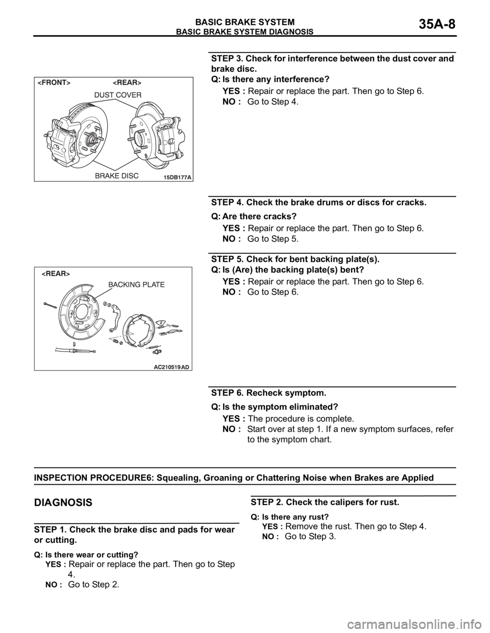
STEP 3. Check for interference between the dust cover and
brake disc.
Q: Is there any interference?
YES : Repair or replace the part. Then go to Step 6.
NO : Go to Step 4.
STEP 4. Check the brake drums or discs for cracks.
Q: Are there cracks?
YES : Repair or replace the part. Then go to Step 6.
NO : Go to Step 5.
STEP 5. Check for bent backing plate(s).
Q: Is (Are) the backing plate(s) bent?
YES : Repair or replace the part. Then go to Step 6.
NO : Go to Step 6.
STEP 6. Recheck symptom.
Q: Is the symptom eliminated?
YES : The procedure is complete.
NO : Start over at step 1. If a new symptom surfaces, refer
to the symptom chart.
INSPECTION PROCEDURE6: Squealing, Groaning or Chattering Noise when Brakes are Applied
.
DIAGNOSIS
STEP 1. Check the brake disc and pads for wear
or cutting.
Q: Is there wear or cutting?
YES :
Repair or replace the part. Then go to Step
4.
NO : Go to Step 2.
STEP 2. Check the calipers for rust.
Q: Is there any rust?
YES :
Remove the rust. Then go to Step 4.
NO : Go to Step 3.
Page 1174 of 1500
BASIC BRAKE SYSTEM DIAGNOSIS
BASIC BRAKE SYSTEM35A-9
STEP 3. Adjust the brake pedal or brake booster
pushrod.
Refer to P.35A-13 or P.35A-26.
Q: Are the brake pedal and the brake booster pushrod
adjusted correctly?
YES :
Go to Step 4.
NO : Adjust the brake pedal or the brake booster
pushrod. Then go to Step 4.
STEP 4. Recheck symptom.
Q: Is the symptom eliminated?
YES :
The procedure is complete.
NO : Start over at step 1. If a new symptom
surfaces, refer to the symptom chart.
INSPECTION PROCEDURE 7: Squealing Noise when Brakes are not Applied
DIAGNOSIS
.
STEP 1. Check whether the backing plate is bent or loose
and interfering with the drum.
Q: Is there a fault?
YES : Replace the part. Then go to Step 10.
NO : Go to Step 2.
STEP 2. Check whether the drum is damaged due to
interference with the backing plate or shoe.
Q: Is there any damage?
YES : Replace the part. Then go to Step 10.
NO : Go to Step 3.
STEP 3. Check the brake drum for wear and the shoe
spring for damage.
Q: Is there any wear or damage?
YES : Replace the part. Then go to Step 10.
NO : Go to Step 4.
STEP 4. Check the brake discs for rust.
Q: Are the brake discs rusted?
YES : Remove the rust by using sand paper. If still rusted,
turn the rotors with an on-the-car brake lathe. Then go
to Step 10.
NO : Go to Step 5.
STEP 5. Check the brake pads for correct installation.
Q: Are the pads installed incorrectly?
YES : Repair the pads. Then go to Step 10.
NO : Go to Step 6.
STEP 6. Check the calipers for correct installation.
Q: Are the calipers installed incorrectly?
YES : Repair the calipers. Then go to Step 10.
NO : Go to Step 7.
Page 1178 of 1500
ON-VEHICLE SERVICE
BASIC BRAKE SYSTEM35A-13
ON-VEHICLE SERVICE
BRAKE PEDAL CHECK AND ADJUSTMENTM1351000900446
BRAKE PEDAL HEIGHT
1. Turn up the carpet, etc. under the brake pedal.
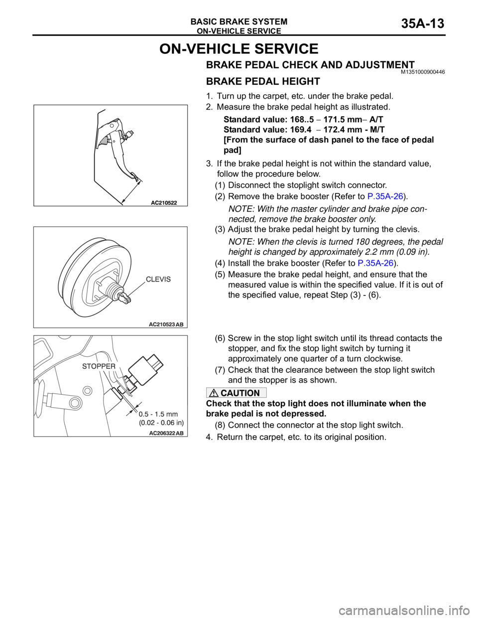
2. Measure the brake pedal height as illustrated.
Standard value: 168..5
171.5 mm A/T
Standard value: 169.4
172.4 mm - M/T
[From the surface of dash panel to the face of pedal
pad]
3. If the brake pedal height is not within the standard value,
follow the procedure below.
(1) Disconnect the stoplight switch connector.
(2) Remove the brake booster (Refer to P.35A-26).
NOTE: With the master cylinder and brake pipe con-
nected, remove the brake booster only.
(3) Adjust the brake pedal height by turning the clevis.
NOTE: When the clevis is turned 180 degrees, the pedal
height is changed by approximately 2.2 mm (0.09 in).
(4) Install the brake booster (Refer to P.35A-26).
(5) Measure the brake pedal height, and ensure that the
measured value is within the specified value. If it is out of
the specified value, repeat Step (3) - (6).
(6) Screw in the stop light switch until its thread contacts the
stopper, and fix the stop light switch by turning it
approximately one quarter of a turn clockwise.
(7) Check that the clearance between the stop light switch
and the stopper is as shown.
Check that the stop light does not illuminate when the
brake pedal is not depressed.
(8) Connect the connector at the stop light switch.
4. Return the carpet, etc. to its original position.