2005 MITSUBISHI 380 lock
[x] Cancel search: lockPage 1276 of 1500

MAINTENANCE SERVICE
GENERAL00-55
The SRS may not activate if any of the above compo-
nents are not installed properly, which could result in
serious injury or death to the vehicle's driver and
front passenger.
11.Check the steering wheel for excessive free play.
Replace any part if it fails visual inspection (Refer to
GROUP 52B, Air Bag Module and Clock Spring P.52B-237).
FRONT SEATBACK ASSEMBLY WITH
SIDE-AIRBAG MODULE
If any improper part is found during the following
inspection, replace the front seatback assembly
with a new one.
Dispose of the old one according to the specified
procedure (Refer to GROUP 52B, Air Bag Module
Disposal Procedures P.52B-254).
Never attempt to measure the circuit resistance of
the air bag module (squib) even if you are using
the specified tester. If the circuit resistance is mea-
sured with a tester, accidental air bag deployment
will result in serious personal injury.
1. Check the air bag module deployment section for dents or
deformation.
2. Check the connector for damage; Check the terminals for
deformation; and check the harness for binding.
Replace the front seat if it fails the visual checks above
(Refer to GROUP 52A, Front Seat P.52A-33).
SEAT BELT WITH PRE-TENSIONER
If the seat belt pre-tensioner is not installed
securely and correctly, the seat belt pre-tensioner
may not operate normally.
If a dent, crack, deformation or rust is detected,
replace with a new seat belt pre-tensioner.
1. Check the seat belt pre-tensioner for dents or deformation.
2. Check that the seat belt pre-tensioner is installed correctly to
the vehicle body.
Replace the seat belt pre-tensioner if it fails the visual
checks above (Refer to GROUP 52B, Seat Belt
Pre-tensioner P.52B-250).
Page 1283 of 1500
TRACTION CONTROL SYSTEM (TCL) DIAGNOSIS
TRACTION CONTROL SYSTEM (TCL)13C-4
To prevent damage to diagnostic tool MB991958, always
turn the ignition switch to the "LOCK" (OFF) position
before connecting or disconnecting diagnostic tool
MB991958.
1. Ensure that the ignition switch is at the "LOCK" (OFF)
position.
2. Start up the personal computer.
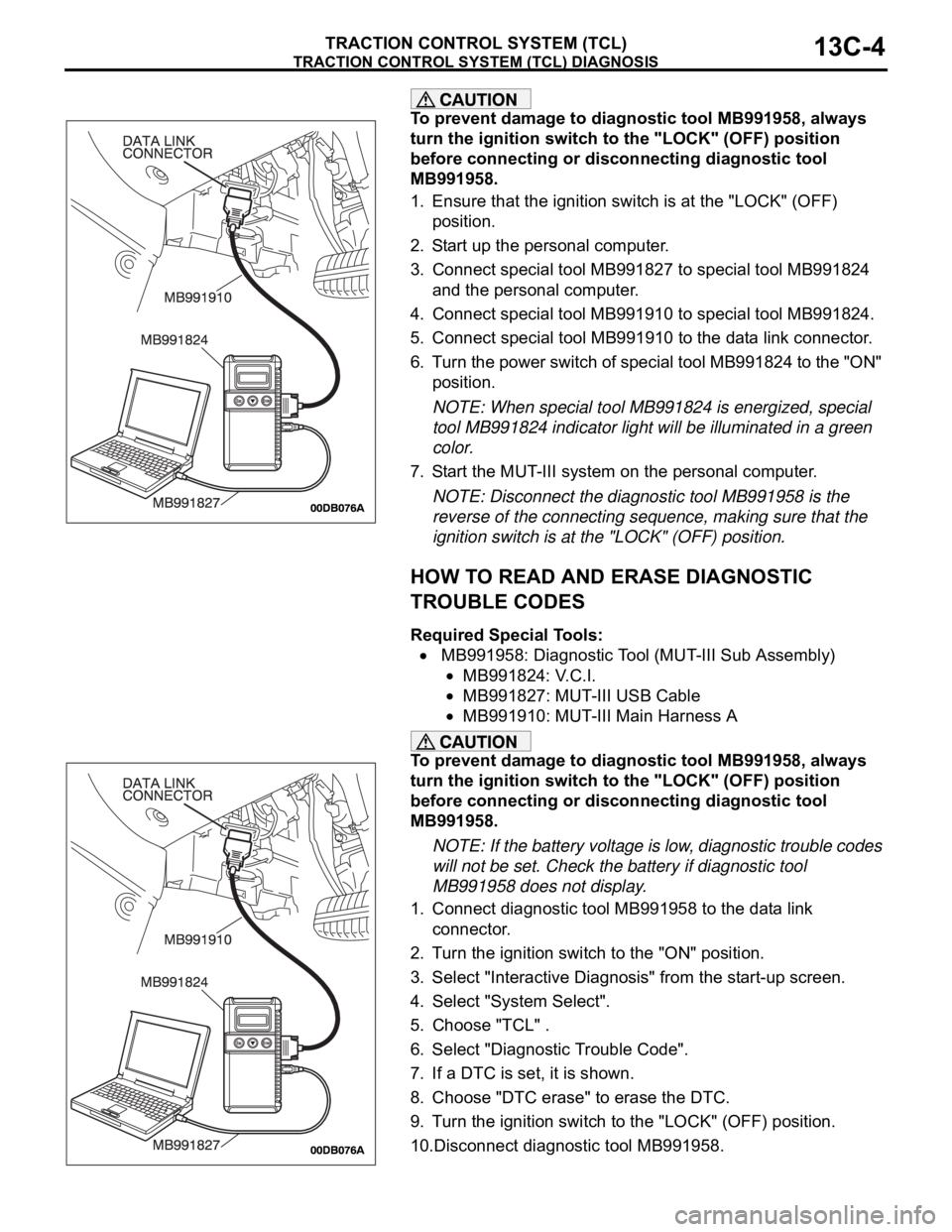
3. Connect special tool MB991827 to special tool MB991824
and the personal computer.
4. Connect special tool MB991910 to special tool MB991824.
5. Connect special tool MB991910 to the data link connector.
6. Turn the power switch of special tool MB991824 to the "ON"
position.
NOTE: When special tool MB991824 is energized, special
tool MB991824 indicator light will be illuminated in a green
color.
7. Start the MUT-III system on the personal computer.
NOTE: Disconnect the diagnostic tool MB991958 is the
reverse of the connecting sequence, making sure that the
ignition switch is at the "LOCK" (OFF) position.
HOW TO READ AND ERASE DIAGNOSTIC
TROUBLE CODES
Required Special Tools:
MB991958: Diagnostic Tool (MUT-III Sub Assembly)
MB991824: V.C.I.
MB991827: MUT-III USB Cable
MB991910: MUT-III Main Harness A
To prevent damage to diagnostic tool MB991958, always
turn the ignition switch to the "LOCK" (OFF) position
before connecting or disconnecting diagnostic tool
MB991958.
NOTE: If the battery voltage is low, diagnostic trouble codes
will not be set. Check the battery if diagnostic tool
MB991958 does not display.
1. Connect diagnostic tool MB991958 to the data link
connector.
2. Turn the ignition switch to the "ON" position.
3. Select "Interactive Diagnosis" from the start-up screen.
4. Select "System Select".
5. Choose "TCL" .
6. Select "Diagnostic Trouble Code".
7. If a DTC is set, it is shown.
8. Choose "DTC erase" to erase the DTC.
9. Turn the ignition switch to the "LOCK" (OFF) position.
10.Disconnect diagnostic tool MB991958.
Page 1284 of 1500
TRACTION CONTROL SYSTEM (TCL) DIAGNOSIS
TRACTION CONTROL SYSTEM (TCL)13C-5
HOW TO READ DATA LIST
Required Special Tools:
MB991958: Diagnostic Tool (MUT-III Sub Assembly)
MB991824: V.C.I.
MB991827: MUT-III USB Cable
MB991910: MUT-III Main Harness A
To prevent damage to diagnostic tool MB991958, always
turn the ignition switch to the "LOCK" (OFF) position
before connecting or disconnecting diagnostic tool
MB991958.
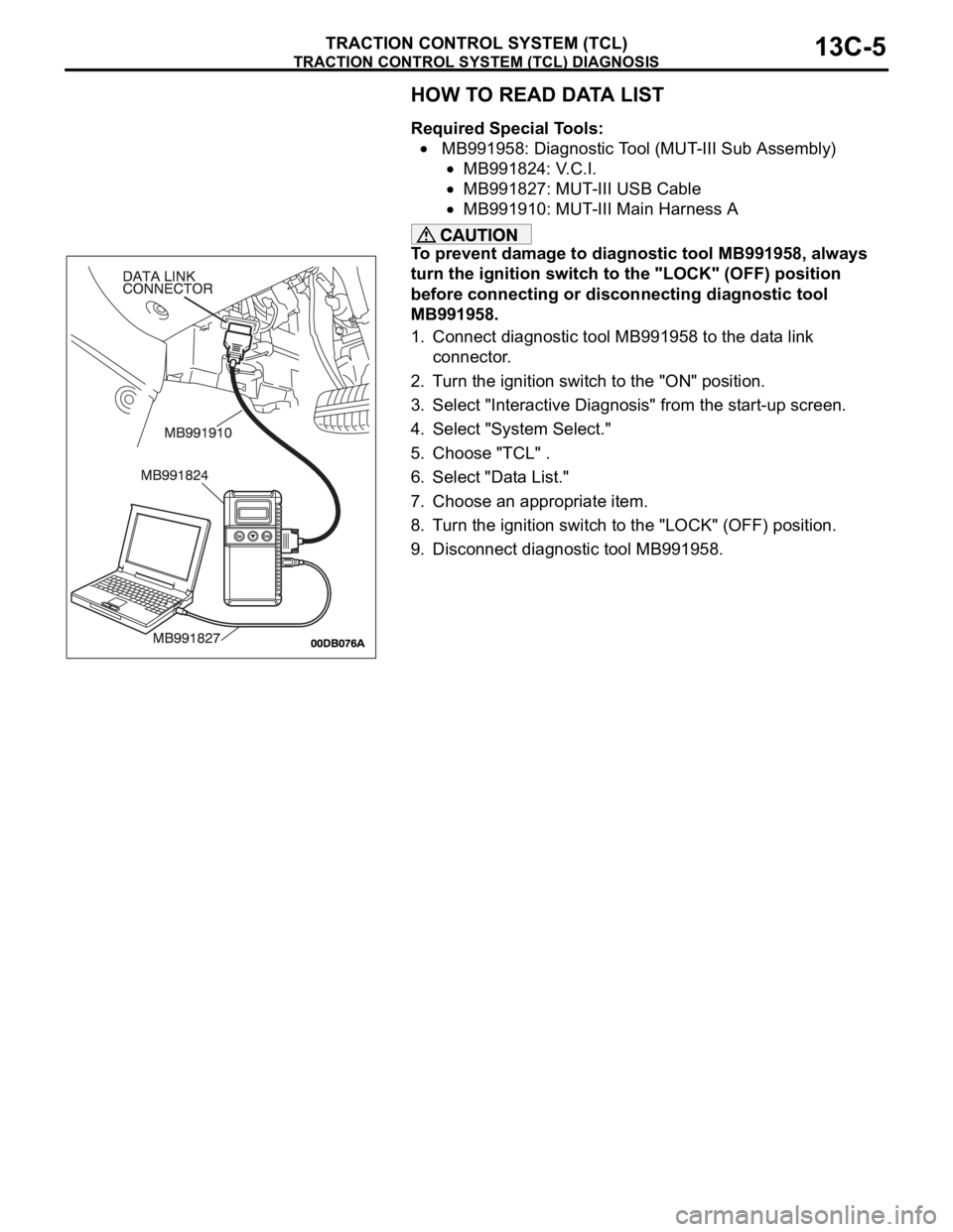
1. Connect diagnostic tool MB991958 to the data link
connector.
2. Turn the ignition switch to the "ON" position.
3. Select "Interactive Diagnosis" from the start-up screen.
4. Select "System Select."
5. Choose "TCL" .
6. Select "Data List."
7. Choose an appropriate item.
8. Turn the ignition switch to the "LOCK" (OFF) position.
9. Disconnect diagnostic tool MB991958.
Page 1285 of 1500
TRACTION CONTROL SYSTEM (TCL) DIAGNOSIS
TRACTION CONTROL SYSTEM (TCL)13C-6
HOW TO PERFORM ACTUATOR TEST
Required Special Tools:
MB991958: Diagnostic Tool (MUT-III Sub Assembly)
MB991824: V.C.I.
MB991827: MUT-III USB Cable
MB991910: MUT-III Main Harness A
To prevent damage to diagnostic tool MB991958, always
turn the ignition switch to the "LOCK" (OFF) position
before connecting or disconnecting diagnostic tool
MB991958.
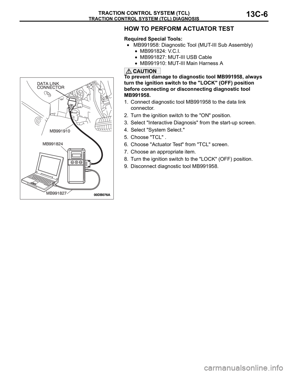
1. Connect diagnostic tool MB991958 to the data link
connector.
2. Turn the ignition switch to the "ON" position.
3. Select "Interactive Diagnosis" from the start-up screen.
4. Select "System Select."
5. Choose "TCL" .
6. Choose "Actuator Test" from "TCL" screen.
7. Choose an appropriate item.
8. Turn the ignition switch to the "LOCK" (OFF) position.
9. Disconnect diagnostic tool MB991958.
Page 1286 of 1500
TRACTION CONTROL SYSTEM (TCL) DIAGNOSIS
TRACTION CONTROL SYSTEM (TCL)13C-7
HOW TO DIAGNOSE THE CAN BUS LINE
Required Special Tools:
MB991958: Diagnostic Tool (MUT-III Sub Assembly)
MB991824: V.C.I.
MB991827: MUT-III USB Cable
MB991910: MUT-III Main Harness A
To prevent damage to diagnostic tool MB991958, always
turn the ignition switch to the "LOCK" (OFF) position
before connecting or disconnecting diagnostic tool
MB991958.
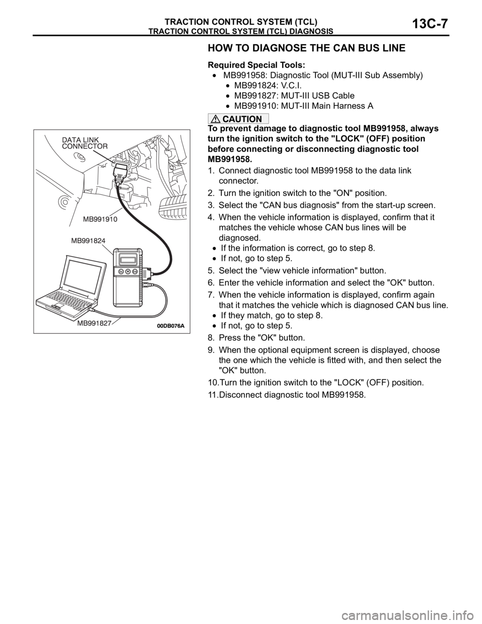
1. Connect diagnostic tool MB991958 to the data link
connector.
2. Turn the ignition switch to the "ON" position.
3. Select the "CAN bus diagnosis" from the start-up screen.
4. When the vehicle information is displayed, confirm that it
matches the vehicle whose CAN bus lines will be
diagnosed.
If the information is correct, go to step 8.
If not, go to step 5.
5. Select the "view vehicle information" button.
6. Enter the vehicle information and select the "OK" button.
7. When the vehicle information is displayed, confirm again
that it matches the vehicle which is diagnosed CAN bus line.
If they match, go to step 8.
If not, go to step 5.
8. Press the "OK" button.
9. When the optional equipment screen is displayed, choose
the one which the vehicle is fitted with, and then select the
"OK" button.
10.Turn the ignition switch to the "LOCK" (OFF) position.
11.Disconnect diagnostic tool MB991958.
Page 1290 of 1500
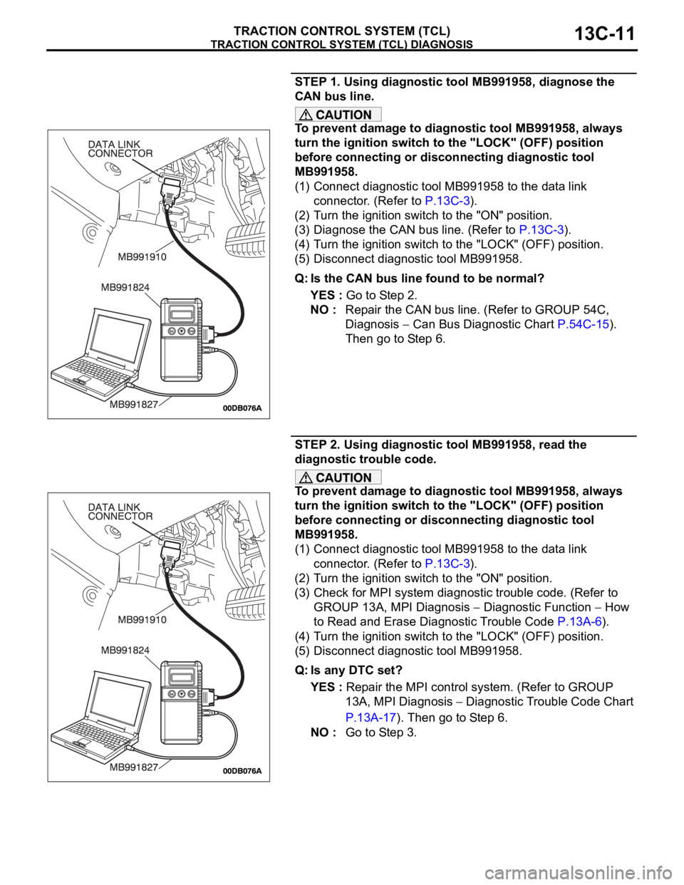
TRACTION CONTROL SYSTEM (TCL) DIAGNOSIS
TRACTION CONTROL SYSTEM (TCL)13C-11
STEP 1. Using diagnostic tool MB991958, diagnose the
CAN bus line.
To prevent damage to diagnostic tool MB991958, always
turn the ignition switch to the "LOCK" (OFF) position
before connecting or disconnecting diagnostic tool
MB991958.
(1) Connect diagnostic tool MB991958 to the data link
connector. (Refer to P.13C-3).
(2) Turn the ignition switch to the "ON" position.
(3) Diagnose the CAN bus line. (Refer to P.13C-3).
(4) Turn the ignition switch to the "LOCK" (OFF) position.
(5) Disconnect diagnostic tool MB991958.
Q: Is the CAN bus line found to be normal?
YES : Go to Step 2.
NO : Repair the CAN bus line. (Refer to GROUP 54C,
Diagnosis
Can Bus Diagnostic Chart P.54C-15).
Then go to Step 6.
STEP 2. Using diagnostic tool MB991958, read the
diagnostic trouble code.
To prevent damage to diagnostic tool MB991958, always
turn the ignition switch to the "LOCK" (OFF) position
before connecting or disconnecting diagnostic tool
MB991958.
(1) Connect diagnostic tool MB991958 to the data link
connector. (Refer to P.13C-3).
(2) Turn the ignition switch to the "ON" position.
(3) Check for MPI system diagnostic trouble code. (Refer to
GROUP 13A, MPI Diagnosis
Diagnostic Function How
to Read and Erase Diagnostic Trouble Code P.13A-6).
(4) Turn the ignition switch to the "LOCK" (OFF) position.
(5) Disconnect diagnostic tool MB991958.
Q: Is any DTC set?
YES : Repair the MPI control system. (Refer to GROUP
13A, MPI Diagnosis
Diagnostic Trouble Code Chart
P.13A-17). Then go to Step 6.
NO : Go to Step 3.
Page 1291 of 1500
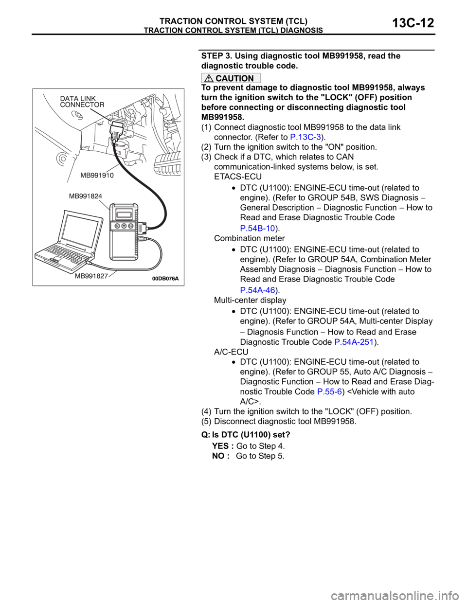
TRACTION CONTROL SYSTEM (TCL) DIAGNOSIS
TRACTION CONTROL SYSTEM (TCL)13C-12
STEP 3. Using diagnostic tool MB991958, read the
diagnostic trouble code.
To prevent damage to diagnostic tool MB991958, always
turn the ignition switch to the "LOCK" (OFF) position
before connecting or disconnecting diagnostic tool
MB991958.
(1) Connect diagnostic tool MB991958 to the data link
connector. (Refer to P.13C-3).
(2) Turn the ignition switch to the "ON" position.
(3) Check if a DTC, which relates to CAN
communication-linked systems below, is set.
ETACS-ECU
DTC (U1100): ENGINE-ECU time-out (related to
engine). (Refer to GROUP 54B, SWS Diagnosis
General Description
Diagnostic Function How to
Read and Erase Diagnostic Trouble Code
P.54B-10).
Combination meter
DTC (U1100): ENGINE-ECU time-out (related to
engine). (Refer to GROUP 54A, Combination Meter
Assembly Diagnosis
Diagnosis Function How to
Read and Erase Diagnostic Trouble Code
P.54A-46).
Multi-center display
DTC (U1100): ENGINE-ECU time-out (related to
engine). (Refer to GROUP 54A, Multi-center Display
Diagnosis Function How to Read and Erase
Diagnostic Trouble Code P.54A-251).
A/C-ECU
DTC (U1100): ENGINE-ECU time-out (related to
engine). (Refer to GROUP 55, Auto A/C Diagnosis
Diagnostic Function
How to Read and Erase Diag-
nostic Trouble Code P.55-6)
(4) Turn the ignition switch to the "LOCK" (OFF) position.
(5) Disconnect diagnostic tool MB991958.
Q: Is DTC (U1100) set?
YES : Go to Step 4.
NO : Go to Step 5.
Page 1292 of 1500
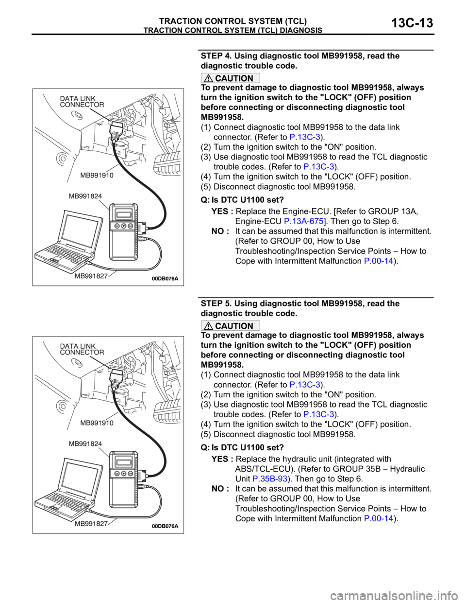
TRACTION CONTROL SYSTEM (TCL) DIAGNOSIS
TRACTION CONTROL SYSTEM (TCL)13C-13
STEP 4. Using diagnostic tool MB991958, read the
diagnostic trouble code.
To prevent damage to diagnostic tool MB991958, always
turn the ignition switch to the "LOCK" (OFF) position
before connecting or disconnecting diagnostic tool
MB991958.
(1) Connect diagnostic tool MB991958 to the data link
connector. (Refer to P.13C-3).
(2) Turn the ignition switch to the "ON" position.
(3) Use diagnostic tool MB991958 to read the TCL diagnostic
trouble codes. (Refer to P.13C-3).
(4) Turn the ignition switch to the "LOCK" (OFF) position.
(5) Disconnect diagnostic tool MB991958.
Q: Is DTC U1100 set?
YES : Replace the Engine-ECU. [Refer to GROUP 13A,
Engine-ECU P.13A-675]. Then go to Step 6.
NO : It can be assumed that this malfunction is intermittent.
(Refer to GROUP 00, How to Use
Troubleshooting/Inspection Service Points
How to
Cope with Intermittent Malfunction P.00-14).
STEP 5. Using diagnostic tool MB991958, read the
diagnostic trouble code.
To prevent damage to diagnostic tool MB991958, always
turn the ignition switch to the "LOCK" (OFF) position
before connecting or disconnecting diagnostic tool
MB991958.
(1) Connect diagnostic tool MB991958 to the data link
connector. (Refer to P.13C-3).
(2) Turn the ignition switch to the "ON" position.
(3) Use diagnostic tool MB991958 to read the TCL diagnostic
trouble codes. (Refer to P.13C-3).
(4) Turn the ignition switch to the "LOCK" (OFF) position.
(5) Disconnect diagnostic tool MB991958.
Q: Is DTC U1100 set?
YES : Replace the hydraulic unit (integrated with
ABS/TCL-ECU). (Refer to GROUP 35B
Hydraulic
Unit P.35B-93). Then go to Step 6.
NO : It can be assumed that this malfunction is intermittent.
(Refer to GROUP 00, How to Use
Troubleshooting/Inspection Service Points
How to
Cope with Intermittent Malfunction P.00-14).