Page 1178 of 1500

ON-VEHICLE SERVICE
BASIC BRAKE SYSTEM35A-13
ON-VEHICLE SERVICE
BRAKE PEDAL CHECK AND ADJUSTMENTM1351000900446
BRAKE PEDAL HEIGHT
1. Turn up the carpet, etc. under the brake pedal.
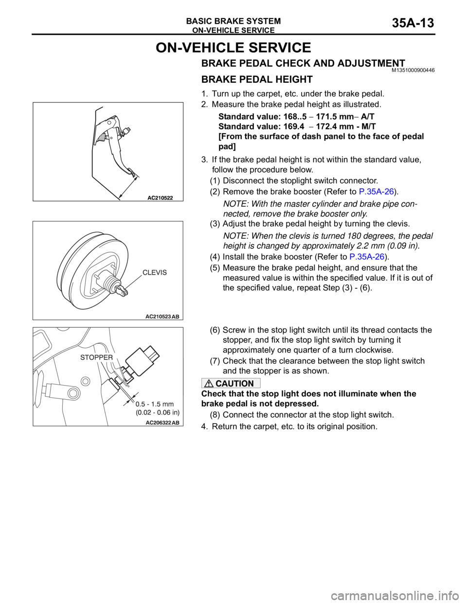
2. Measure the brake pedal height as illustrated.
Standard value: 168..5
171.5 mm A/T
Standard value: 169.4
172.4 mm - M/T
[From the surface of dash panel to the face of pedal
pad]
3. If the brake pedal height is not within the standard value,
follow the procedure below.
(1) Disconnect the stoplight switch connector.
(2) Remove the brake booster (Refer to P.35A-26).
NOTE: With the master cylinder and brake pipe con-
nected, remove the brake booster only.
(3) Adjust the brake pedal height by turning the clevis.
NOTE: When the clevis is turned 180 degrees, the pedal
height is changed by approximately 2.2 mm (0.09 in).
(4) Install the brake booster (Refer to P.35A-26).
(5) Measure the brake pedal height, and ensure that the
measured value is within the specified value. If it is out of
the specified value, repeat Step (3) - (6).
(6) Screw in the stop light switch until its thread contacts the
stopper, and fix the stop light switch by turning it
approximately one quarter of a turn clockwise.
(7) Check that the clearance between the stop light switch
and the stopper is as shown.
Check that the stop light does not illuminate when the
brake pedal is not depressed.
(8) Connect the connector at the stop light switch.
4. Return the carpet, etc. to its original position.
Page 1179 of 1500

ON-VEHICLE SERVICE
BASIC BRAKE SYSTEM35A-14
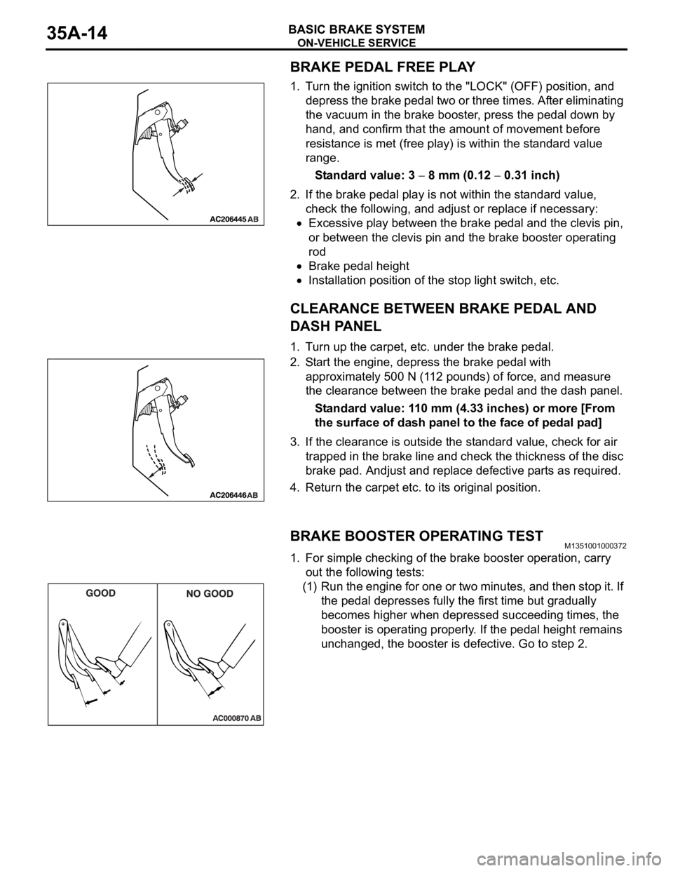
BRAKE PEDAL FREE PLAY
1. Turn the ignition switch to the "LOCK" (OFF) position, and
depress the brake pedal two or three times. After eliminating
the vacuum in the brake booster, press the pedal down by
hand, and confirm that the amount of movement before
resistance is met (free play) is within the standard value
range.
Standard value: 3
8 mm (0.12 0.31 inch)
2. If the brake pedal play is not within the standard value,
check the following, and adjust or replace if necessary:
Excessive play between the brake pedal and the clevis pin,
or between the clevis pin and the brake booster operating
rod
Brake pedal height
Installation position of the stop light switch, etc.
CLEARANCE BETWEEN BRAKE PEDAL AND
DASH PANEL
1. Turn up the carpet, etc. under the brake pedal.
2. Start the engine, depress the brake pedal with
approximately 500 N (112 pounds) of force, and measure
the clearance between the brake pedal and the dash panel.
Standard value: 110 mm (4.33 inches) or more [From
the surface of dash panel to the face of pedal pad]
3. If the clearance is outside the standard value, check for air
trapped in the brake line and check the thickness of the disc
brake pad. Andjust and replace defective parts as required.
4. Return the carpet etc. to its original position.
BRAKE BOOSTER OPERATING TESTM1351001000372
1. For simple checking of the brake booster operation, carry
out the following tests:
(1) Run the engine for one or two minutes, and then stop it. If
the pedal depresses fully the first time but gradually
becomes higher when depressed succeeding times, the
booster is operating properly. If the pedal height remains
unchanged, the booster is defective. Go to step 2.
Page 1183 of 1500
ON-VEHICLE SERVICE
BASIC BRAKE SYSTEM35A-18
Do not wipe off the special grease that is on the lock pin.
Do not contaminate the lock pin.
2. Remove the lock pin bolt . Pivot the caliper assembly
upward and secure. Hold lock pin with spanner while
loosening bolt(Rear).
Page 1184 of 1500
ON-VEHICLE SERVICE
BASIC BRAKE SYSTEM35A-19
3. Remove the following parts from the caliper support.
(1) Pad assembly
(2) Clip
4. In order to measure the brake drag force after pad
installation, measure the rotary-sliding resistance of the hub
with the pads removed (Refer to P.35A-30).
5. Install the pads and caliper assembly, and then check the
brake drag force (Refer to P.35A-30).
6. Tighten lock pin bolt. Ensure lock pin is held with spanner
while tightening lock pin bolt(Rear) to specified torque.
DISC BRAKE ROTOR CHECKM1351002900334
Disc brakes must be kept within the allowable
service values in order to maintain normal brake
operation.
Before turning the brake disc, the following condi-
tions should be checked.
Page 1189 of 1500
BRAKE PEDAL
BASIC BRAKE SYSTEM35A-24
BRAKE PEDAL
REMOVAL AND INSTALLATIONM1351003400406
Post-installation Operation
Brake Pedal Adjustment (Refer to P.35A-13).
REMOVAL STEPS
1. BRAKE BOOSTER PIN
2. BRAKE BOOSTER PIN ASSEMBLY
3. SHIFT LOCK CABLE CONNECTION
4. STOPLIGHT SWITCH CONNECTOR
5. STOPLIGHT SWITCH
6. BRAKE PEDAL CLIPWIRING HARNESSES CLAMPED
ON BRAKE PEDAL ASSEMBLY
7. BRAKE PEDAL BOLT
8. BRAKE BOOSTER NUT
9. BRAKE PEDAL ASSEMBLY
10. BRAKE PEDAL PAD
11. BRAKE PEDAL STOPPERREMOVAL STEPS (Continued)
Page 1196 of 1500

DISC BRAKE ASSEMBLY
BASIC BRAKE SYSTEM35A-31
INSTALLATION SERVICE POINT
.
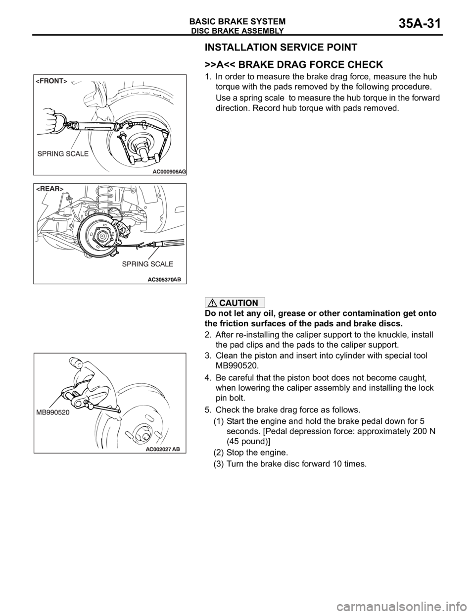
>>A<< BRAKE DRAG FORCE CHECK
1. In order to measure the brake drag force, measure the hub
torque with the pads removed by the following procedure.
Use a spring scale to measure the hub torque in the forward
direction. Record hub torque with pads removed.
Do not let any oil, grease or other contamination get onto
the friction surfaces of the pads and brake discs.
2. After re-installing the caliper support to the knuckle, install
the pad clips and the pads to the caliper support.
3. Clean the piston and insert into cylinder with special tool
MB990520.
4. Be careful that the piston boot does not become caught,
when lowering the caliper assembly and installing the lock
pin bolt.
5. Check the brake drag force as follows.
(1) Start the engine and hold the brake pedal down for 5
seconds. [Pedal depression force: approximately 200 N
(45 pound)]
(2) Stop the engine.
(3) Turn the brake disc forward 10 times.
Page 1197 of 1500
DISC BRAKE ASSEMBLY
BASIC BRAKE SYSTEM35A-32
(4) Use a spring scale to measure the hub torque with pads
installed in the same direction as earlier.
(5) Calculate the drag force of the disc brake [difference
between hub torque with pads installed and hub torque
with pads removed].
Standard value:
3.8L engine> 64 N (14 pounds) or less
54 N (12 pounds) or less
6. If the brake drag force exceeds the standard value,
disassemble and clean the piston. Check for corrosion or
worn piston seal, and check the sliding condition of the lock
pin and guide pin.
INSPECTIONM1351008100046.
BRAKE DISC CHECK
Disc wear (Refer to P.35A-19).
Disc run-out (Refer to P.35A-19).
Page 1203 of 1500