Page 1101 of 1500

DOOR
BODY42-34
CIRCUIT BREAKER (INCORPORATED IN THE
POWER WINDOW MOTOR) INSPECTION
M1429001000284
1. Pull the power window switch to the UP position to fully
close the door window glass, and keep pulling the switch for
an additional ten seconds.
2. Release the power window switch from the UP position and
immediately press it to the DOWN position. The condition of
the circuit breaker is good if the door window glass starts to
move downwards within about 60 seconds.
POWER WINDOW CHECKM1429004400214
1. Operate the power window switch of each door to verify that
the power windows operate properly. If they don't, then
troubleshoot as described in GROUP 54B, SWS Diagnosis
P.54B-57.
2. Turn ON the power window lock switch of the power window
main switch. Then operate the passenger's door and rear
door power window sub-switches to ensure that they do not
operate. If they do, replace the power window main switch
(Refer to P.42-39).
CENTRAL DOOR LOCKING SYSTEM
INSPECTION
M1427001100144
Check the following. Troubleshoot if operations malfunction
(Refer to GROUP 54B, SWS Diagnosis P.54B-57).
Insert the key into the driver's key cylinder and turn once to
the unlock side to unlock the driver's door and fuel lid door.
Turn the key once again to the unlock side to unlock all
doors and fuel lid door.
All doors and fuel lid door can be locked using the door lock
switch built into the front power window (main or sub )
switch.
Page 1103 of 1500
DOOR
BODY42-36
DOOR INSIDE HANDLE LOCK KNOB STROKE
CHECK
1. Remove the door trim assembly (Refer to GROUP 52A,
Door Trim P.52A-14).
2. Check that the door inside handle lock knob stroke is within
the standard value.
Standard value (B): 21.6 mm (0.850 inch)
3. If not within the standard value, adjust the inside handle lock
knob stroke with the outer cable end connecting the inside
handle lock knob and inside lock cable.
Page 1111 of 1500
DOOR
BODY42-44
NOTE: *: Set the window lock switch to UNLOCK position.
.Sub switch
Sub switch REAR (RH) UP 4
10, 6 2* Less than 2 ohms
OFF 4
6, 4 2*, 6 2* Less than 2 ohms
DOWN 6
10, 4 2* Less than 2 ohms
REAR (RH) UP 1
10, 3 2* Less than 2 ohms
OFF 3
1, 3 2*, 2* 1 Less than 2 ohms
DOWN 3
10, 2* 1 Less than 2 ohms
SWITCH POSITION TESTER
CONNECTIONSPECIFIED
CONDITION
UP 4
5, 6 7 Less than 2 ohms
OFF 4
5, 7 8 Less than 2 ohms
DOWN 4
6, 7 8 Less than 2 ohms
SWITCH POSITION TESTER
CONNECTIONSPECIFIED
CONDITION
UP 4
5, 6 7 Less than 2 ohms
OFF 4
5, 7 8 Less than 2 ohms
DOWN 4
6, 7 8 Less than 2 ohms SWITCH POSITION TESTER
CONNECTIONSPECIFIED
CONDITION
Page 1113 of 1500
DOOR
BODY42-46
DOOR HANDLE AND LATCH
REMOVAL AND INSTALLATIONM1423004600340
Pre-removal Operation
Door Trim Assembly Removal (Refer to GROUP 52A
Door Trim P.52A-14).Post-installation OperationDoor Inside Handle Play Check (Refer to P.42-35).
Door Outside Handle Play Check (Refer to P.42-35).
Door Trim Assembly Installation (Refer to GROUP 52A,
Door Trim P.52A-14).
DOOR HANDLE AND DOOR LATCH
ASSEMBLY REMOVAL STEPS
1. DOOR INSIDE HANDLE
WATERPROOF FILM (REFER TO
P.42-52).
>>B<<2. LOWER SASH
3. DOOR LATCH ASSEMBLY4. INSIDE LOCK CABLE
5. INSIDE HANDLE CABLE
6. DOOR OUTSIDE HANDLE
MOUNTING BOLT DOOR HANDLE AND DOOR LATCH
ASSEMBLY REMOVAL STEPS
Page 1114 of 1500
Page 1115 of 1500
Page 1116 of 1500

DOOR
BODY42-49
INSPECTIONM1423004700411
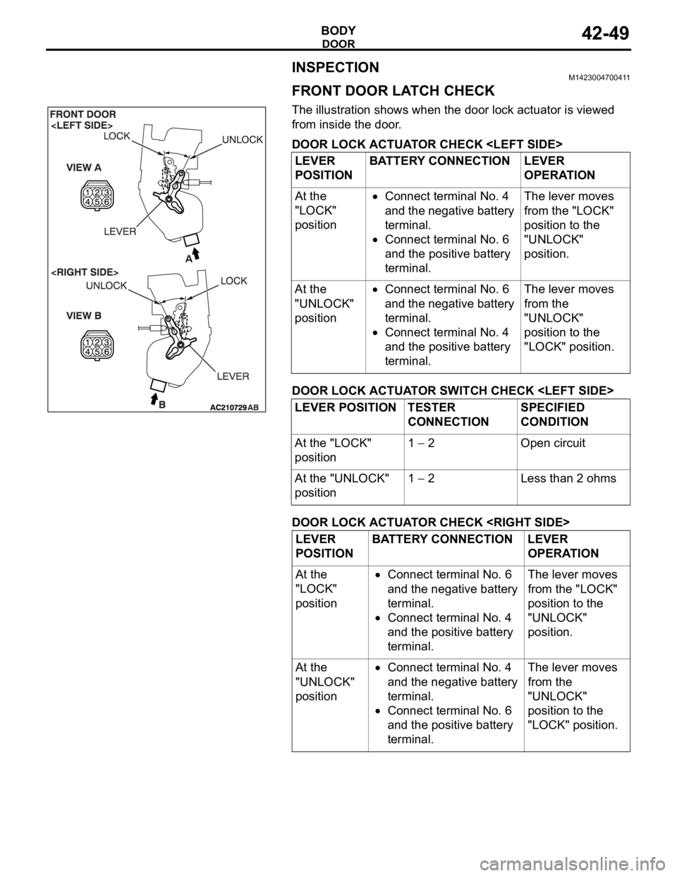
FRONT DOOR LATCH CHECK
The illustration shows when the door lock actuator is viewed
from inside the door.
DOOR LOCK ACTUATOR CHECK
DOOR LOCK ACTUATOR SWITCH CHECK
DOOR LOCK ACTUATOR CHECK LEVER
POSITIONBATTERY CONNECTION LEVER
OPERATION
At the
"LOCK"
position
Connect terminal No. 4
and the negative battery
terminal.
Connect terminal No. 6
and the positive battery
terminal.The lever moves
from the "LOCK"
position to the
"UNLOCK"
position.
At the
"UNLOCK"
position
Connect terminal No. 6
and the negative battery
terminal.
Connect terminal No. 4
and the positive battery
terminal.The lever moves
from the
"UNLOCK"
position to the
"LOCK" position.
LEVER POSITION TESTER
CONNECTIONSPECIFIED
CONDITION
At the "LOCK"
position1
2 Open circuit
At the "UNLOCK"
position1
2 Less than 2 ohms
LEVER
POSITIONBATTERY CONNECTION LEVER
OPERATION
At the
"LOCK"
position
Connect terminal No. 6
and the negative battery
terminal.
Connect terminal No. 4
and the positive battery
terminal.The lever moves
from the "LOCK"
position to the
"UNLOCK"
position.
At the
"UNLOCK"
position
Connect terminal No. 4
and the negative battery
terminal.
Connect terminal No. 6
and the positive battery
terminal.The lever moves
from the
"UNLOCK"
position to the
"LOCK" position.
Page 1117 of 1500

DOOR
BODY42-50
DOOR LOCK ACTUATOR SWITCH CHECK
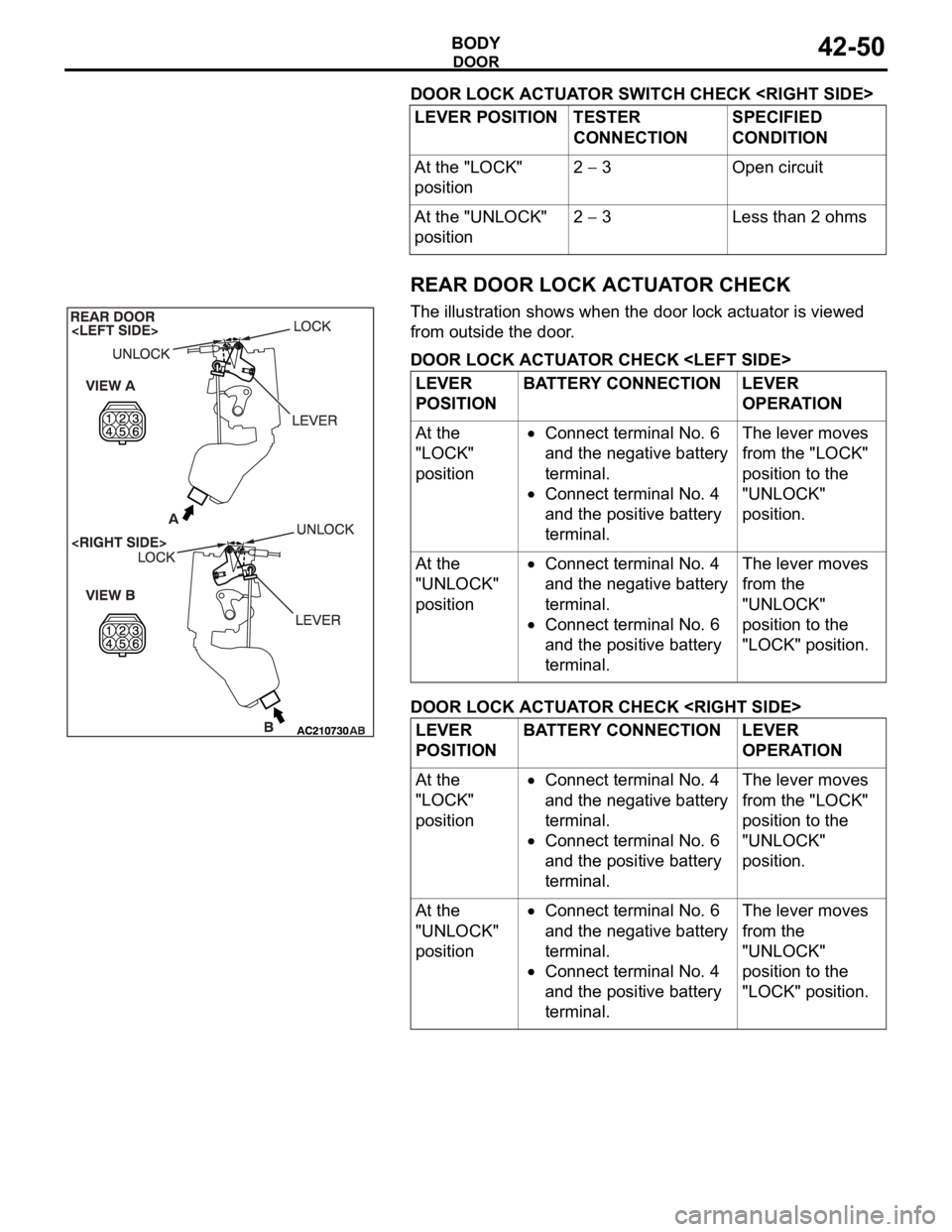
REAR DOOR LOCK ACTUATOR CHECK
The illustration shows when the door lock actuator is viewed
from outside the door.
DOOR LOCK ACTUATOR CHECK
DOOR LOCK ACTUATOR CHECK LEVER POSITION TESTER
CONNECTIONSPECIFIED
CONDITION
At the "LOCK"
position2
3 Open circuit
At the "UNLOCK"
position2
3 Less than 2 ohms
LEVER
POSITIONBATTERY CONNECTION LEVER
OPERATION
At the
"LOCK"
position
Connect terminal No. 6
and the negative battery
terminal.
Connect terminal No. 4
and the positive battery
terminal.The lever moves
from the "LOCK"
position to the
"UNLOCK"
position.
At the
"UNLOCK"
position
Connect terminal No. 4
and the negative battery
terminal.
Connect terminal No. 6
and the positive battery
terminal.The lever moves
from the
"UNLOCK"
position to the
"LOCK" position.
LEVER
POSITIONBATTERY CONNECTION LEVER
OPERATION
At the
"LOCK"
position
Connect terminal No. 4
and the negative battery
terminal.
Connect terminal No. 6
and the positive battery
terminal.The lever moves
from the "LOCK"
position to the
"UNLOCK"
position.
At the
"UNLOCK"
position
Connect terminal No. 6
and the negative battery
terminal.
Connect terminal No. 4
and the positive battery
terminal.The lever moves
from the
"UNLOCK"
position to the
"LOCK" position.