Page 1253 of 1500

TIGHTENING TORQUE
GENERAL00-32
TIGHTENING TORQUEM1001001100555
Each torque value in the table is a standard value for
tightening under the following conditions.
1. Bolts, nuts and washers are all made of steel and
plated with zinc.
2. The threads and bearing surface of bolts and
nuts are all in dry condition.
The values in the table are not applicable:1. If toothed washers are inserted.
2. If plastic parts are fastened.
3. If bolts are tightened to plastic or die-cast
inserted nuts.
4. If self-tapping screws or self-locking nuts are
used.
STANDARD BOLT AND NUT TIGHTENING TORQUE Engine Model No. 6G75
Total displacement 3,828cc
Automatic
TransaxleModel No. F5A5A-4-C2Z
Type 5-speed automatic
Manual
Trans.Model No. F 5M51
Type 5-speed manual
Fuel
systemFuel supply system Electronic controlled multipoint fuel injection (MPI) ITEM 380, 380LS, 380LX 380VRX, 380GT
THREAD SIZE STANDARD TIGHTENING TORQUE
NOMINAL BOLT
DIAMETER (mm)PITCH
(mm)HEAD MARK "4" HEAD MARK "7" HEAD MARK "8"
M5 0.8 2.5
0.5 Nm (23 4
in-lb)5.0 1.0 Nm (44 9
in-lb)6.0 1.0 Nm (53 9
in-lb)
M6 1.0 5.0
1.0 Nm (44 9
in-lb)8.5 1.5 Nm (76 13
in-lb)10 2 Nm (89 17
in-lb)
M8 1.25 11
2 Nm (98 17
in-lb)20 4 Nm (15 3 ft-lb) 24 4 Nm (18 3 ft-lb)
M10 1.25 23
4 Nm (17 3 ft-lb) 42 8 Nm (31 6 ft-lb) 53 7 Nm (39 5 ft-lb)
M12 1.25 42
8 Nm (31 6 ft-lb) 80 10 Nm (59 7
ft-lb)93 12 Nm (68 9
ft-lb)
M14 1.5 70
10 Nm (52 7
ft-lb)130 20 Nm (96 15
ft-lb)150 20 Nm ( 111 14
ft-lb)
M16 1.5 105
15 Nm (78 11
ft-lb)195 25 Nm (144 18
ft-lb)230 30 Nm (170 22
ft-lb)
M18 1.5 150
20 Nm ( 111 14
ft-lb)290 40 Nm (214 29
ft-lb)335 45 Nm (247 33
ft-lb)
Page 1260 of 1500
MAINTENANCE SERVICE
GENERAL00-39
7. DRIVE BELTS (FOR ALTERNATOR, POWER
STEERING PUMP AND AIR CONDITIONING)
(CHECK)
M1001008700031
ALTERNATOR DRIVE BELT TENSION CHECK
<3.8L ENGINE>
.
WHEN USING DIAGNOSTIC TOOL (MUT-III)
Required Special Tools:
MB991668: Belt Tension Meter Set
Diagnostic Tool (MUT-III)
MB991824: Vehicle Communication Interface (V.C.I.)
MB991910: MUT-III Main Harness A (BLUE)
To prevent damage to DIAGNOSTIC TOOL (MUT-III), always
turn the ignition switch to the "LOCK" (OFF) position
before connecting or disconnecting.
1. Connect Belt Tension Meter Set (MB991668) to V.C.I
(MB991824).
2. Connect MUT-III Main Harness A (BLUE) (MB991910) to
V.C.I (MB991824).
3. Connect MUT-III Main Harness A (BLUE) (MB991910) to the
data link connector.
4. Turn the ignition switch to the "ON" position and select "Belt
Tension" from the menu V.C.I (MB991824) screen.
Page 1264 of 1500

MAINTENANCE SERVICE
GENERAL00-43
WHEN USING A TENSION GAUGE
Use a belt tension gauge to check that the belt tension is within
the standard value.
Standard value:
.
BELT DEFLECTION CHECK
Apply approximately 98 N (22 lb) of force to the middle of the
drive belt between the pulleys (at the place indicated by the
arrow) and check that the amount of deflection is within the
standard value.
Standard value:
.if the tension or deflection is outside the standard value, adjust
by the following procedure.
1. Loosen the tensioner pulley lock nut.
2. Adjust the belt tension to the standard value by turning the
adjusting bolt. The tension will increase when turning the
adjusting bolt clockwise, and decrease when turning
counterclockwise.
3. Tighten the lock nut to the specified torque.
Tightening torque: 49
9 Nm (36 7 ft-lb)
4. Tighten the adjusting bolt.
Tightening torque: 5.0
1.0 Nm (44 9 in-lb)
Check after turning the crankshaft one or more rotations
clockwise.
5. Check the belt deflection amount and tension, and readjust
if necessary.
ITEM WHEN
CHECKEDDURING
ADJUSTMENTDURING
REPLACEMENT
Te n s i o n N
(lb)294 490
(66
110)343
441
(77
99)490
686
(110
154)
ITEM WHEN
CHECKEDDURING
ADJUSTMENTDURING
REPLACEMENT
Deflection
(Reference
value) mm
(in)12.3 16.2
(0.48
0.64)13.2
15.1
(0.52
0.59)9.6
12.3
(0.38
0.48)
Page 1268 of 1500

MAINTENANCE SERVICE
GENERAL00-47
6. Securely insert the dipstick.
NOTE: The transmission fluid should always be replaced
under the following conditions:
.
When troubleshooting the transaxle.
When overhauling the transaxle.
When the transmission fluid is noticeably dirty or burnt
(driving under severe conditions).
TRANSMISSION FLUID CHANGE
Refer to GROUP 23A, Automatic Transmission - On-vehicle
Service P.23A-296.
12. ENGINE COOLANT (CHANGE)M1001003100357
Check the cooling system parts such as the radiator, heater
and oil cooler hoses, thermostat and their connections for leak-
age and damage.
.
CHANGING COOLANT
1. Set the temperature control knob to the "HOT" position.
2. Run the engine until the engine coolant warms, and then
stop the engine.
When removing the radiator cap, use care to avoid
contact with hot coolant or steam. Place a shop towel
over the cap and turn the cap counterclockwise a lit-
tle to let the pressure escape through the vinyl tube.
After relieving the steam pressure, remove the cap by
slowly turning it counterclockwise.
3. Drain the water from the radiator, heater core and engine
after unplugging the radiator drain plug and removing the
radiator cap.
Page 1269 of 1500

MAINTENANCE SERVICE
GENERAL00-48
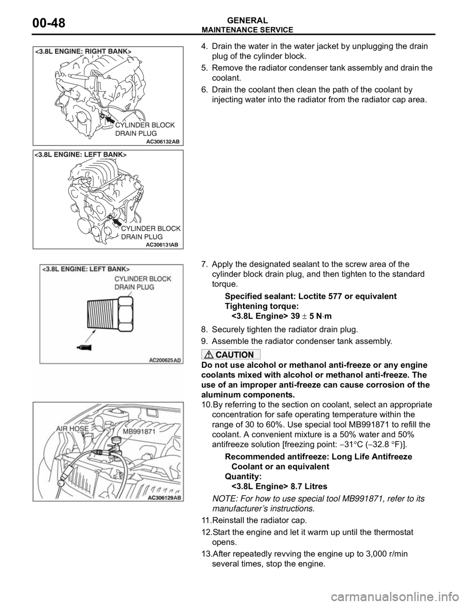
4. Drain the water in the water jacket by unplugging the drain
plug of the cylinder block.
5. Remove the radiator condenser tank assembly and drain the
coolant.
6. Drain the coolant then clean the path of the coolant by
injecting water into the radiator from the radiator cap area.
7. Apply the designated sealant to the screw area of the
cylinder block drain plug, and then tighten to the standard
torque.
Specified sealant: Loctite 577 or equivalent
Tightening torque:
<3.8L Engine> 39
5 Nm
8. Securely tighten the radiator drain plug.
9. Assemble the radiator condenser tank assembly.
Do not use alcohol or methanol anti-freeze or any engine
coolants mixed with alcohol or methanol anti-freeze. The
use of an improper anti-freeze can cause corrosion of the
aluminum components.
10.By referring to the section on coolant, select an appropriate
concentration for safe operating temperature within the
range of 30 to 60%. Use special tool MB991871 to refill the
coolant. A convenient mixture is a 50% water and 50%
antifreeze solution [freezing point:
31C (32.8 F)].
Recommended antifreeze: Long Life Antifreeze
Coolant or an equivalent
Quantity:
<3.8L Engine> 8.7 Litres
NOTE: For how to use special tool MB991871, refer to its
manufacturer’s instructions.
11.Reinstall the radiator cap.
12.Start the engine and let it warm up until the thermostat
opens.
13.After repeatedly revving the engine up to 3,000 r/min
several times, stop the engine.
Page 1272 of 1500

MAINTENANCE SERVICE
GENERAL00-51
18. SUSPENSION SYSTEM (INSPECT FOR
LOOSENESS AND DAMAGE)
M1001009600048
Visually inspect the front/rear suspension components for dete-
rioration and damage. Re-tighten the front/rear suspension
components retaining bolts to specified torque.
19. SRS AIR BAG (INSPECT FOR SRS SYSTEM)M1001003700326
The entire SRS including air bag and pre-tensioner seat belt
must be inspected by an authorized MITSUBISHI MOTORS
dealer 10 years.
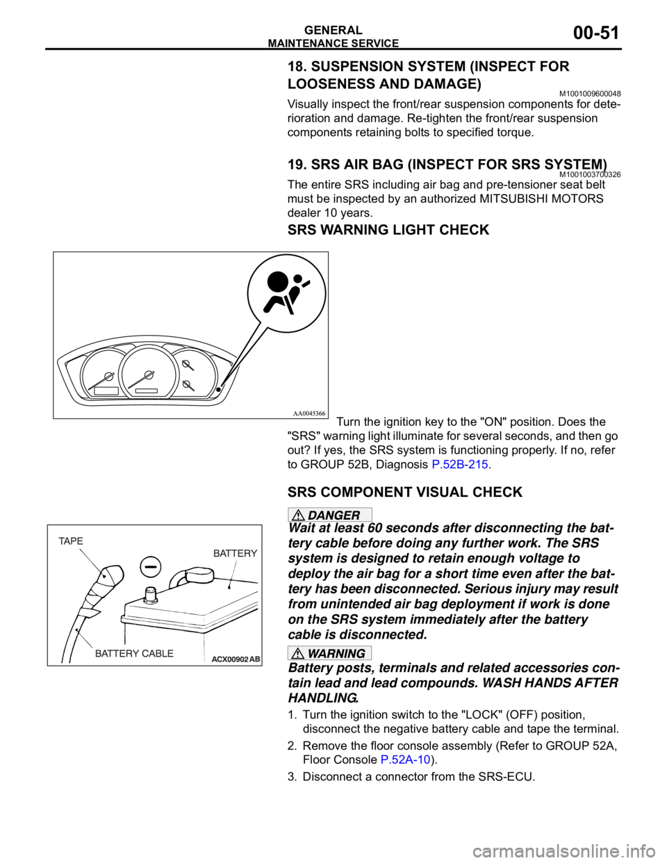
SRS WARNING LIGHT CHECK
Turn the ignition key to the "ON" position. Does the
"SRS" warning light illuminate for several seconds, and then go
out? If yes, the SRS system is functioning properly. If no, refer
to GROUP 52B, Diagnosis P.52B-215.
SRS COMPONENT VISUAL CHECK
Wait at least 60 seconds after disconnecting the bat-
tery cable before doing any further work. The SRS
system is designed to retain enough voltage to
deploy the air bag for a short time even after the bat-
tery has been disconnected. Serious injury may result
from unintended air bag deployment if work is done
on the SRS system immediately after the battery
cable is disconnected.
Battery posts, terminals and related accessories con-
tain lead and lead compounds. WASH HANDS AFTER
HANDLING.
1. Turn the ignition switch to the "LOCK" (OFF) position,
disconnect the negative battery cable and tape the terminal.
2. Remove the floor console assembly (Refer to GROUP 52A,
Floor Console P.52A-10).
3. Disconnect a connector from the SRS-ECU.
Page 1274 of 1500
MAINTENANCE SERVICE
GENERAL00-53
SRS AIR BAG CONTROL UNIT (SRS-ECU)
The SRS may not activate if the SRS-ECU is not
installed properly, which could result in serious injury
or death to the vehicle's driver and front passenger.
1. Check the SRS-ECU case for dents, cracks, deformation or
rust.
2. Check the connector for damage, and check the terminals
for deformation or rust.
Replace the SRS-ECU if it fails the visual checks above
(Refer to GROUP 52B, SRS Air Bag Control Unit
P.52B-234).
AIR BAG MODULE, STEERING WHEEL AND
CLOCK SPRING
The removed air bag module should be stored in a
clean, dry place with the pad cover face up.
Replace any visually inspected part if it fails the
following inspection.
1. Remove the air bag module, steering wheel and clock
spring.
(Refer to GROUP 52B, Air Bag Module and Clock Spring
P.52B-237).
2. Check the pad cover for dents, cracks or deformation.
Page 1275 of 1500

MAINTENANCE SERVICE
GENERAL00-54
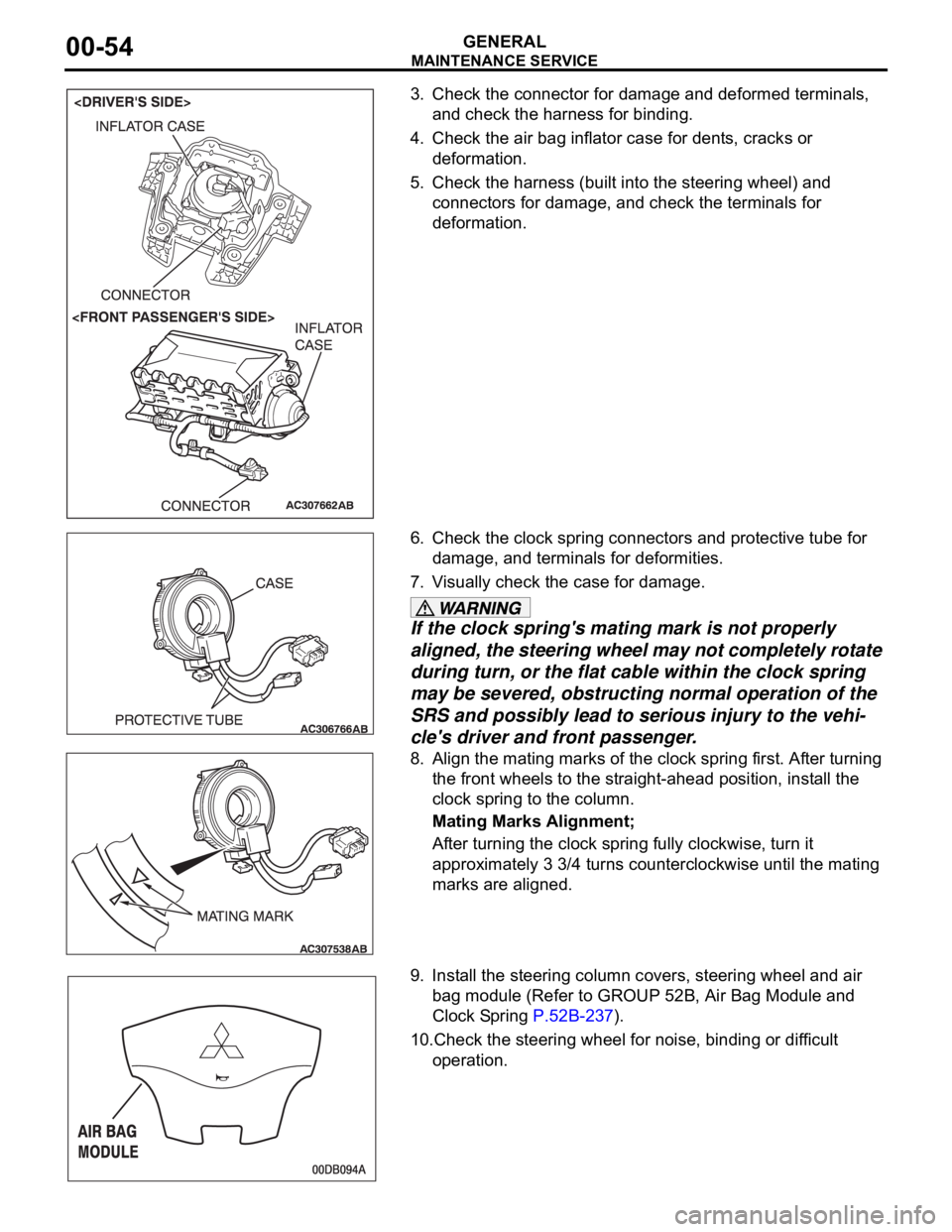
3. Check the connector for damage and deformed terminals,
and check the harness for binding.
4. Check the air bag inflator case for dents, cracks or
deformation.
5. Check the harness (built into the steering wheel) and
connectors for damage, and check the terminals for
deformation.
6. Check the clock spring connectors and protective tube for
damage, and terminals for deformities.
7. Visually check the case for damage.
If the clock spring's mating mark is not properly
aligned, the steering wheel may not completely rotate
during turn, or the flat cable within the clock spring
may be severed, obstructing normal operation of the
SRS and possibly lead to serious injury to the vehi-
cle's driver and front passenger.
8. Align the mating marks of the clock spring first. After turning
the front wheels to the straight-ahead position, install the
clock spring to the column.
Mating Marks Alignment;
After turning the clock spring fully clockwise, turn it
approximately 3 3/4 turns counterclockwise until the mating
marks are aligned.
9. Install the steering column covers, steering wheel and air
bag module (Refer to GROUP 52B, Air Bag Module and
Clock Spring P.52B-237).
10.Check the steering wheel for noise, binding or difficult
operation.