Page 1328 of 1500
TCL SWITCH
TRACTION CONTROL SYSTEM (TCL)13C-49
TCL SWITCH
REMOVAL AND INSTALLATIONM1136001600027
WHEEL SPEED SENSOR
REMOVAL AND INSTALLATIONM1136002500023
Refer to GROUP 35B, Wheel Speed Sensor P.35B-95.
ABS/TCL-ECU
REMOVAL AND INSTALLATIONM1136005300017
Replace the hydraulic unit (integrated with ABS/TCL-ECU). (Refer to GROUP 35B, Hydraulic Unit P.35B-93).
REMOVAL STEPS
HOOD LOCK RELEASE HANDLE
(REFER TO GROUP 42, HOOD P.42-8.)
INSTRUMENT LOWER PANEL (REFER
TO GROUP 52A, INSTRUMENT PANEL
ASSEMBLY P.52A-4.)
INSTRUMENT PANEL GARNISH
(REFER TO GROUP 52A,
INSTRUMENT PANEL ASSEMBLY
P.52A-4.)
1. SWITCH BEZEL ASSEMBLY
2. SWITCH PANEL ASSEMBLY
3. TCL SWITCH REMOVAL STEPS (Continued)
Page 1336 of 1500
ENGINE CONTROL
ENGINE AND EMISSION CONTROL17-5
DIAGNOSIS
Required Special Tools:
MB991958: Diagnostic Tool (MUT-III Sub Assembly)
MB991824: Vehicle Communication Interface (V.C.I.)
MB991827: MUT-III USB Cable
MB991910: MUT-III Main Harness A
STEP 1. Using Diagnostic Tool MB991958, read the
diagnostic trouble code (DTC).
To prevent damage to Diagnostic Tool MB991958, always
turn the ignition switch to the "LOCK" (OFF) position
before connecting or disconnecting Diagnostic Tool
MB991958.
(1) Ensure that the ignition switch is at the "LOCK" (OFF)
position.
(2) Start up the personal computer.
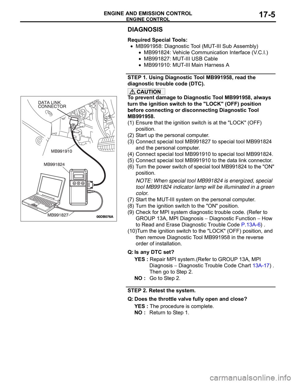
(3) Connect special tool MB991827 to special tool MB991824
and the personal computer.
(4) Connect special tool MB991910 to special tool MB991824.
(5) Connect special tool MB991910 to the data link connector.
(6) Turn the power switch of special tool MB991824 to the "ON"
position.
NOTE: When special tool MB991824 is energized, special
tool MB991824 indicator lamp will be illuminated in a green
color.
(7) Start the MUT-III system on the personal computer.
(8) Turn the ignition switch to the "ON" position.
(9) Check for MPI system diagnostic trouble code. (Refer to
GROUP 13A, MPI Diagnosis
Diagnostic Function How
to Read and Erase Diagnostic Trouble Code P.13A-6) .
(10)Turn the ignition switch to the "LOCK" (OFF) position, and
then remove Diagnostic Tool MB991958 in the reverse
order of installation.
Q: Is any DTC set?
YES : Repair MPI system.(Refer to GROUP 13A, MPI
Diagnosis
Diagnostic Trouble Code Chart 13A-17) .
Then go to Step 2.
NO : Go to Step 2.
STEP 2. Retest the system.
Q: Does the throttle valve fully open and close?
YES : The procedure is complete.
NO : Return to Step 1.
Page 1338 of 1500

ENGINE CONTROL
ENGINE AND EMISSION CONTROL17-7
STEP 2. Using Diagnostic Tool MB991958, read the
diagnostic trouble code (DTC).
To prevent damage to Diagnostic Tool MB991958, always
turn the ignition switch to the "LOCK" (OFF) position
before connecting or disconnecting Diagnostic Tool
MB991958.
(1) Ensure that the ignition switch is at the "LOCK" (OFF)
position.
(2) Start up the personal computer.
(3) Connect special tool MB991827 to special tool MB991824
and the personal computer.
(4) Connect special tool MB991910 to special tool MB991824.
(5) Connect special tool MB991910 to the data link connector.
(6) Turn the power switch of special tool MB991824 to the "ON"
position.
NOTE: When special tool MB991824 is energized, special
tool MB991824 indicator lamp will be illuminated in a green
color.
(7) Start the MUT-III system on the personal computer.
(8) Turn the ignition switch to the "ON" position.
(9) Check for MPI system diagnostic trouble code.(Refer to
GROUP 13A, MPI Diagnosis
Diagnostic Function How
to Read and Erase Diagnostic Trouble Code 13A-6) .
(10)Turn the ignition switch to the "LOCK" (OFF) position, and
then remove Diagnostic Tool MB991958 in the reverse
order of installation.
Q: Is any DTC set?
YES : Repair MPI system.(Refer to GROUP 13A, MPI
Diagnosis
Diagnostic Trouble Code Chart 13A-17) .
Then go to Step 3.
NO : Go to Step 3.
STEP 3. Retest the system.
Q: Does the accelerator pedal work normally?
YES : The procedure is complete.
NO : Return to Step 1.
Page 1343 of 1500
AUTO-CRUISE CONTROL
ENGINE AND EMISSION CONTROL17-12
To prevent damage to Diagnostic Tool MB991958, always
turn the ignition switch to the "LOCK" (OFF) position
before connecting or disconnecting Diagnostic Tool
MB991958.
1. Ensure that the ignition switch is at the "LOCK" (OFF)
position.
2. Start up the personal computer.
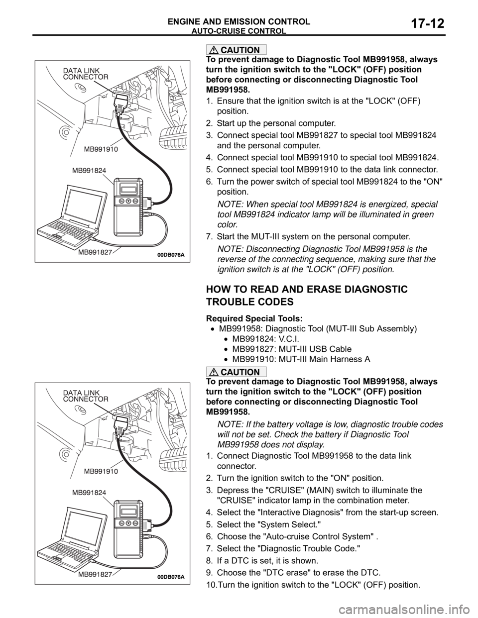
3. Connect special tool MB991827 to special tool MB991824
and the personal computer.
4. Connect special tool MB991910 to special tool MB991824.
5. Connect special tool MB991910 to the data link connector.
6. Turn the power switch of special tool MB991824 to the "ON"
position.
NOTE: When special tool MB991824 is energized, special
tool MB991824 indicator lamp will be illuminated in green
color.
7. Start the MUT-III system on the personal computer.
NOTE: Disconnecting Diagnostic Tool MB991958 is the
reverse of the connecting sequence, making sure that the
ignition switch is at the "LOCK" (OFF) position.
HOW TO READ AND ERASE DIAGNOSTIC
TROUBLE CODES
Required Special Tools:
MB991958: Diagnostic Tool (MUT-III Sub Assembly)
MB991824: V.C.I.
MB991827: MUT-III USB Cable
MB991910: MUT-III Main Harness A
To prevent damage to Diagnostic Tool MB991958, always
turn the ignition switch to the "LOCK" (OFF) position
before connecting or disconnecting Diagnostic Tool
MB991958.
NOTE: If the battery voltage is low, diagnostic trouble codes
will not be set. Check the battery if Diagnostic Tool
MB991958 does not display.
1. Connect Diagnostic Tool MB991958 to the data link
connector.
2. Turn the ignition switch to the "ON" position.
3. Depress the "CRUISE" (MAIN) switch to illuminate the
"CRUISE" indicator lamp in the combination meter.
4. Select the "Interactive Diagnosis" from the start-up screen.
5. Select the "System Select."
6. Choose the "Auto-cruise Control System" .
7. Select the "Diagnostic Trouble Code."
8. If a DTC is set, it is shown.
9. Choose the "DTC erase" to erase the DTC.
10.Turn the ignition switch to the "LOCK" (OFF) position.
Page 1344 of 1500
AUTO-CRUISE CONTROL
ENGINE AND EMISSION CONTROL17-13
11.Disconnect Diagnostic Tool MB991958.
HOW TO READ DATA LIST
Required Special Tools:
MB991958: Diagnostic Tool (MUT-III Sub Assembly)
MB991824: V.C.I.
MB991827: MUT-III USB Cable
MB991910: MUT-III Main Harness A
To prevent damage to Diagnostic Tool MB991958, always
turn the ignition switch to the "LOCK" (OFF) position
before connecting or disconnecting Diagnostic Tool
MB991958.
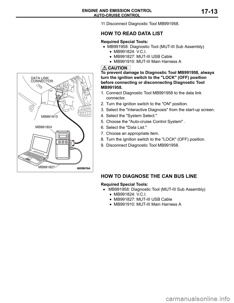
1. Connect Diagnostic Tool MB991958 to the data link
connector.
2. Turn the ignition switch to the "ON" position.
3. Select the "Interactive Diagnosis" from the start-up screen.
4. Select the "System Select."
5. Choose the "Auto-cruise Control System" .
6. Select the "Data List."
7. Choose an appropriate item.
8. Turn the ignition switch to the "LOCK" (OFF) position.
9. Disconnect Diagnostic Tool MB991958.
HOW TO DIAGNOSE THE CAN BUS LINE
Required Special Tools:
MB991958: Diagnostic Tool (MUT-III Sub Assembly)
MB991824: V.C.I.
MB991827: MUT-III USB Cable
MB991910: MUT-III Main Harness A
Page 1345 of 1500
AUTO-CRUISE CONTROL
ENGINE AND EMISSION CONTROL17-14
To prevent damage to Diagnostic Tool MB991958, always
turn the ignition switch to the "LOCK" (OFF) position
before connecting or disconnecting Diagnostic Tool
MB991958.
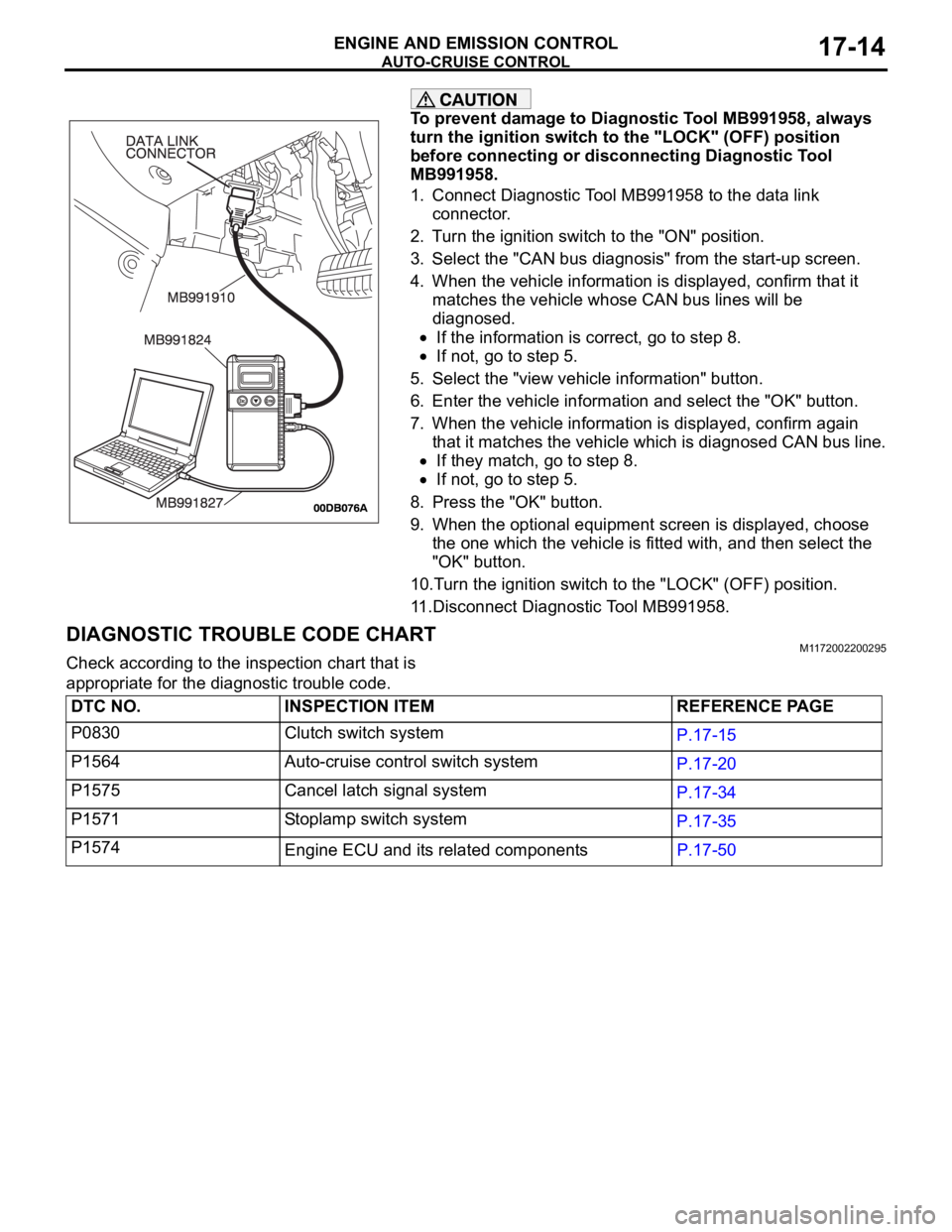
1. Connect Diagnostic Tool MB991958 to the data link
connector.
2. Turn the ignition switch to the "ON" position.
3. Select the "CAN bus diagnosis" from the start-up screen.
4. When the vehicle information is displayed, confirm that it
matches the vehicle whose CAN bus lines will be
diagnosed.
If the information is correct, go to step 8.
If not, go to step 5.
5. Select the "view vehicle information" button.
6. Enter the vehicle information and select the "OK" button.
7. When the vehicle information is displayed, confirm again
that it matches the vehicle which is diagnosed CAN bus line.
If they match, go to step 8.
If not, go to step 5.
8. Press the "OK" button.
9. When the optional equipment screen is displayed, choose
the one which the vehicle is fitted with, and then select the
"OK" button.
10.Turn the ignition switch to the "LOCK" (OFF) position.
11.Disconnect Diagnostic Tool MB991958.
DIAGNOSTIC TROUBLE CODE CHARTM1172002200295
Check according to the inspection chart that is
appropriate for the diagnostic trouble code.
DTC NO. INSPECTION ITEM REFERENCE PAGE
P0830 Clutch switch system
P.17-15
P1564 Auto-cruise control switch system
P.17-20
P1575 Cancel latch signal system
P.17-34
P1571 Stoplamp switch system
P.17-35
P1574
Engine ECU and its related componentsP.17-50
Page 1347 of 1500
AUTO-CRUISE CONTROL
ENGINE AND EMISSION CONTROL17-16
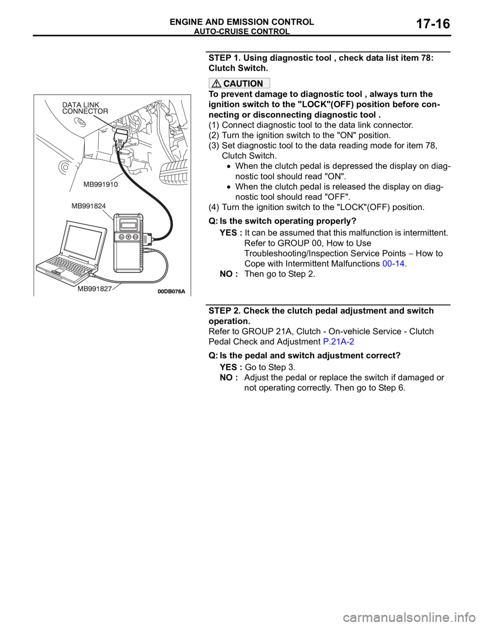
STEP 1. Using diagnostic tool , check data list item 78:
Clutch Switch.
To prevent damage to diagnostic tool , always turn the
ignition switch to the "LOCK"(OFF) position before con-
necting or disconnecting diagnostic tool .
(1) Connect diagnostic tool to the data link connector.
(2) Turn the ignition switch to the "ON" position.
(3) Set diagnostic tool to the data reading mode for item 78,
Clutch Switch.
When the clutch pedal is depressed the display on diag-
nostic tool should read "ON".
When the clutch pedal is released the display on diag-
nostic tool should read "OFF".
(4) Turn the ignition switch to the "LOCK"(OFF) position.
Q: Is the switch operating properly?
YES : It can be assumed that this malfunction is intermittent.
Refer to GROUP 00, How to Use
Troubleshooting/Inspection Service Points
How to
Cope with Intermittent Malfunctions 00-14.
NO : Then go to Step 2.
STEP 2. Check the clutch pedal adjustment and switch
operation.
Refer to GROUP 21A, Clutch - On-vehicle Service - Clutch
Pedal Check and Adjustment P.21A-2
Q: Is the pedal and switch adjustment correct?
YES : Go to Step 3.
NO : Adjust the pedal or replace the switch if damaged or
not operating correctly. Then go to Step 6.
Page 1349 of 1500
AUTO-CRUISE CONTROL
ENGINE AND EMISSION CONTROL17-18
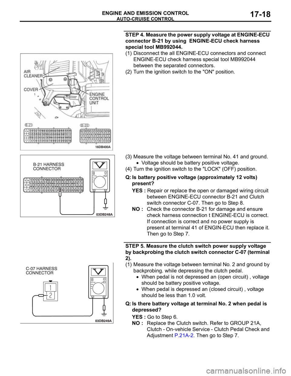
STEP 4. Measure the power supply voltage at ENGINE-ECU
connector B-21 by using ENGINE-ECU check harness
special tool MB992044.
(1) Disconnect the all ENGINE-ECU connectors and connect
ENGINE-ECU check harness special tool MB992044
between the separated connectors.
(2) Turn the ignition switch to the "ON" position.
(3) Measure the voltage between terminal No. 41 and ground.
Voltage should be battery positive voltage.
(4) Turn the ignition switch to the "LOCK" (OFF) position.
Q: Is battery positive voltage (approximately 12 volts)
present?
YES : Repair or replace the open or damaged wiring circuit
between ENGINE-ECU connector B-21 and Clutch
switch connector C-07. Then go to Step 8.
NO : Check the connector B-21 for damage and ensure
check harness connection t ENGINE-ECU is correct.
If connection is correct and no power supply is
present at terminal 41 of ENGIN-ECU then replace it.
Then go to Step 7.
STEP 5. Measure the clutch switch power supply voltage
by backprobing the clutch switch connector C-07 (terminal
2).
(1) Measure the voltage between terminal No. 2 and ground by
backprobing. while depressing the clutch pedal.
When pedal is not depressed an (open circuit) , voltage
should be battery positive voltage.
When pedal is depressed an (closed circuit) , voltage
should be less than 1.0 volt.
Q: Is there battery voltage at terminal No. 2 when pedal is
depressed?
YES : Go to Step 6.
NO : Replace the Clutch switch. Refer to GROUP 21A,
Clutch - On-vehicle Service - Clutch Pedal Check and
Adjustment P.21A-2. Then go to Step 7.