2005 MERCEDES-BENZ SPRINTER timing belt
[x] Cancel search: timing beltPage 806 of 1232
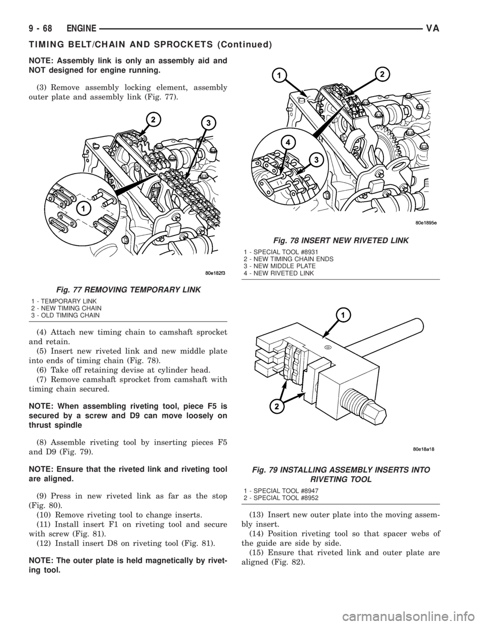
NOTE: Assembly link is only an assembly aid and
NOT designed for engine running.
(3) Remove assembly locking element, assembly
outer plate and assembly link (Fig. 77).
(4) Attach new timing chain to camshaft sprocket
and retain.
(5) Insert new riveted link and new middle plate
into ends of timing chain (Fig. 78).
(6) Take off retaining devise at cylinder head.
(7) Remove camshaft sprocket from camshaft with
timing chain secured.
NOTE: When assembling riveting tool, piece F5 is
secured by a screw and D9 can move loosely on
thrust spindle
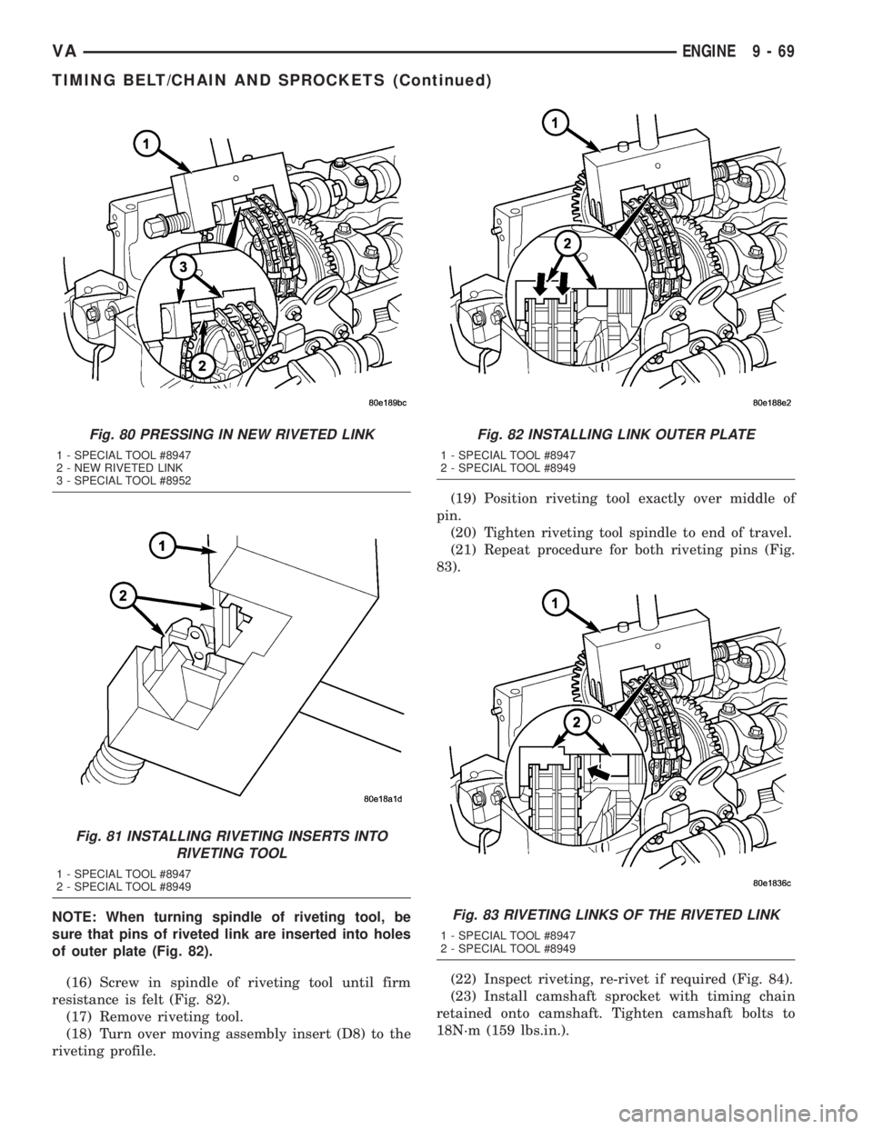
(8) Assemble riveting tool by inserting pieces F5
and D9 (Fig. 79).
NOTE: Ensure that the riveted link and riveting tool
are aligned.
(9) Press in new riveted link as far as the stop
(Fig. 80).
(10) Remove riveting tool to change inserts.
(11) Install insert F1 on riveting tool and secure
with screw (Fig. 81).
(12) Install insert D8 on riveting tool (Fig. 81).
NOTE: The outer plate is held magnetically by rivet-
ing tool.(13) Insert new outer plate into the moving assem-
bly insert.
(14) Position riveting tool so that spacer webs of
the guide are side by side.
(15) Ensure that riveted link and outer plate are
aligned (Fig. 82).
Fig. 77 REMOVING TEMPORARY LINK
1 - TEMPORARY LINK
2 - NEW TIMING CHAIN
3 - OLD TIMING CHAIN
Fig. 78 INSERT NEW RIVETED LINK
1 - SPECIAL TOOL #8931
2 - NEW TIMING CHAIN ENDS
3 - NEW MIDDLE PLATE
4 - NEW RIVETED LINK
Fig. 79 INSTALLING ASSEMBLY INSERTS INTO
RIVETING TOOL
1 - SPECIAL TOOL #8947
2 - SPECIAL TOOL #8952
9 - 68 ENGINEVA
TIMING BELT/CHAIN AND SPROCKETS (Continued)
Page 807 of 1232
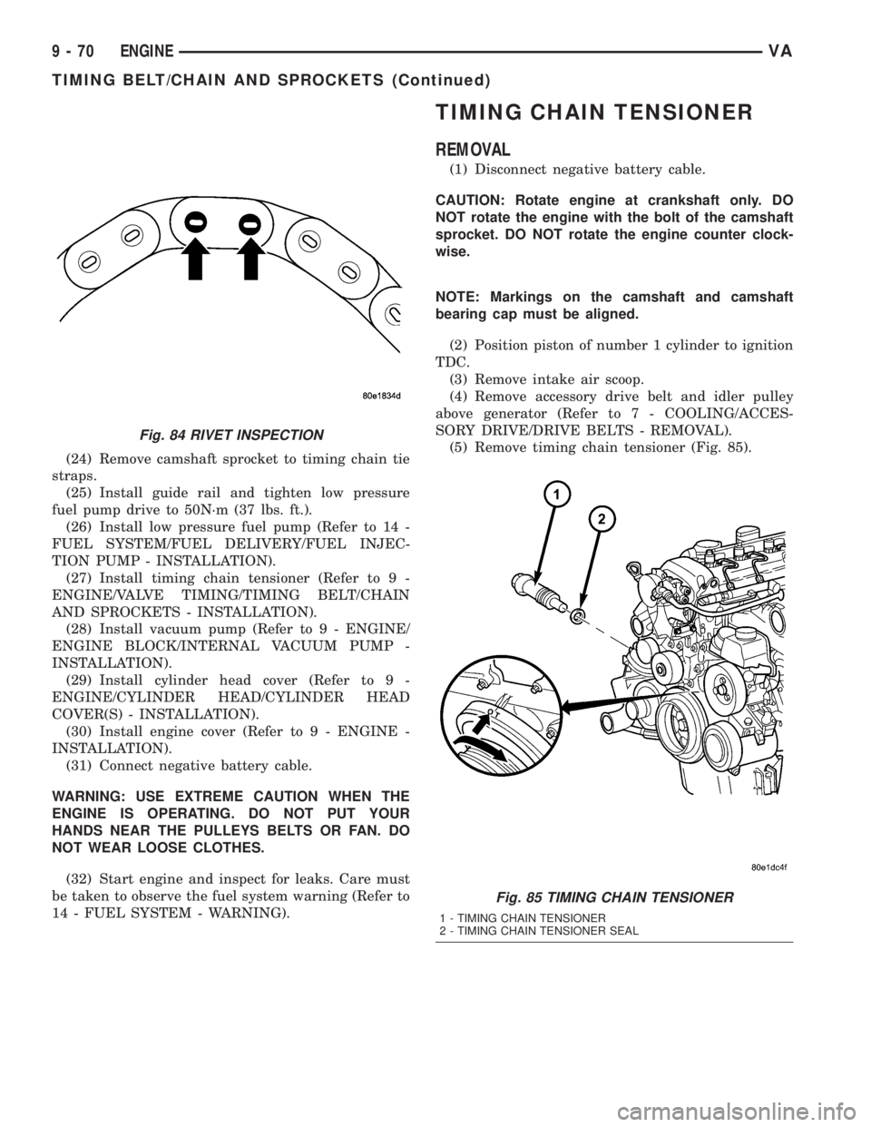
NOTE: When turning spindle of riveting tool, be
sure that pins of riveted link are inserted into holes
of outer plate (Fig. 82).
(16) Screw in spindle of riveting tool until firm
resistance is felt (Fig. 82).
(17) Remove riveting tool.
(18) Turn over moving assembly insert (D8) to the
riveting profile.(19) Position riveting tool exactly over middle of
pin.
(20) Tighten riveting tool spindle to end of travel.
(21) Repeat procedure for both riveting pins (Fig.
83).
(22) Inspect riveting, re-rivet if required (Fig. 84).
(23) Install camshaft sprocket with timing chain
retained onto camshaft. Tighten camshaft bolts to
18N´m (159 lbs.in.).
Fig. 80 PRESSING IN NEW RIVETED LINK
1 - SPECIAL TOOL #8947
2 - NEW RIVETED LINK
3 - SPECIAL TOOL #8952
Fig. 81 INSTALLING RIVETING INSERTS INTO
RIVETING TOOL
1 - SPECIAL TOOL #8947
2 - SPECIAL TOOL #8949
Fig. 82 INSTALLING LINK OUTER PLATE
1 - SPECIAL TOOL #8947
2 - SPECIAL TOOL #8949
Fig. 83 RIVETING LINKS OF THE RIVETED LINK
1 - SPECIAL TOOL #8947
2 - SPECIAL TOOL #8949
VAENGINE 9 - 69
TIMING BELT/CHAIN AND SPROCKETS (Continued)
Page 808 of 1232
(24) Remove camshaft sprocket to timing chain tie
straps.
(25) Install guide rail and tighten low pressure
fuel pump drive to 50N´m (37 lbs. ft.).
(26) Install low pressure fuel pump (Refer to 14 -
FUEL SYSTEM/FUEL DELIVERY/FUEL INJEC-
TION PUMP - INSTALLATION).
(27) Install timing chain tensioner (Refer to 9 -
ENGINE/VALVE TIMING/TIMING BELT/CHAIN
AND SPROCKETS - INSTALLATION).
(28) Install vacuum pump (Refer to 9 - ENGINE/
ENGINE BLOCK/INTERNAL VACUUM PUMP -
INSTALLATION).
(29) Install cylinder head cover (Refer to 9 -
ENGINE/CYLINDER HEAD/CYLINDER HEAD
COVER(S) - INSTALLATION).
(30) Install engine cover (Refer to 9 - ENGINE -
INSTALLATION).
(31) Connect negative battery cable.
WARNING: USE EXTREME CAUTION WHEN THE
ENGINE IS OPERATING. DO NOT PUT YOUR
HANDS NEAR THE PULLEYS BELTS OR FAN. DO
NOT WEAR LOOSE CLOTHES.
(32) Start engine and inspect for leaks. Care must
be taken to observe the fuel system warning (Refer to
14 - FUEL SYSTEM - WARNING).
TIMING CHAIN TENSIONER
REMOVAL
(1) Disconnect negative battery cable.
CAUTION: Rotate engine at crankshaft only. DO
NOT rotate the engine with the bolt of the camshaft
sprocket. DO NOT rotate the engine counter clock-
wise.
NOTE: Markings on the camshaft and camshaft
bearing cap must be aligned.
(2) Position piston of number 1 cylinder to ignition
TDC.
(3) Remove intake air scoop.
(4) Remove accessory drive belt and idler pulley
above generator (Refer to 7 - COOLING/ACCES-
SORY DRIVE/DRIVE BELTS - REMOVAL).
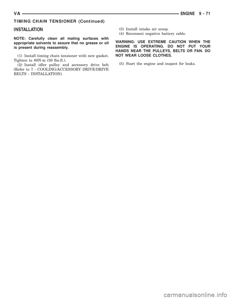
(5) Remove timing chain tensioner (Fig. 85).
Fig. 84 RIVET INSPECTION
Fig. 85 TIMING CHAIN TENSIONER
1 - TIMING CHAIN TENSIONER
2 - TIMING CHAIN TENSIONER SEAL
9 - 70 ENGINEVA
TIMING BELT/CHAIN AND SPROCKETS (Continued)
Page 809 of 1232
INSTALLATION
NOTE: Carefully clean all mating surfaces with
appropriate solvents to assure that no grease or oil
is present during reassembly.
(1) Install timing chain tensioner with new gasket.
Tighten to 80N´m (59 lbs.ft.).
(2) Install idler pulley and accessory drive belt
(Refer to 7 - COOLING/ACCESSORY DRIVE/DRIVE
BELTS - INSTALLATION).(3) Install intake air scoop.
(4) Reconnect negative battery cable.
WARNING: USE EXTREME CAUTION WHEN THE
ENGINE IS OPERATING. DO NOT PUT YOUR
HANDS NEAR THE PULLEYS, BELTS OR FAN. DO
NOT WEAR LOOSE CLOTHES.
(5) Start the engine and inspect for leaks.
VAENGINE 9 - 71
TIMING CHAIN TENSIONER (Continued)
Page 1213 of 1232
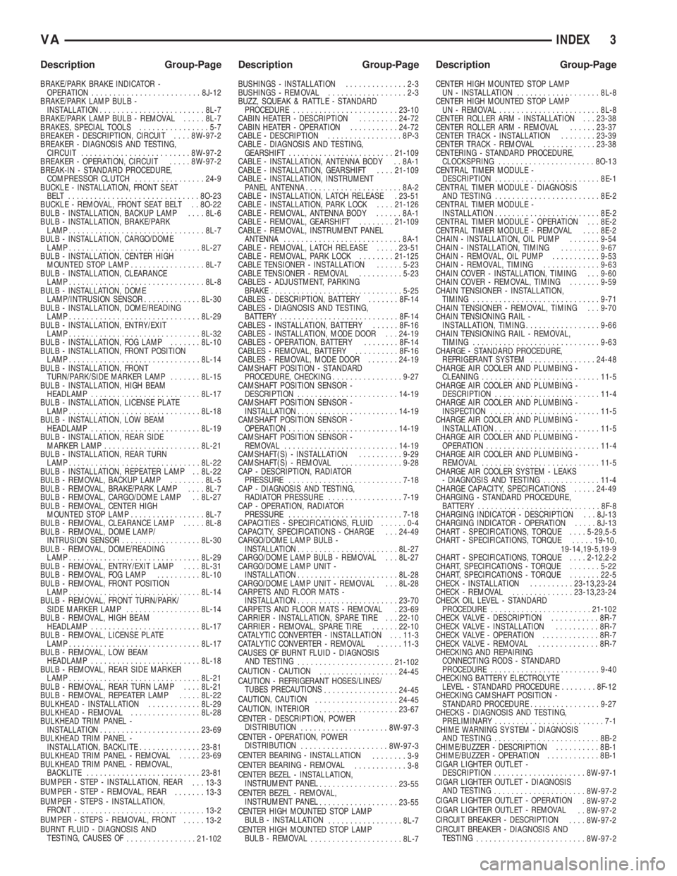
BRAKE/PARK BRAKE INDICATOR -
OPERATION.........................8J-12
BRAKE/PARK LAMP BULB -
INSTALLATION........................8L-7
BRAKE/PARK LAMP BULB - REMOVAL.....8L-7
BRAKES, SPECIAL TOOLS................5-7
BREAKER - DESCRIPTION, CIRCUIT....8W-97-2
BREAKER - DIAGNOSIS AND TESTING,
CIRCUIT.........................8W-97-2
BREAKER - OPERATION, CIRCUIT.....8W-97-2
BREAK-IN - STANDARD PROCEDURE,
COMPRESSOR CLUTCH................24-9
BUCKLE - INSTALLATION, FRONT SEAT
BELT ..............................8O-23
BUCKLE - REMOVAL, FRONT SEAT BELT . . 8O-22
BULB - INSTALLATION, BACKUP LAMP....8L-6
BULB - INSTALLATION, BRAKE/PARK
LAMP...............................8L-7
BULB - INSTALLATION, CARGO/DOME
LAMP..............................8L-27
BULB - INSTALLATION, CENTER HIGH
MOUNTED STOP LAMP.................8L-7
BULB - INSTALLATION, CLEARANCE
LAMP...............................8L-8
BULB - INSTALLATION, DOME
LAMP/INTRUSION SENSOR.............8L-30
BULB - INSTALLATION, DOME/READING
LAMP..............................8L-29
BULB - INSTALLATION, ENTRY/EXIT
LAMP..............................8L-32
BULB - INSTALLATION, FOG LAMP.......8L-10
BULB - INSTALLATION, FRONT POSITION
LAMP..............................8L-14
BULB - INSTALLATION, FRONT
TURN/PARK/SIDE MARKER LAMP.......8L-15
BULB - INSTALLATION, HIGH BEAM
HEADLAMP.........................8L-17
BULB - INSTALLATION, LICENSE PLATE
LAMP..............................8L-18
BULB - INSTALLATION, LOW BEAM
HEADLAMP.........................8L-19
BULB - INSTALLATION, REAR SIDE
MARKER LAMP......................8L-21
BULB - INSTALLATION, REAR TURN
LAMP..............................8L-22
BULB - INSTALLATION, REPEATER LAMP . . 8L-22
BULB - REMOVAL, BACKUP LAMP........8L-5
BULB - REMOVAL, BRAKE/PARK LAMP....8L-7
BULB - REMOVAL, CARGO/DOME LAMP . . 8L-27
BULB - REMOVAL, CENTER HIGH
MOUNTED STOP LAMP.................8L-7
BULB - REMOVAL, CLEARANCE LAMP.....8L-8
BULB - REMOVAL, DOME LAMP/
INTRUSION SENSOR..................8L-30
BULB - REMOVAL, DOME/READING
LAMP..............................8L-29
BULB - REMOVAL, ENTRY/EXIT LAMP....8L-31
BULB - REMOVAL, FOG LAMP..........8L-10
BULB - REMOVAL, FRONT POSITION
LAMP..............................8L-14
BULB - REMOVAL, FRONT TURN/PARK/
SIDE MARKER LAMP.................8L-14
BULB - REMOVAL, HIGH BEAM
HEADLAMP.........................8L-17
BULB - REMOVAL, LICENSE PLATE
LAMP..............................8L-17
BULB - REMOVAL, LOW BEAM
HEADLAMP.........................8L-18
BULB - REMOVAL, REAR SIDE MARKER
LAMP..............................8L-21
BULB - REMOVAL, REAR TURN LAMP....8L-21
BULB - REMOVAL, REPEATER LAMP.....8L-22
BULKHEAD - INSTALLATION............8L-29
BULKHEAD - REMOVAL................8L-28
BULKHEAD TRIM PANEL -
INSTALLATION.......................23-69
BULKHEAD TRIM PANEL -
INSTALLATION, BACKLITE..............23-81
BULKHEAD TRIM PANEL - REMOVAL.....23-69
BULKHEAD TRIM PANEL - REMOVAL,
BACKLITE..........................23-81
BUMPER - STEP - INSTALLATION, REAR
. . . 13-3
BUMPER - STEP - REMOVAL, REAR
.......13-3
BUMPER - STEPS - INSTALLATION,
FRONT
..............................13-2
BUMPER - STEPS - REMOVAL, FRONT
.....13-2
BURNT FLUID - DIAGNOSIS AND
TESTING, CAUSES OF
................21-102BUSHINGS - INSTALLATION..............2-3
BUSHINGS - REMOVAL..................2-3
BUZZ, SQUEAK & RATTLE - STANDARD
PROCEDURE........................23-10
CABIN HEATER - DESCRIPTION.........24-72
CABIN HEATER - OPERATION...........24-72
CABLE - DESCRIPTION.................8P-3
CABLE - DIAGNOSIS AND TESTING,
GEARSHIFT........................21-109
CABLE - INSTALLATION, ANTENNA BODY . . 8A-1
CABLE - INSTALLATION, GEARSHIFT....21-109
CABLE - INSTALLATION, INSTRUMENT
PANEL ANTENNA......................8A-2
CABLE - INSTALLATION, LATCH RELEASE . 23-51
CABLE - INSTALLATION, PARK LOCK....21-126
CABLE - REMOVAL, ANTENNA BODY......8A-1
CABLE - REMOVAL, GEARSHIFT........21-109
CABLE - REMOVAL, INSTRUMENT PANEL
ANTENNA...........................8A-1
CABLE - REMOVAL, LATCH RELEASE.....23-51
CABLE - REMOVAL, PARK LOCK........21-125
CABLE TENSIONER - INSTALLATION......5-23
CABLE TENSIONER - REMOVAL..........5-23
CABLES - ADJUSTMENT, PARKING
BRAKE..............................5-25
CABLES - DESCRIPTION, BATTERY.......8F-14
CABLES - DIAGNOSIS AND TESTING,
BATTERY...........................8F-14
CABLES - INSTALLATION, BATTERY......8F-16
CABLES - INSTALLATION, MODE DOOR . . . 24-19
CABLES - OPERATION, BATTERY........8F-14
CABLES - REMOVAL, BATTERY..........8F-16
CABLES - REMOVAL, MODE DOOR.......24-19
CAMSHAFT POSITION - STANDARD
PROCEDURE, CHECKING................9-27
CAMSHAFT POSITION SENSOR -
DESCRIPTION.......................14-19
CAMSHAFT POSITION SENSOR -
INSTALLATION.......................14-19
CAMSHAFT POSITION SENSOR -
OPERATION.........................14-19
CAMSHAFT POSITION SENSOR -
REMOVAL..........................14-19
CAMSHAFT(S) - INSTALLATION..........9-29
CAMSHAFT(S) - REMOVAL..............9-28
CAP - DESCRIPTION, RADIATOR
PRESSURE..........................7-18
CAP - DIAGNOSIS AND TESTING,
RADIATOR PRESSURE.................7-19
CAP - OPERATION, RADIATOR
PRESSURE..........................7-18
CAPACITIES - SPECIFICATIONS, FLUID......0-4
CAPACITY, SPECIFICATIONS - CHARGE . . . 24-49
CARGO/DOME LAMP BULB -
INSTALLATION.......................8L-27
CARGO/DOME LAMP BULB - REMOVAL . . . 8L-27
CARGO/DOME LAMP UNIT -
INSTALLATION.......................8L-28
CARGO/DOME LAMP UNIT - REMOVAL . . . 8L-28
CARPETS AND FLOOR MATS -
INSTALLATION.......................23-70
CARPETS AND FLOOR MATS - REMOVAL . 23-69
CARRIER - INSTALLATION, SPARE TIRE . . . 22-10
CARRIER - REMOVAL, SPARE TIRE......22-10
CATALYTIC CONVERTER - INSTALLATION . . . 11-3
CATALYTIC CONVERTER - REMOVAL......11-3
CAUSES OF BURNT FLUID - DIAGNOSIS
AND TESTING
......................21-102
CAUTION - CAUTION
..................24-45
CAUTION - REFRIGERANT HOSES/LINES/
TUBES PRECAUTIONS
.................24-45
CAUTION, CAUTION
...................24-45
CAUTION, INTERIOR
..................23-67
CENTER - DESCRIPTION, POWER
DISTRIBUTION
....................8W-97-3
CENTER - OPERATION, POWER
DISTRIBUTION
....................8W-97-3
CENTER BEARING - INSTALLATION
........3-9
CENTER BEARING - REMOVAL
............3-8
CENTER BEZEL - INSTALLATION,
INSTRUMENT PANEL
..................23-55
CENTER BEZEL - REMOVAL,
INSTRUMENT PANEL
..................23-55
CENTER HIGH MOUNTED STOP LAMP
BULB - INSTALLATION
.................8L-7
CENTER HIGH MOUNTED STOP LAMP
BULB - REMOVAL
.....................8L-7CENTER HIGH MOUNTED STOP LAMP
UN - INSTALLATION...................8L-8
CENTER HIGH MOUNTED STOP LAMP
UN - REMOVAL.......................8L-8
CENTER ROLLER ARM - INSTALLATION . . . 23-38
CENTER ROLLER ARM - REMOVAL......23-37
CENTER TRACK - INSTALLATION........23-39
CENTER TRACK - REMOVAL............23-38
CENTERING - STANDARD PROCEDURE,
CLOCKSPRING......................8O-13
CENTRAL TIMER MODULE -
DESCRIPTION........................8E-1
CENTRAL TIMER MODULE - DIAGNOSIS
AND TESTING........................8E-2
CENTRAL TIMER MODULE -
INSTALLATION........................8E-2
CENTRAL TIMER MODULE - OPERATION . . . 8E-2
CENTRAL TIMER MODULE - REMOVAL....8E-2
CHAIN - INSTALLATION, OIL PUMP.......9-54
CHAIN - INSTALLATION, TIMING.........9-67
CHAIN - REMOVAL, OIL PUMP...........9-53
CHAIN - REMOVAL, TIMING.............9-63
CHAIN COVER - INSTALLATION, TIMING . . . 9-60
CHAIN COVER - REMOVAL, TIMING.......9-59
CHAIN TENSIONER - INSTALLATION,
TIMING.............................9-71
CHAIN TENSIONER - REMOVAL, TIMING . . . 9-70
CHAIN TENSIONING RAIL -
INSTALLATION, TIMING.................9-66
CHAIN TENSIONING RAIL - REMOVAL,
TIMING.............................9-63
CHARGE - STANDARD PROCEDURE,
REFRIGERANT SYSTEM...............24-48
CHARGE AIR COOLER AND PLUMBING -
CLEANING...........................11-5
CHARGE AIR COOLER AND PLUMBING -
DESCRIPTION........................11-4
CHARGE AIR COOLER AND PLUMBING -
INSPECTION.........................11-5
CHARGE AIR COOLER AND PLUMBING -
INSTALLATION........................11-5
CHARGE AIR COOLER AND PLUMBING -
OPERATION..........................11-4
CHARGE AIR COOLER AND PLUMBING -
REMOVAL...........................11-5
CHARGE AIR COOLER SYSTEM - LEAKS
- DIAGNOSIS AND TESTING.............11-4
CHARGE CAPACITY, SPECIFICATIONS.....24-49
CHARGING - STANDARD PROCEDURE,
BATTERY............................8F-8
CHARGING INDICATOR - DESCRIPTION . . . 8J-13
CHARGING INDICATOR - OPERATION.....8J-13
CHART - SPECIFICATIONS, TORQUE....5-29,5-5
CHART - SPECIFICATIONS, TORQUE.....19-10,
19-14,19-5,19-9
CHART - SPECIFICATIONS, TORQUE....2-12,2-2
CHART, SPECIFICATIONS - TORQUE.......5-22
CHART, SPECIFICATIONS - TORQUE.......22-5
CHECK - INSTALLATION..........23-13,23-24
CHECK - REMOVAL..............23-13,23-24
CHECK OIL LEVEL - STANDARD
PROCEDURE.......................21-102
CHECK VALVE - DESCRIPTION...........8R-7
CHECK VALVE - INSTALLATION..........8R-7
CHECK VALVE - OPERATION.............8R-7
CHECK VALVE - REMOVAL..............8R-7
CHECKING AND REPAIRING
CONNECTING RODS - STANDARD
PROCEDURE.........................9-40
CHECKING BATTERY ELECTROLYTE
LEVEL - STANDARD PROCEDURE........8F-12
CHECKING CAMSHAFT POSITION -
STANDARD PROCEDURE................9-27
CHECKS - DIAGNOSIS AND TESTING,
PRELIMINARY.........................7-1
CHIME WARNING SYSTEM - DIAGNOSIS
AND TESTING........................8B-2
CHIME/BUZZER - DESCRIPTION..........8B-1
CHIME/BUZZER - OPERATION............8B-1
CIGAR LIGHTER OUTLET -
DESCRIPTION.....................8W-97-1
CIGAR LIGHTER OUTLET - DIAGNOSIS
AND TESTING
.....................8W-97-2
CIGAR LIGHTER OUTLET - OPERATION
. 8W-97-2
CIGAR LIGHTER OUTLET - REMOVAL
. . 8W-97-2
CIRCUIT BREAKER - DESCRIPTION
....8W-97-2
CIRCUIT BREAKER - DIAGNOSIS AND
TESTING
.........................8W-97-2
VAINDEX 3
Description Group-Page Description Group-Page Description Group-Page
Page 1215 of 1232
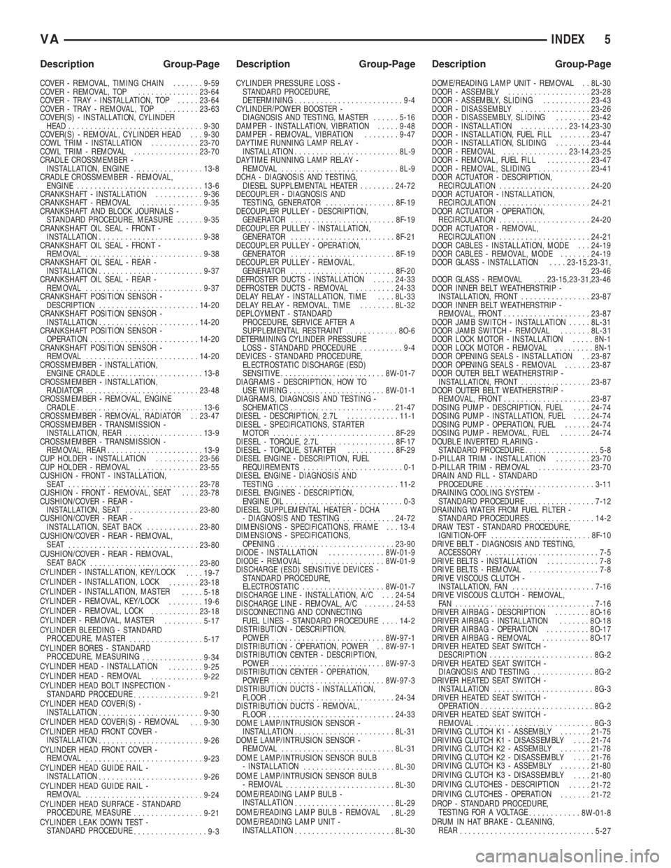
COVER - REMOVAL, TIMING CHAIN.......9-59
COVER - REMOVAL, TOP..............23-64
COVER - TRAY - INSTALLATION, TOP.....23-64
COVER - TRAY - REMOVAL, TOP........23-63
COVER(S) - INSTALLATION, CYLINDER
HEAD...............................9-30
COVER(S) - REMOVAL, CYLINDER HEAD . . . 9-30
COWL TRIM - INSTALLATION...........23-70
COWL TRIM - REMOVAL...............23-70
CRADLE CROSSMEMBER -
INSTALLATION, ENGINE................13-8
CRADLE CROSSMEMBER - REMOVAL,
ENGINE.............................13-6
CRANKSHAFT - INSTALLATION...........9-36
CRANKSHAFT - REMOVAL..............9-35
CRANKSHAFT AND BLOCK JOURNALS -
STANDARD PROCEDURE, MEASURE......9-35
CRANKSHAFT OIL SEAL - FRONT -
INSTALLATION........................9-38
CRANKSHAFT OIL SEAL - FRONT -
REMOVAL...........................9-38
CRANKSHAFT OIL SEAL - REAR -
INSTALLATION........................9-37
CRANKSHAFT OIL SEAL - REAR -
REMOVAL...........................9-37
CRANKSHAFT POSITION SENSOR -
DESCRIPTION.......................14-20
CRANKSHAFT POSITION SENSOR -
INSTALLATION.......................14-20
CRANKSHAFT POSITION SENSOR -
OPERATION..........................14-20
CRANKSHAFT POSITION SENSOR -
REMOVAL..........................14-20
CROSSMEMBER - INSTALLATION,
ENGINE CRADLE......................13-8
CROSSMEMBER - INSTALLATION,
RADIATOR..........................23-48
CROSSMEMBER - REMOVAL, ENGINE
CRADLE.............................13-6
CROSSMEMBER - REMOVAL, RADIATOR . . 23-47
CROSSMEMBER - TRANSMISSION -
INSTALLATION, REAR..................13-9
CROSSMEMBER - TRANSMISSION -
REMOVAL, REAR......................13-9
CUP HOLDER - INSTALLATION..........23-56
CUP HOLDER - REMOVAL..............23-55
CUSHION - FRONT - INSTALLATION,
SEAT ..............................23-78
CUSHION - FRONT - REMOVAL, SEAT....23-78
CUSHION/COVER - REAR -
INSTALLATION, SEAT.................23-80
CUSHION/COVER - REAR -
INSTALLATION, SEAT BACK............23-80
CUSHION/COVER - REAR - REMOVAL,
SEAT
..............................23-80
CUSHION/COVER - REAR - REMOVAL,
SEAT BACK
.........................23-80
CYLINDER - INSTALLATION, KEY/LOCK
....19-7
CYLINDER - INSTALLATION, LOCK
.......23-18
CYLINDER - INSTALLATION, MASTER
.....5-18
CYLINDER - REMOVAL, KEY/LOCK
........19-6
CYLINDER - REMOVAL, LOCK
...........23-18
CYLINDER - REMOVAL, MASTER
.........5-17
CYLINDER BLEEDING - STANDARD
PROCEDURE, MASTER
.................5-17
CYLINDER BORES - STANDARD
PROCEDURE, MEASURING
..............9-34
CYLINDER HEAD - INSTALLATION
........9-25
CYLINDER HEAD - REMOVAL
............9-22
CYLINDER HEAD BOLT INSPECTION -
STANDARD PROCEDURE
................9-21
CYLINDER HEAD COVER(S) -
INSTALLATION
........................9-30
CYLINDER HEAD COVER(S) - REMOVAL
. . . 9-30
CYLINDER HEAD FRONT COVER -
INSTALLATION
........................9-26
CYLINDER HEAD FRONT COVER -
REMOVAL
...........................9-23
CYLINDER HEAD GUIDE RAIL -
INSTALLATION
........................9-26
CYLINDER HEAD GUIDE RAIL -
REMOVAL
...........................9-24
CYLINDER HEAD SURFACE - STANDARD
PROCEDURE, MEASURE
................9-21
CYLINDER LEAK DOWN TEST -
STANDARD PROCEDURE
.................9-3CYLINDER PRESSURE LOSS -
STANDARD PROCEDURE,
DETERMINING.........................9-4
CYLINDER/POWER BOOSTER -
DIAGNOSIS AND TESTING, MASTER......5-16
DAMPER - INSTALLATION, VIBRATION.....9-48
DAMPER - REMOVAL, VIBRATION........9-47
DAYTIME RUNNING LAMP RELAY -
INSTALLATION........................8L-9
DAYTIME RUNNING LAMP RELAY -
REMOVAL...........................8L-9
DCHA - DIAGNOSIS AND TESTING,
DIESEL SUPPLEMENTAL HEATER........24-72
DECOUPLER - DIAGNOSIS AND
TESTING, GENERATOR................8F-19
DECOUPLER PULLEY - DESCRIPTION,
GENERATOR........................8F-19
DECOUPLER PULLEY - INSTALLATION,
GENERATOR........................8F-21
DECOUPLER PULLEY - OPERATION,
GENERATOR........................8F-19
DECOUPLER PULLEY - REMOVAL,
GENERATOR........................8F-20
DEFROSTER DUCTS - INSTALLATION.....24-33
DEFROSTER DUCTS - REMOVAL.........24-33
DELAY RELAY - INSTALLATION, TIME....8L-33
DELAY RELAY - REMOVAL, TIME........8L-32
DEPLOYMENT - STANDARD
PROCEDURE, SERVICE AFTER A
SUPPLEMENTAL RESTRAINT............8O-6
DETERMINING CYLINDER PRESSURE
LOSS - STANDARD PROCEDURE..........9-4
DEVICES - STANDARD PROCEDURE,
ELECTROSTATIC DISCHARGE (ESD)
SENSITIVE........................8W-01-7
DIAGRAMS - DESCRIPTION, HOW TO
USE WIRING......................8W-01-1
DIAGRAMS, DIAGNOSIS AND TESTING -
SCHEMATICS........................21-47
DIESEL - DESCRIPTION, 2.7L............11-1
DIESEL - SPECIFICATIONS, STARTER
MOTOR............................8F-29
DIESEL - TORQUE, 2.7L...............8F-17
DIESEL - TORQUE, STARTER...........8F-29
DIESEL ENGINE - DESCRIPTION, FUEL
REQUIREMENTS.......................0-1
DIESEL ENGINE - DIAGNOSIS AND
TESTING............................11-2
DIESEL ENGINES - DESCRIPTION,
ENGINE OIL...........................0-3
DIESEL SUPPLEMENTAL HEATER - DCHA
- DIAGNOSIS AND TESTING............24-72
DIMENSIONS - SPECIFICATIONS, FRAME . . . 13-4
DIMENSIONS - SPECIFICATIONS,
OPENING...........................23-90
DIODE - INSTALLATION.............8W-01-9
DIODE - REMOVAL.................8W-01-9
DISCHARGE (ESD) SENSITIVE DEVICES -
STANDARD PROCEDURE,
ELECTROSTATIC...................8W-01-7
DISCHARGE LINE - INSTALLATION, A/C . . . 24-54
DISCHARGE LINE - REMOVAL, A/C.......24-53
DISCONNECTING AND CONNECTING
FUEL LINES - STANDARD PROCEDURE....14-2
DISTRIBUTION - DESCRIPTION,
POWER..........................8W-97-1
DISTRIBUTION - OPERATION, POWER . . 8W-97-1
DISTRIBUTION CENTER - DESCRIPTION,
POWER..........................8W-97-3
DISTRIBUTION CENTER - OPERATION,
POWER..........................8W-97-3
DISTRIBUTION DUCTS - INSTALLATION,
FLOOR.............................24-34
DISTRIBUTION DUCTS - REMOVAL,
FLOOR.............................24-33
DOME LAMP/INTRUSION SENSOR -
INSTALLATION.......................8L-31
DOME LAMP/INTRUSION SENSOR -
REMOVAL..........................8L-31
DOME LAMP/INTRUSION SENSOR BULB
- INSTALLATION
.....................8L-30
DOME LAMP/INTRUSION SENSOR BULB
- REMOVAL
.........................8L-30
DOME/READING LAMP BULB -
INSTALLATION
.......................8L-29
DOME/READING LAMP BULB - REMOVAL
. 8L-29
DOME/READING LAMP UNIT -
INSTALLATION
.......................8L-30DOME/READING LAMP UNIT - REMOVAL . . 8L-30
DOOR - ASSEMBLY...................23-28
DOOR - ASSEMBLY, SLIDING...........23-43
DOOR - DISASSEMBLY................23-26
DOOR - DISASSEMBLY, SLIDING........23-42
DOOR - INSTALLATION...........23-14,23-30
DOOR - INSTALLATION, FUEL FILL.......23-47
DOOR - INSTALLATION, SLIDING........23-44
DOOR - REMOVAL...............23-14,23-25
DOOR - REMOVAL, FUEL FILL..........23-47
DOOR - REMOVAL, SLIDING............23-41
DOOR ACTUATOR - DESCRIPTION,
RECIRCULATION.....................24-20
DOOR ACTUATOR - INSTALLATION,
RECIRCULATION.....................24-21
DOOR ACTUATOR - OPERATION,
RECIRCULATION.....................24-20
DOOR ACTUATOR - REMOVAL,
RECIRCULATION.....................24-21
DOOR CABLES - INSTALLATION, MODE . . . 24-19
DOOR CABLES - REMOVAL, MODE.......24-19
DOOR GLASS - INSTALLATION....23-15,23-31,
23-46
DOOR GLASS - REMOVAL . . . 23-15,23-31,23-46
DOOR INNER BELT WEATHERSTRIP -
INSTALLATION, FRONT................23-87
DOOR INNER BELT WEATHERSTRIP -
REMOVAL, FRONT....................23-87
DOOR JAMB SWITCH - INSTALLATION.....8L-31
DOOR JAMB SWITCH - REMOVAL.......8L-31
DOOR LOCK MOTOR - INSTALLATION.....8N-1
DOOR LOCK MOTOR - REMOVAL.........8N-1
DOOR OPENING SEALS - INSTALLATION . . 23-87
DOOR OPENING SEALS - REMOVAL......23-87
DOOR OUTER BELT WEATHERSTRIP -
INSTALLATION, FRONT................23-87
DOOR OUTER BELT WEATHERSTRIP -
REMOVAL, FRONT....................23-87
DOSING PUMP - DESCRIPTION, FUEL....24-74
DOSING PUMP - INSTALLATION, FUEL....24-74
DOSING PUMP - OPERATION, FUEL......24-74
DOSING PUMP - REMOVAL, FUEL.......24-74
DOUBLE INVERTED FLARING -
STANDARD PROCEDURE.................5-8
D-PILLAR TRIM - INSTALLATION........23-70
D-PILLAR TRIM - REMOVAL............23-70
DRAIN AND FILL - STANDARD
PROCEDURE.........................3-11
DRAINING COOLING SYSTEM -
STANDARD PROCEDURE................7-12
DRAINING WATER FROM FUEL FILTER -
STANDARD PROCEDURES...............14-2
DRAW TEST - STANDARD PROCEDURE,
IGNITION-OFF.......................8F-10
DRIVE BELT - DIAGNOSIS AND TESTING,
ACCESSORY..........................7-5
DRIVE BELTS - INSTALLATION............7-8
DRIVE BELTS - REMOVAL................7-8
DRIVE VISCOUS CLUTCH -
INSTALLATION, FAN...................7-16
DRIVE VISCOUS CLUTCH - REMOVAL,
FAN ................................7-16
DRIVER AIRBAG - DESCRIPTION........8O-16
DRIVER AIRBAG - INSTALLATION.......8O-18
DRIVER AIRBAG - OPERATION..........8O-17
DRIVER AIRBAG - REMOVAL...........8O-17
DRIVER HEATED SEAT SWITCH -
DESCRIPTION........................8G-2
DRIVER HEATED SEAT SWITCH -
DIAGNOSIS AND TESTING..............8G-2
DRIVER HEATED SEAT SWITCH -
INSTALLATION.......................8G-3
DRIVER HEATED SEAT SWITCH -
OPERATION..........................8G-2
DRIVER HEATED SEAT SWITCH -
REMOVAL...........................8G-3
DRIVING CLUTCH K1 - ASSEMBLY.......21-75
DRIVING CLUTCH K1 - DISASSEMBLY....21-74
DRIVING CLUTCH K2 - ASSEMBLY.......21-78
DRIVING CLUTCH K2 - DISASSEMBLY....21-76
DRIVING CLUTCH K3 - ASSEMBLY.......21-80
DRIVING CLUTCH K3 - DISASSEMBLY
....21-80
DRIVING CLUTCHES - DESCRIPTION
.....21-72
DRIVING CLUTCHES - OPERATION
.......21-72
DROP - STANDARD PROCEDURE,
TESTING FOR A VOLTAGE
............8W-01-8
DRUM IN HAT BRAKE - CLEANING,
REAR
...............................5-27
VAINDEX 5
Description Group-Page Description Group-Page Description Group-Page
Page 1223 of 1232
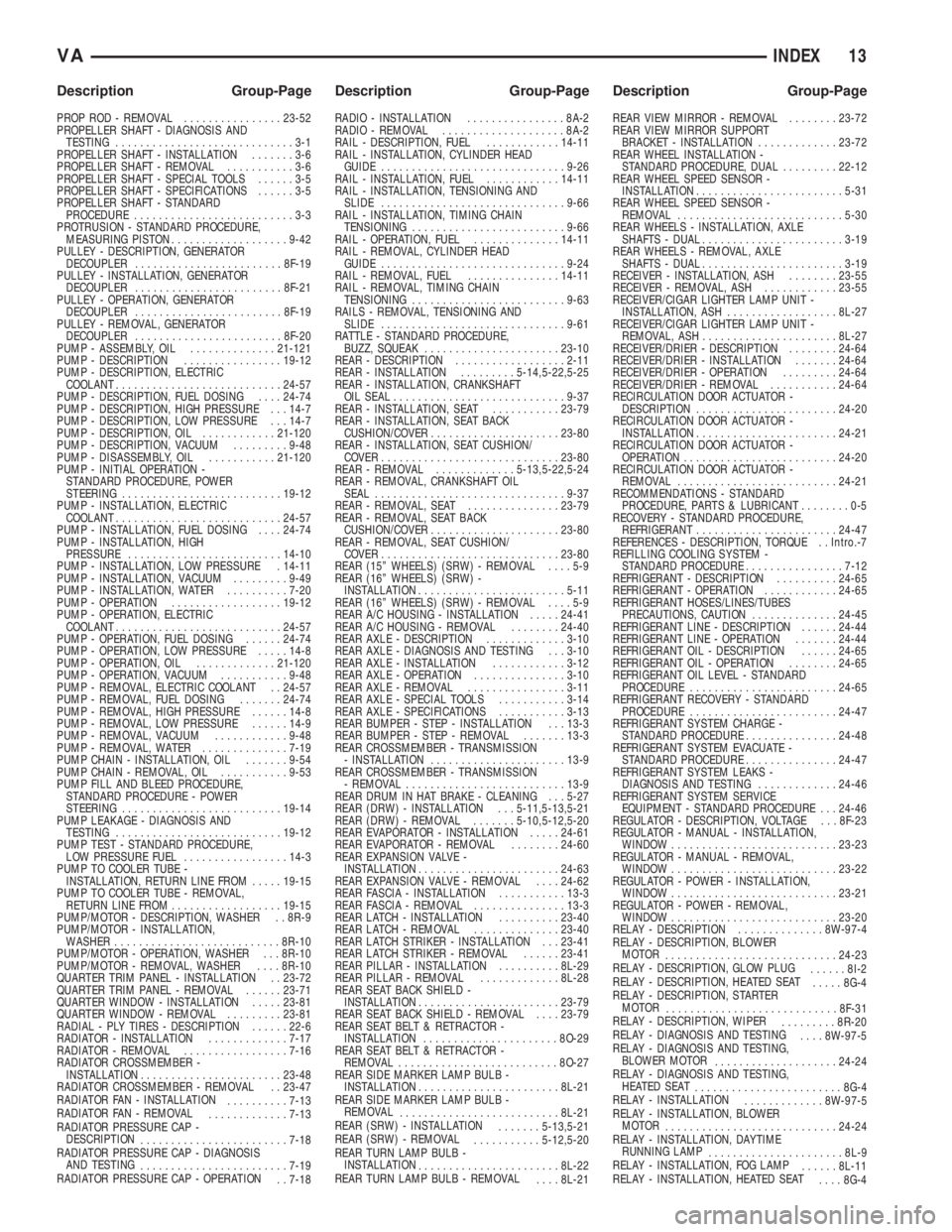
PROP ROD - REMOVAL................23-52
PROPELLER SHAFT - DIAGNOSIS AND
TESTING.............................3-1
PROPELLER SHAFT - INSTALLATION.......3-6
PROPELLER SHAFT - REMOVAL...........3-6
PROPELLER SHAFT - SPECIAL TOOLS......3-5
PROPELLER SHAFT - SPECIFICATIONS......3-5
PROPELLER SHAFT - STANDARD
PROCEDURE..........................3-3
PROTRUSION - STANDARD PROCEDURE,
MEASURING PISTON...................9-42
PULLEY - DESCRIPTION, GENERATOR
DECOUPLER........................8F-19
PULLEY - INSTALLATION, GENERATOR
DECOUPLER........................8F-21
PULLEY - OPERATION, GENERATOR
DECOUPLER........................8F-19
PULLEY - REMOVAL, GENERATOR
DECOUPLER........................8F-20
PUMP - ASSEMBLY, OIL..............21-121
PUMP - DESCRIPTION................19-12
PUMP - DESCRIPTION, ELECTRIC
COOLANT...........................24-57
PUMP - DESCRIPTION, FUEL DOSING....24-74
PUMP - DESCRIPTION, HIGH PRESSURE . . . 14-7
PUMP - DESCRIPTION, LOW PRESSURE . . . 14-7
PUMP - DESCRIPTION, OIL............21-120
PUMP - DESCRIPTION, VACUUM.........9-48
PUMP - DISASSEMBLY, OIL...........21-120
PUMP - INITIAL OPERATION -
STANDARD PROCEDURE, POWER
STEERING..........................19-12
PUMP - INSTALLATION, ELECTRIC
COOLANT...........................24-57
PUMP - INSTALLATION, FUEL DOSING....24-74
PUMP - INSTALLATION, HIGH
PRESSURE.........................14-10
PUMP - INSTALLATION, LOW PRESSURE . 14-11
PUMP - INSTALLATION, VACUUM.........9-49
PUMP - INSTALLATION, WATER..........7-20
PUMP - OPERATION..................19-12
PUMP - OPERATION, ELECTRIC
COOLANT...........................24-57
PUMP - OPERATION, FUEL DOSING......24-74
PUMP - OPERATION, LOW PRESSURE.....14-8
PUMP - OPERATION, OIL.............21-120
PUMP - OPERATION, VACUUM...........9-48
PUMP - REMOVAL, ELECTRIC COOLANT . . 24-57
PUMP - REMOVAL, FUEL DOSING.......24-74
PUMP - REMOVAL, HIGH PRESSURE......14-8
PUMP - REMOVAL, LOW PRESSURE......14-9
PUMP - REMOVAL, VACUUM............9-48
PUMP - REMOVAL, WATER..............7-19
PUMP CHAIN - INSTALLATION, OIL.......9-54
PUMP CHAIN - REMOVAL, OIL...........9-53
PUMP FILL AND BLEED PROCEDURE,
STANDARD PROCEDURE - POWER
STEERING..........................19-14
PUMP LEAKAGE - DIAGNOSIS AND
TESTING...........................19-12
PUMP TEST - STANDARD PROCEDURE,
LOW PRESSURE FUEL.................14-3
PUMP TO COOLER TUBE -
INSTALLATION, RETURN LINE FROM.....19-15
PUMP TO COOLER TUBE - REMOVAL,
RETURN LINE FROM..................19-15
PUMP/MOTOR - DESCRIPTION, WASHER . . 8R-9
PUMP/MOTOR - INSTALLATION,
WASHER...........................8R-10
PUMP/MOTOR - OPERATION, WASHER . . . 8R-10
PUMP/MOTOR - REMOVAL, WASHER....8R-10
QUARTER TRIM PANEL - INSTALLATION . . 23-72
QUARTER TRIM PANEL - REMOVAL......23-71
QUARTER WINDOW - INSTALLATION.....23-81
QUARTER WINDOW - REMOVAL.........23-81
RADIAL - PLY TIRES - DESCRIPTION......22-6
RADIATOR - INSTALLATION.............7-17
RADIATOR - REMOVAL.................7-16
RADIATOR CROSSMEMBER -
INSTALLATION.......................23-48
RADIATOR CROSSMEMBER - REMOVAL . . 23-47
RADIATOR FAN - INSTALLATION
..........7-13
RADIATOR FAN - REMOVAL
.............7-13
RADIATOR PRESSURE CAP -
DESCRIPTION
........................7-18
RADIATOR PRESSURE CAP - DIAGNOSIS
AND TESTING
........................7-19
RADIATOR PRESSURE CAP - OPERATION
. . 7-18RADIO - INSTALLATION................8A-2
RADIO - REMOVAL....................8A-2
RAIL - DESCRIPTION, FUEL............14-11
RAIL - INSTALLATION, CYLINDER HEAD
GUIDE..............................9-26
RAIL - INSTALLATION, FUEL............14-11
RAIL - INSTALLATION, TENSIONING AND
SLIDE..............................9-66
RAIL - INSTALLATION, TIMING CHAIN
TENSIONING.........................9-66
RAIL - OPERATION, FUEL..............14-11
RAIL - REMOVAL, CYLINDER HEAD
GUIDE..............................9-24
RAIL - REMOVAL, FUEL...............14-11
RAIL - REMOVAL, TIMING CHAIN
TENSIONING.........................9-63
RAILS - REMOVAL, TENSIONING AND
SLIDE..............................9-61
RATTLE - STANDARD PROCEDURE,
BUZZ, SQUEAK......................23-10
REAR - DESCRIPTION..................2-11
REAR - INSTALLATION.........5-14,5-22,5-25
REAR - INSTALLATION, CRANKSHAFT
OIL SEAL............................9-37
REAR - INSTALLATION, SEAT...........23-79
REAR - INSTALLATION, SEAT BACK
CUSHION/COVER.....................23-80
REAR - INSTALLATION, SEAT CUSHION/
COVER.............................23-80
REAR - REMOVAL.............5-13,5-22,5-24
REAR - REMOVAL, CRANKSHAFT OIL
SEAL...............................9-37
REAR - REMOVAL, SEAT...............23-79
REAR - REMOVAL, SEAT BACK
CUSHION/COVER.....................23-80
REAR - REMOVAL, SEAT CUSHION/
COVER.............................23-80
REAR (15º WHEELS) (SRW) - REMOVAL....5-9
REAR (16º WHEELS) (SRW) -
INSTALLATION........................5-11
REAR (16º WHEELS) (SRW) - REMOVAL....5-9
REAR A/C HOUSING - INSTALLATION.....24-41
REAR A/C HOUSING - REMOVAL........24-40
REAR AXLE - DESCRIPTION.............3-10
REAR AXLE - DIAGNOSIS AND TESTING . . . 3-10
REAR AXLE - INSTALLATION............3-12
REAR AXLE - OPERATION...............3-10
REAR AXLE - REMOVAL................3-11
REAR AXLE - SPECIAL TOOLS...........3-14
REAR AXLE - SPECIFICATIONS...........3-13
REAR BUMPER - STEP - INSTALLATION . . . 13-3
REAR BUMPER - STEP - REMOVAL.......13-3
REAR CROSSMEMBER - TRANSMISSION
- INSTALLATION......................13-9
REAR CROSSMEMBER - TRANSMISSION
- REMOVAL..........................13-9
REAR DRUM IN HAT BRAKE - CLEANING . . . 5-27
REAR (DRW) - INSTALLATION . . . 5-11,5-13,5-21
REAR (DRW) - REMOVAL.......5-10,5-12,5-20
REAR EVAPORATOR - INSTALLATION.....24-61
REAR EVAPORATOR - REMOVAL........24-60
REAR EXPANSION VALVE -
INSTALLATION.......................24-63
REAR EXPANSION VALVE - REMOVAL....24-62
REAR FASCIA - INSTALLATION...........13-3
REAR FASCIA - REMOVAL...............13-3
REAR LATCH - INSTALLATION..........23-40
REAR LATCH - REMOVAL..............23-40
REAR LATCH STRIKER - INSTALLATION . . . 23-41
REAR LATCH STRIKER - REMOVAL......23-41
REAR PILLAR - INSTALLATION..........8L-29
REAR PILLAR - REMOVAL.............8L-28
REAR SEAT BACK SHIELD -
INSTALLATION.......................23-79
REAR SEAT BACK SHIELD - REMOVAL....23-79
REAR SEAT BELT & RETRACTOR -
INSTALLATION......................8O-29
REAR SEAT BELT & RETRACTOR -
REMOVAL..........................8O-27
REAR SIDE MARKER LAMP BULB -
INSTALLATION.......................8L-21
REAR SIDE MARKER LAMP BULB -
REMOVAL
..........................8L-21
REAR (SRW) - INSTALLATION
.......5-13,5-21
REAR (SRW) - REMOVAL
...........5-12,5-20
REAR TURN LAMP BULB -
INSTALLATION
.......................8L-22
REAR TURN LAMP BULB - REMOVAL
....8L-21REAR VIEW MIRROR - REMOVAL........23-72
REAR VIEW MIRROR SUPPORT
BRACKET - INSTALLATION.............23-72
REAR WHEEL INSTALLATION -
STANDARD PROCEDURE, DUAL.........22-12
REAR WHEEL SPEED SENSOR -
INSTALLATION........................5-31
REAR WHEEL SPEED SENSOR -
REMOVAL...........................5-30
REAR WHEELS - INSTALLATION, AXLE
SHAFTS - DUAL.......................3-19
REAR WHEELS - REMOVAL, AXLE
SHAFTS - DUAL.......................3-19
RECEIVER - INSTALLATION, ASH........23-55
RECEIVER - REMOVAL, ASH............23-55
RECEIVER/CIGAR LIGHTER LAMP UNIT -
INSTALLATION, ASH..................8L-27
RECEIVER/CIGAR LIGHTER LAMP UNIT -
REMOVAL, ASH......................8L-27
RECEIVER/DRIER - DESCRIPTION........24-64
RECEIVER/DRIER - INSTALLATION.......24-64
RECEIVER/DRIER - OPERATION.........24-64
RECEIVER/DRIER - REMOVAL...........24-64
RECIRCULATION DOOR ACTUATOR -
DESCRIPTION.......................24-20
RECIRCULATION DOOR ACTUATOR -
INSTALLATION.......................24-21
RECIRCULATION DOOR ACTUATOR -
OPERATION.........................24-20
RECIRCULATION DOOR ACTUATOR -
REMOVAL..........................24-21
RECOMMENDATIONS - STANDARD
PROCEDURE, PARTS & LUBRICANT........0-5
RECOVERY - STANDARD PROCEDURE,
REFRIGERANT.......................24-47
REFERENCES - DESCRIPTION, TORQUE . . Intro.-7
REFILLING COOLING SYSTEM -
STANDARD PROCEDURE................7-12
REFRIGERANT - DESCRIPTION..........24-65
REFRIGERANT - OPERATION............24-65
REFRIGERANT HOSES/LINES/TUBES
PRECAUTIONS, CAUTION..............24-45
REFRIGERANT LINE - DESCRIPTION......24-44
REFRIGERANT LINE - OPERATION.......24-44
REFRIGERANT OIL - DESCRIPTION......24-65
REFRIGERANT OIL - OPERATION........24-65
REFRIGERANT OIL LEVEL - STANDARD
PROCEDURE........................24-65
REFRIGERANT RECOVERY - STANDARD
PROCEDURE........................24-47
REFRIGERANT SYSTEM CHARGE -
STANDARD PROCEDURE...............24-48
REFRIGERANT SYSTEM EVACUATE -
STANDARD PROCEDURE...............24-47
REFRIGERANT SYSTEM LEAKS -
DIAGNOSIS AND TESTING.............24-46
REFRIGERANT SYSTEM SERVICE
EQUIPMENT - STANDARD PROCEDURE . . . 24-46
REGULATOR - DESCRIPTION, VOLTAGE . . . 8F-23
REGULATOR - MANUAL - INSTALLATION,
WINDOW...........................23-23
REGULATOR - MANUAL - REMOVAL,
WINDOW...........................23-22
REGULATOR - POWER - INSTALLATION,
WINDOW...........................23-21
REGULATOR - POWER - REMOVAL,
WINDOW...........................23-20
RELAY - DESCRIPTION..............8W-97-4
RELAY - DESCRIPTION, BLOWER
MOTOR
............................24-23
RELAY - DESCRIPTION, GLOW PLUG
......8I-2
RELAY - DESCRIPTION, HEATED SEAT
.....8G-4
RELAY - DESCRIPTION, STARTER
MOTOR
............................8F-31
RELAY - DESCRIPTION, WIPER
.........8R-20
RELAY - DIAGNOSIS AND TESTING
....8W-97-5
RELAY - DIAGNOSIS AND TESTING,
BLOWER MOTOR
....................24-24
RELAY - DIAGNOSIS AND TESTING,
HEATED SEAT
........................8G-4
RELAY - INSTALLATION
.............8W-97-5
RELAY - INSTALLATION, BLOWER
MOTOR
............................24-24
RELAY - INSTALLATION, DAYTIME
RUNNING LAMP
......................8L-9
RELAY - INSTALLATION, FOG LAMP
......8L-11
RELAY - INSTALLATION, HEATED SEAT
....8G-4
VAINDEX 13
Description Group-Page Description Group-Page Description Group-Page
Page 1227 of 1232
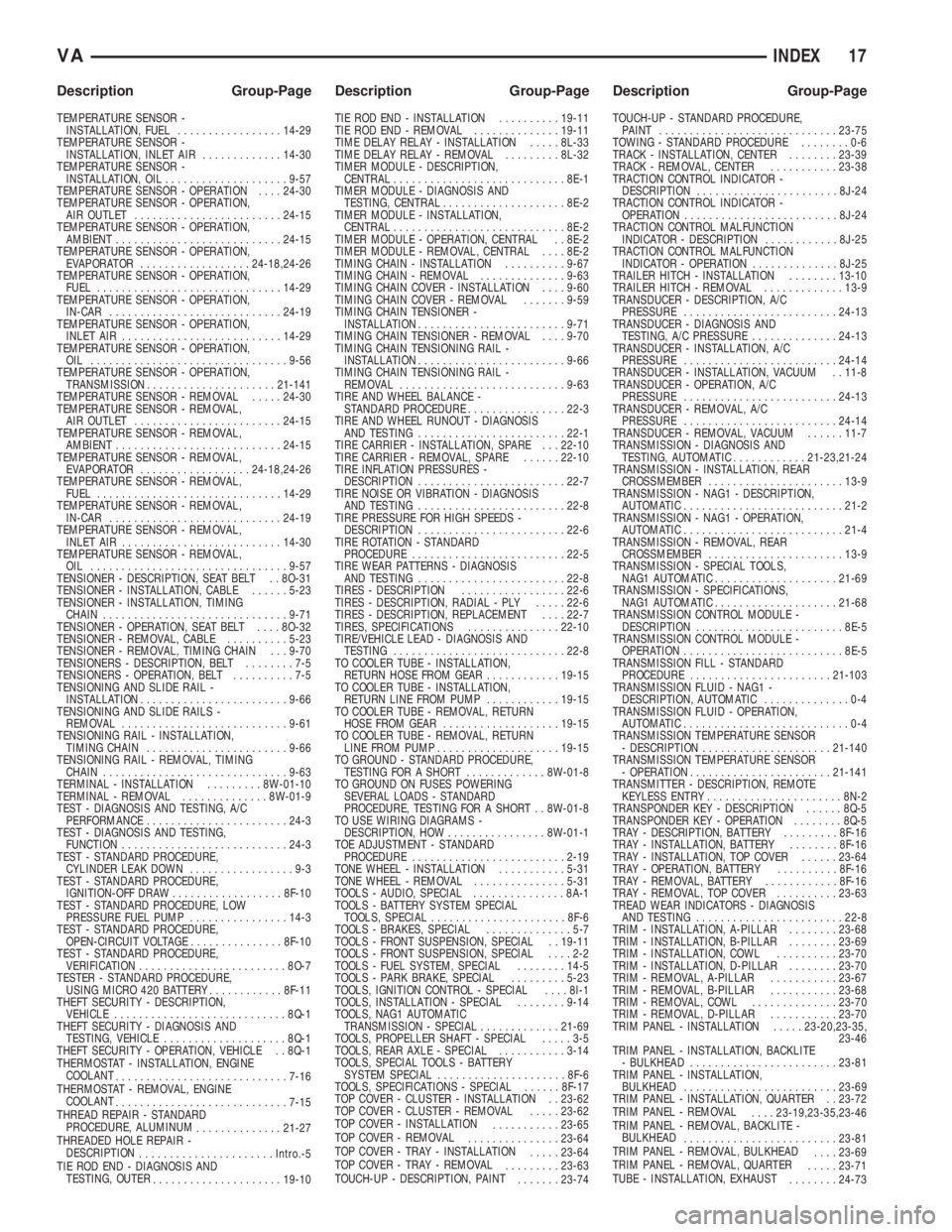
TEMPERATURE SENSOR -
INSTALLATION, FUEL.................14-29
TEMPERATURE SENSOR -
INSTALLATION, INLET AIR.............14-30
TEMPERATURE SENSOR -
INSTALLATION, OIL....................9-57
TEMPERATURE SENSOR - OPERATION....24-30
TEMPERATURE SENSOR - OPERATION,
AIR OUTLET........................24-15
TEMPERATURE SENSOR - OPERATION,
AMBIENT...........................24-15
TEMPERATURE SENSOR - OPERATION,
EVAPORATOR..................24-18,24-26
TEMPERATURE SENSOR - OPERATION,
FUEL..............................14-29
TEMPERATURE SENSOR - OPERATION,
IN-CAR............................24-19
TEMPERATURE SENSOR - OPERATION,
INLET AIR..........................14-29
TEMPERATURE SENSOR - OPERATION,
OIL ................................9-56
TEMPERATURE SENSOR - OPERATION,
TRANSMISSION.....................21-141
TEMPERATURE SENSOR - REMOVAL.....24-30
TEMPERATURE SENSOR - REMOVAL,
AIR OUTLET........................24-15
TEMPERATURE SENSOR - REMOVAL,
AMBIENT...........................24-15
TEMPERATURE SENSOR - REMOVAL,
EVAPORATOR..................24-18,24-26
TEMPERATURE SENSOR - REMOVAL,
FUEL..............................14-29
TEMPERATURE SENSOR - REMOVAL,
IN-CAR............................24-19
TEMPERATURE SENSOR - REMOVAL,
INLET AIR..........................14-30
TEMPERATURE SENSOR - REMOVAL,
OIL ................................9-57
TENSIONER - DESCRIPTION, SEAT BELT . . 8O-31
TENSIONER - INSTALLATION, CABLE......5-23
TENSIONER - INSTALLATION, TIMING
CHAIN..............................9-71
TENSIONER - OPERATION, SEAT BELT....8O-32
TENSIONER - REMOVAL, CABLE..........5-23
TENSIONER - REMOVAL, TIMING CHAIN . . . 9-70
TENSIONERS - DESCRIPTION, BELT........7-5
TENSIONERS - OPERATION, BELT..........7-5
TENSIONING AND SLIDE RAIL -
INSTALLATION........................9-66
TENSIONING AND SLIDE RAILS -
REMOVAL...........................9-61
TENSIONING RAIL - INSTALLATION,
TIMING CHAIN.......................9-66
TENSIONING RAIL - REMOVAL, TIMING
CHAIN..............................9-63
TERMINAL - INSTALLATION.........8W-01-10
TERMINAL - REMOVAL..............8W-01-9
TEST - DIAGNOSIS AND TESTING, A/C
PERFORMANCE.......................24-3
TEST - DIAGNOSIS AND TESTING,
FUNCTION...........................24-3
TEST - STANDARD PROCEDURE,
CYLINDER LEAK DOWN.................9-3
TEST - STANDARD PROCEDURE,
IGNITION-OFF DRAW..................8F-10
TEST - STANDARD PROCEDURE, LOW
PRESSURE FUEL PUMP................14-3
TEST - STANDARD PROCEDURE,
OPEN-CIRCUIT VOLTAGE...............8F-10
TEST - STANDARD PROCEDURE,
VERIFICATION........................8O-7
TESTER - STANDARD PROCEDURE,
USING MICRO 420 BATTERY............8F-11
THEFT SECURITY - DESCRIPTION,
VEHICLE............................8Q-1
THEFT SECURITY - DIAGNOSIS AND
TESTING, VEHICLE....................8Q-1
THEFT SECURITY - OPERATION, VEHICLE . . 8Q-1
THERMOSTAT - INSTALLATION, ENGINE
COOLANT
............................7-16
THERMOSTAT - REMOVAL, ENGINE
COOLANT
............................7-15
THREAD REPAIR - STANDARD
PROCEDURE, ALUMINUM
..............21-27
THREADED HOLE REPAIR -
DESCRIPTION
......................Intro.-5
TIE ROD END - DIAGNOSIS AND
TESTING, OUTER
.....................19-10TIE ROD END - INSTALLATION..........19-11
TIE ROD END - REMOVAL..............19-11
TIME DELAY RELAY - INSTALLATION.....8L-33
TIME DELAY RELAY - REMOVAL.........8L-32
TIMER MODULE - DESCRIPTION,
CENTRAL............................8E-1
TIMER MODULE - DIAGNOSIS AND
TESTING, CENTRAL....................8E-2
TIMER MODULE - INSTALLATION,
CENTRAL............................8E-2
TIMER MODULE - OPERATION, CENTRAL . . 8E-2
TIMER MODULE - REMOVAL, CENTRAL....8E-2
TIMING CHAIN - INSTALLATION..........9-67
TIMING CHAIN - REMOVAL..............9-63
TIMING CHAIN COVER - INSTALLATION....9-60
TIMING CHAIN COVER - REMOVAL.......9-59
TIMING CHAIN TENSIONER -
INSTALLATION........................9-71
TIMING CHAIN TENSIONER - REMOVAL....9-70
TIMING CHAIN TENSIONING RAIL -
INSTALLATION........................9-66
TIMING CHAIN TENSIONING RAIL -
REMOVAL...........................9-63
TIRE AND WHEEL BALANCE -
STANDARD PROCEDURE................22-3
TIRE AND WHEEL RUNOUT - DIAGNOSIS
AND TESTING........................22-1
TIRE CARRIER - INSTALLATION, SPARE . . . 22-10
TIRE CARRIER - REMOVAL, SPARE......22-10
TIRE INFLATION PRESSURES -
DESCRIPTION........................22-7
TIRE NOISE OR VIBRATION - DIAGNOSIS
AND TESTING........................22-8
TIRE PRESSURE FOR HIGH SPEEDS -
DESCRIPTION........................22-6
TIRE ROTATION - STANDARD
PROCEDURE.........................22-5
TIRE WEAR PATTERNS - DIAGNOSIS
AND TESTING........................22-8
TIRES - DESCRIPTION.................22-6
TIRES - DESCRIPTION, RADIAL - PLY.....22-6
TIRES - DESCRIPTION, REPLACEMENT....22-7
TIRES, SPECIFICATIONS...............22-10
TIRE/VEHICLE LEAD - DIAGNOSIS AND
TESTING............................22-8
TO COOLER TUBE - INSTALLATION,
RETURN HOSE FROM GEAR............19-15
TO COOLER TUBE - INSTALLATION,
RETURN LINE FROM PUMP............19-15
TO COOLER TUBE - REMOVAL, RETURN
HOSE FROM GEAR...................19-15
TO COOLER TUBE - REMOVAL, RETURN
LINE FROM PUMP....................19-15
TO GROUND - STANDARD PROCEDURE,
TESTING FOR A SHORT.............8W-01-8
TO GROUND ON FUSES POWERING
SEVERAL LOADS - STANDARD
PROCEDURE, TESTING FOR A SHORT . . 8W-01-8
TO USE WIRING DIAGRAMS -
DESCRIPTION, HOW................8W-01-1
TOE ADJUSTMENT - STANDARD
PROCEDURE.........................2-19
TONE WHEEL - INSTALLATION...........5-31
TONE WHEEL - REMOVAL...............5-31
TOOLS - AUDIO, SPECIAL...............8A-1
TOOLS - BATTERY SYSTEM SPECIAL
TOOLS, SPECIAL......................8F-6
TOOLS - BRAKES, SPECIAL..............5-7
TOOLS - FRONT SUSPENSION, SPECIAL . . 19-11
TOOLS - FRONT SUSPENSION, SPECIAL....2-2
TOOLS - FUEL SYSTEM, SPECIAL........14-5
TOOLS - PARK BRAKE, SPECIAL.........5-23
TOOLS, IGNITION CONTROL - SPECIAL....8I-1
TOOLS, INSTALLATION - SPECIAL........9-14
TOOLS, NAG1 AUTOMATIC
TRANSMISSION - SPECIAL.............21-69
TOOLS, PROPELLER SHAFT - SPECIAL.....3-5
TOOLS, REAR AXLE - SPECIAL...........3-14
TOOLS, SPECIAL TOOLS - BATTERY
SYSTEM SPECIAL.....................8F-6
TOOLS, SPECIFICATIONS - SPECIAL......8F-17
TOP COVER - CLUSTER - INSTALLATION . . 23-62
TOP COVER - CLUSTER - REMOVAL.....23-62
TOP COVER - INSTALLATION
...........23-65
TOP COVER - REMOVAL
...............23-64
TOP COVER - TRAY - INSTALLATION
.....23-64
TOP COVER - TRAY - REMOVAL
.........23-63
TOUCH-UP - DESCRIPTION, PAINT
.......23-74TOUCH-UP - STANDARD PROCEDURE,
PAINT.............................23-75
TOWING - STANDARD PROCEDURE........0-6
TRACK - INSTALLATION, CENTER........23-39
TRACK - REMOVAL, CENTER...........23-38
TRACTION CONTROL INDICATOR -
DESCRIPTION.......................8J-24
TRACTION CONTROL INDICATOR -
OPERATION.........................8J-24
TRACTION CONTROL MALFUNCTION
INDICATOR - DESCRIPTION............8J-25
TRACTION CONTROL MALFUNCTION
INDICATOR - OPERATION..............8J-25
TRAILER HITCH - INSTALLATION........13-10
TRAILER HITCH - REMOVAL.............13-9
TRANSDUCER - DESCRIPTION, A/C
PRESSURE.........................24-13
TRANSDUCER - DIAGNOSIS AND
TESTING, A/C PRESSURE..............24-13
TRANSDUCER - INSTALLATION, A/C
PRESSURE.........................24-14
TRANSDUCER - INSTALLATION, VACUUM . . 11-8
TRANSDUCER - OPERATION, A/C
PRESSURE.........................24-13
TRANSDUCER - REMOVAL, A/C
PRESSURE.........................24-14
TRANSDUCER - REMOVAL, VACUUM......11-7
TRANSMISSION - DIAGNOSIS AND
TESTING, AUTOMATIC............21-23,21-24
TRANSMISSION - INSTALLATION, REAR
CROSSMEMBER......................13-9
TRANSMISSION - NAG1 - DESCRIPTION,
AUTOMATIC..........................21-2
TRANSMISSION - NAG1 - OPERATION,
AUTOMATIC..........................21-4
TRANSMISSION - REMOVAL, REAR
CROSSMEMBER......................13-9
TRANSMISSION - SPECIAL TOOLS,
NAG1 AUTOMATIC....................21-69
TRANSMISSION - SPECIFICATIONS,
NAG1 AUTOMATIC....................21-68
TRANSMISSION CONTROL MODULE -
DESCRIPTION........................8E-5
TRANSMISSION CONTROL MODULE -
OPERATION..........................8E-5
TRANSMISSION FILL - STANDARD
PROCEDURE.......................21-103
TRANSMISSION FLUID - NAG1 -
DESCRIPTION, AUTOMATIC..............0-4
TRANSMISSION FLUID - OPERATION,
AUTOMATIC...........................0-4
TRANSMISSION TEMPERATURE SENSOR
- DESCRIPTION.....................21-140
TRANSMISSION TEMPERATURE SENSOR
- OPERATION.......................21-141
TRANSMITTER - DESCRIPTION, REMOTE
KEYLESS ENTRY......................8N-2
TRANSPONDER KEY - DESCRIPTION......8Q-5
TRANSPONDER KEY - OPERATION........8Q-5
TRAY - DESCRIPTION, BATTERY.........8F-16
TRAY - INSTALLATION, BATTERY........8F-16
TRAY - INSTALLATION, TOP COVER......23-64
TRAY - OPERATION, BATTERY..........8F-16
TRAY - REMOVAL, BATTERY............8F-16
TRAY - REMOVAL, TOP COVER..........23-63
TREAD WEAR INDICATORS - DIAGNOSIS
AND TESTING........................22-8
TRIM - INSTALLATION, A-PILLAR........23-68
TRIM - INSTALLATION, B-PILLAR........23-69
TRIM - INSTALLATION, COWL..........23-70
TRIM - INSTALLATION, D-PILLAR........23-70
TRIM - REMOVAL, A-PILLAR...........23-67
TRIM - REMOVAL, B-PILLAR...........23-68
TRIM - REMOVAL, COWL..............23-70
TRIM - REMOVAL, D-PILLAR...........23-70
TRIM PANEL - INSTALLATION.....23-20,23-35,
23-46
TRIM PANEL - INSTALLATION, BACKLITE
- BULKHEAD........................23-81
TRIM PANEL - INSTALLATION,
BULKHEAD.........................23-69
TRIM PANEL - INSTALLATION, QUARTER . . 23-72
TRIM PANEL - REMOVAL
....23-19,23-35,23-46
TRIM PANEL - REMOVAL, BACKLITE -
BULKHEAD
.........................23-81
TRIM PANEL - REMOVAL, BULKHEAD
....23-69
TRIM PANEL - REMOVAL, QUARTER
.....23-71
TUBE - INSTALLATION, EXHAUST
........24-73
VAINDEX 17
Description Group-Page Description Group-Page Description Group-Page