2005 MERCEDES-BENZ SPRINTER timing belt
[x] Cancel search: timing beltPage 798 of 1232
(6) Remove the oil filter to allow the oil to flow off
into the oil pan.
(7) Remove the radiator assembly (Refer to 7 -
COOLING/ENGINE/RADIATOR - REMOVAL).
(8) Remove engine cover (Refer to 9 - ENGINE -
REMOVAL).
(9) Remove front cover at cylinder head (Refer to 9
- ENGINE/CYLINDER HEAD - REMOVAL).
(10) Remove accessory drive belt.
(11) Remove the high pressure fuel pump (Refer to
14 - FUEL SYSTEM/FUEL DELIVERY/FUEL PUMP
- REMOVAL).
(12) Remove water pump (Refer to 7 - COOLING/
ENGINE/WATER PUMP - REMOVAL).
(13) Remove accessory drive belt pulley and vibra-
tion damper (Refer to 9 - ENGINE/ENGINE BLOCK/
VIBRATION DAMPER - REMOVAL).
(14) Remove the power steering pump.
NOTE: NO NOT open the air conditioning system.
(15) Unplug AC compressor electrical connector
and unbolt AC compressor. Relocate in lower engine
compartmentwith outopening the system.
(16) Remove the generator with wiring attached
and relocate somewhere in the engine compartment.
(17) Install engine support fixture.
(18) Remove the oil pan.
(19) Detach the coolant hose to oil-water heat
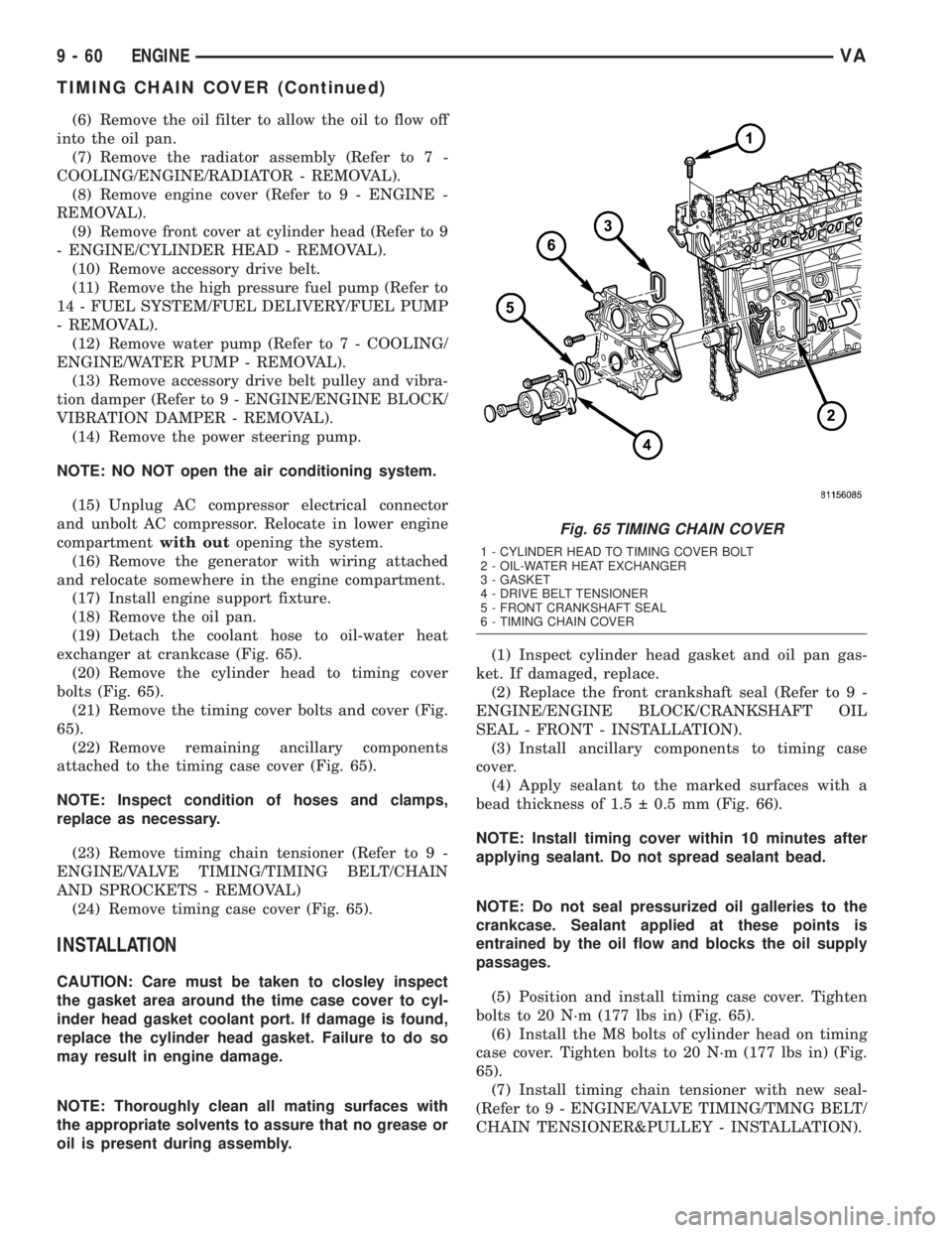
exchanger at crankcase (Fig. 65).
(20) Remove the cylinder head to timing cover
bolts (Fig. 65).
(21) Remove the timing cover bolts and cover (Fig.
65).
(22) Remove remaining ancillary components
attached to the timing case cover (Fig. 65).
NOTE: Inspect condition of hoses and clamps,
replace as necessary.
(23) Remove timing chain tensioner (Refer to 9 -
ENGINE/VALVE TIMING/TIMING BELT/CHAIN
AND SPROCKETS - REMOVAL)
(24) Remove timing case cover (Fig. 65).
INSTALLATION
CAUTION: Care must be taken to closley inspect
the gasket area around the time case cover to cyl-
inder head gasket coolant port. If damage is found,
replace the cylinder head gasket. Failure to do so
may result in engine damage.
NOTE: Thoroughly clean all mating surfaces with
the appropriate solvents to assure that no grease or
oil is present during assembly.(1) Inspect cylinder head gasket and oil pan gas-
ket. If damaged, replace.
(2) Replace the front crankshaft seal (Refer to 9 -
ENGINE/ENGINE BLOCK/CRANKSHAFT OIL
SEAL - FRONT - INSTALLATION).
(3) Install ancillary components to timing case
cover.
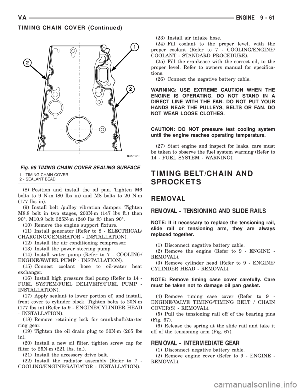
(4) Apply sealant to the marked surfaces with a
bead thickness of 1.5 0.5 mm (Fig. 66).
NOTE: Install timing cover within 10 minutes after
applying sealant. Do not spread sealant bead.
NOTE: Do not seal pressurized oil galleries to the
crankcase. Sealant applied at these points is
entrained by the oil flow and blocks the oil supply
passages.
(5) Position and install timing case cover. Tighten
bolts to 20 N´m (177 lbs in) (Fig. 65).
(6) Install the M8 bolts of cylinder head on timing
case cover. Tighten bolts to 20 N´m (177 lbs in) (Fig.
65).
(7) Install timing chain tensioner with new seal-
(Refer to 9 - ENGINE/VALVE TIMING/TMNG BELT/
CHAIN TENSIONER&PULLEY - INSTALLATION).
Fig. 65 TIMING CHAIN COVER
1 - CYLINDER HEAD TO TIMING COVER BOLT
2 - OIL-WATER HEAT EXCHANGER
3 - GASKET
4 - DRIVE BELT TENSIONER
5 - FRONT CRANKSHAFT SEAL
6 - TIMING CHAIN COVER
9 - 60 ENGINEVA
TIMING CHAIN COVER (Continued)
Page 799 of 1232
(8) Position and install the oil pan. Tighten M6
bolts to 9 N´m (80 lbs in) and M8 bolts to 20 N´m
(177 lbs in).
(9) Install belt /pulley vibration damper. Tighten
M8.8 bolt in two stages, 200N´m (147 lbs ft.) then
90É, M10.9 bolt 325N´m (240 lbs ft) then 90É.
(10) Remove the engine support fixture.
(11) Install generator (Refer to 8 - ELECTRICAL/
CHARGING/GENERATOR - INSTALLATION).
(12) Install the air conditioning compressor.
(13) Install the power steering pump.
(14) Install water pump (Refer to 7 - COOLING/
ENGINE/WATER PUMP - INSTALLATION).
(15) Connect coolant hose to oil-water heat
exchanger.
(16) Install high pressure fuel pump (Refer to 14 -
FUEL SYSTEM/FUEL DELIVERY/FUEL PUMP -
INSTALLATION).
(17) Apply sealant to lower portion of, and install,
front cover to cylinder block. Tighten bolts to 20N´m
(177 lbs in) (Refer to 9 - ENGINE/CYLINDER HEAD
- INSTALLATION).
(18) Remove retaining lock for crankshaft/starter
ring gear.
(19) Tighten the oil drain plug to 30N´m (265 lbs
in).
(20) Install a new oil filter. tighten screw cap for
filter to 25N´m (221 lbs. in.).
(21) Install the accessory drive belt.
(22) Install the radiator assembly (Refer to 7 -
COOLING/ENGINE/RADIATOR - INSTALLATION).(23) Install air intake hose.
(24) Fill coolant to the proper level, with the
proper coolant (Refer to 7 - COOLING/ENGINE/
COOLANT - STANDARD PROCEDURE).
(25) Fill the crankcase with the correct oil, to the
proper level. Refer to owners manual for specifica-
tions.
(26) Connect the negative battery cable.
WARNING: USE EXTREME CAUTION WHEN THE
ENGINE IS OPERATING. DO NOT STAND IN A
DIRECT LINE WITH THE FAN. DO NOT PUT YOUR
HANDS NEAR THE PULLEYS, BELTS OR FAN. DO
NOT WEAR LOOSE CLOTHES.
CAUTION: DO NOT pressure test cooling system
until the engine reaches operating temperature.
(27) Start engine and inspect for leaks. care must
be taken to observe the fuel system warning (Refer to
14 - FUEL SYSTEM - WARNING).
TIMING BELT/CHAIN AND
SPROCKETS
REMOVAL
REMOVAL - TENSIONING AND SLIDE RAILS
NOTE: If it necessary to replace the tensioning rail,
slide rail or tensioning arm, they are always
replaced together.
(1) Disconnect negative battery cable.
(2) Remove the engine (Refer to 9 - ENGINE -
REMOVAL).
(3) Remove cylinder head (Refer to 9 - ENGINE/
CYLINDER HEAD - REMOVAL).
NOTE: Remove timing case cover carefully. Care
must be taken not to damage oil pan gasket.
(4) Remove timing case cover (Refer to 9 -
ENGINE/VALVE TIMING/TIMING BELT / CHAIN
COVER(S) - REMOVAL).
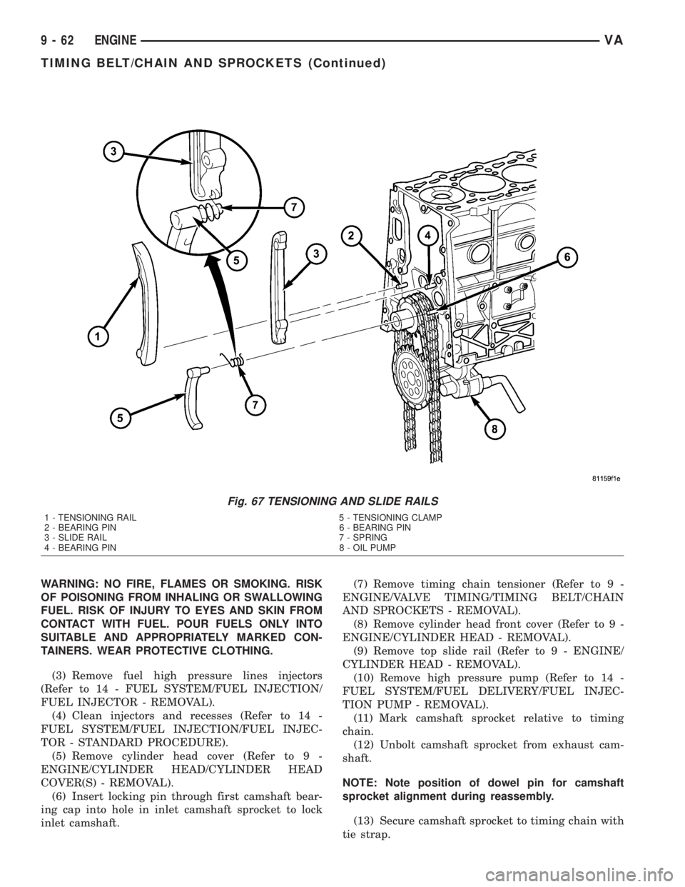
(5) Pull the tensioning rail off of the bearing pins
(Fig. 67).
(6) Release the spring at the slide rail and take it
off of the tensioning arm (Fig. 67).
REMOVAL - INTERMEDIATE GEAR
(1) Disconnect negative battery cable.
(2) Remove engine cover (Refer to 9 - ENGINE -
REMOVAL).
Fig. 66 TIMING CHAIN COVER SEALING SURFACE
1 - TIMING CHAIN COVER
2 - SEALANT BEAD
VAENGINE 9 - 61
TIMING CHAIN COVER (Continued)
Page 800 of 1232
WARNING: NO FIRE, FLAMES OR SMOKING. RISK
OF POISONING FROM INHALING OR SWALLOWING
FUEL. RISK OF INJURY TO EYES AND SKIN FROM
CONTACT WITH FUEL. POUR FUELS ONLY INTO
SUITABLE AND APPROPRIATELY MARKED CON-
TAINERS. WEAR PROTECTIVE CLOTHING.
(3) Remove fuel high pressure lines injectors
(Refer to 14 - FUEL SYSTEM/FUEL INJECTION/
FUEL INJECTOR - REMOVAL).
(4) Clean injectors and recesses (Refer to 14 -
FUEL SYSTEM/FUEL INJECTION/FUEL INJEC-
TOR - STANDARD PROCEDURE).
(5) Remove cylinder head cover (Refer to 9 -
ENGINE/CYLINDER HEAD/CYLINDER HEAD
COVER(S) - REMOVAL).
(6) Insert locking pin through first camshaft bear-
ing cap into hole in inlet camshaft sprocket to lock
inlet camshaft.(7) Remove timing chain tensioner (Refer to 9 -
ENGINE/VALVE TIMING/TIMING BELT/CHAIN
AND SPROCKETS - REMOVAL).
(8) Remove cylinder head front cover (Refer to 9 -
ENGINE/CYLINDER HEAD - REMOVAL).
(9) Remove top slide rail (Refer to 9 - ENGINE/
CYLINDER HEAD - REMOVAL).
(10) Remove high pressure pump (Refer to 14 -
FUEL SYSTEM/FUEL DELIVERY/FUEL INJEC-
TION PUMP - REMOVAL).
(11) Mark camshaft sprocket relative to timing
chain.
(12) Unbolt camshaft sprocket from exhaust cam-
shaft.
NOTE: Note position of dowel pin for camshaft
sprocket alignment during reassembly.
(13) Secure camshaft sprocket to timing chain with
tie strap.
Fig. 67 TENSIONING AND SLIDE RAILS
1 - TENSIONING RAIL 5 - TENSIONING CLAMP
2 - BEARING PIN 6 - BEARING PIN
3 - SLIDE RAIL 7 - SPRING
4 - BEARING PIN 8 - OIL PUMP
9 - 62 ENGINEVA
TIMING BELT/CHAIN AND SPROCKETS (Continued)
Page 801 of 1232
(14) Remove camshaft sprocket.
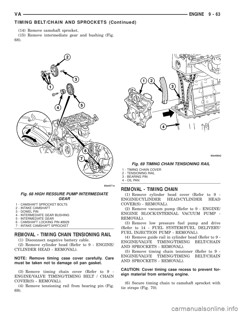
(15) Remove intermediate gear and bushing (Fig.
68).
REMOVAL - TIMING CHAIN TENSIONING RAIL
(1) Disconnect negative battery cable.
(2) Remove cylinder head (Refer to 9 - ENGINE/
CYLINDER HEAD - REMOVAL).
NOTE: Remove timing case cover carefully. Care
must be taken not to damage oil pan gasket.
(3) Remove timing chain cover (Refer to 9 -
ENGINE/VALVE TIMING/TIMING BELT / CHAIN
COVER(S) - REMOVAL).
(4) Remove tensioning rail from bearing pin (Fig.
69).
REMOVAL - TIMING CHAIN
(1) Remove cylinder head cover (Refer to 9 -
ENGINE/CYLINDER HEAD/CYLINDER HEAD
COVER(S) - REMOVAL).
(2) Remove vacuum pump (Refer to 9 - ENGINE/
ENGINE BLOCK/INTERNAL VACUUM PUMP -
REMOVAL).
(3) Remove low pressure fuel pump and drive
(Refer to 14 - FUEL SYSTEM/FUEL DELIVERY/
FUEL INJECTION PUMP - REMOVAL).
(4) Remove guide rail in cylinder head (Refer to 9 -
ENGINE/VALVE TIMING/TIMING BELT/CHAIN
AND SPROCKETS - REMOVAL).
(5) Remove timing chain tensioner (Refer to 9 -
ENGINE/VALVE TIMING/TIMING BELT/CHAIN
AND SPROCKETS - REMOVAL).
CAUTION: Cover timing case recess to prevent for-
eign material from entering engine.
(6) Secure timing chain to camshaft sprocket with
tie straps (Fig. 70).Fig. 68 HIGH RESSURE PUMP INTERMEDIATE
GEAR
1 - CAMSHAFT SPROCKET BOLTS
2 - INTAKE CAMSHAFT
3 - DOWEL PIN
4 - INTERMEDIATE GEAR BUSHING
5 - INTERMEDIATE GEAR
6 - CAMSHAFT LOCKING PIN #8929
7 - INTAKE CAMSHAFT SPROCKET
Fig. 69 TIMING CHAIN TENSIONING RAIL
1 - TIMING CHAIN COVER
2 - TENSIONING RAIL
3 - BEARING PIN
4 - OIL PAN
VAENGINE 9 - 63
TIMING BELT/CHAIN AND SPROCKETS (Continued)
Page 802 of 1232
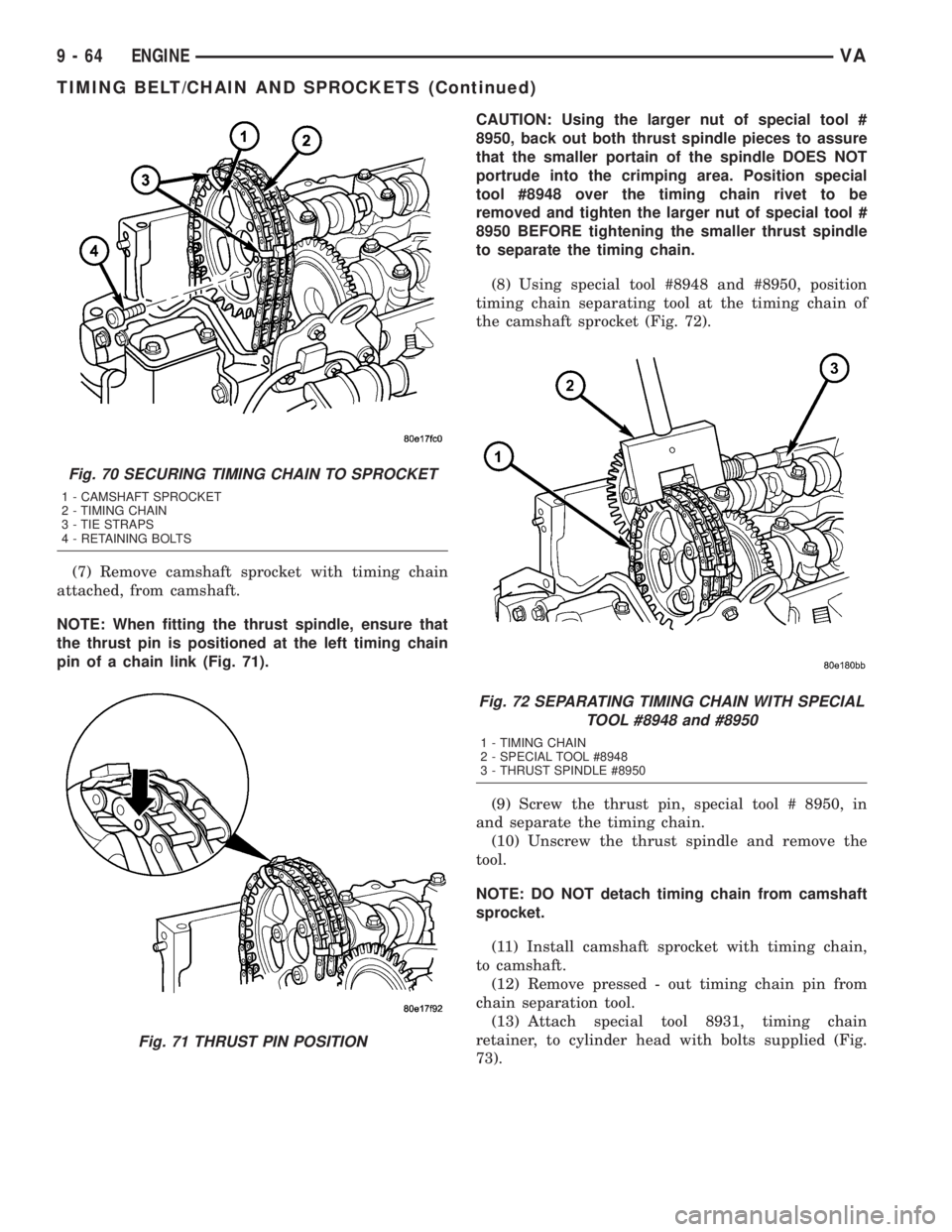
(7) Remove camshaft sprocket with timing chain
attached, from camshaft.
NOTE: When fitting the thrust spindle, ensure that
the thrust pin is positioned at the left timing chain
pin of a chain link (Fig. 71).CAUTION: Using the larger nut of special tool #
8950, back out both thrust spindle pieces to assure
that the smaller portain of the spindle DOES NOT
portrude into the crimping area. Position special
tool #8948 over the timing chain rivet to be
removed and tighten the larger nut of special tool #
8950 BEFORE tightening the smaller thrust spindle
to separate the timing chain.
(8) Using special tool #8948 and #8950, position
timing chain separating tool at the timing chain of
the camshaft sprocket (Fig. 72).
(9) Screw the thrust pin, special tool # 8950, in
and separate the timing chain.
(10) Unscrew the thrust spindle and remove the
tool.
NOTE: DO NOT detach timing chain from camshaft
sprocket.
(11) Install camshaft sprocket with timing chain,
to camshaft.
(12) Remove pressed - out timing chain pin from
chain separation tool.
(13) Attach special tool 8931, timing chain
retainer, to cylinder head with bolts supplied (Fig.
73).
Fig. 70 SECURING TIMING CHAIN TO SPROCKET
1 - CAMSHAFT SPROCKET
2 - TIMING CHAIN
3 - TIE STRAPS
4 - RETAINING BOLTS
Fig. 71 THRUST PIN POSITION
Fig. 72 SEPARATING TIMING CHAIN WITH SPECIAL
TOOL #8948 and #8950
1 - TIMING CHAIN
2 - SPECIAL TOOL #8948
3 - THRUST SPINDLE #8950
9 - 64 ENGINEVA
TIMING BELT/CHAIN AND SPROCKETS (Continued)
Page 803 of 1232
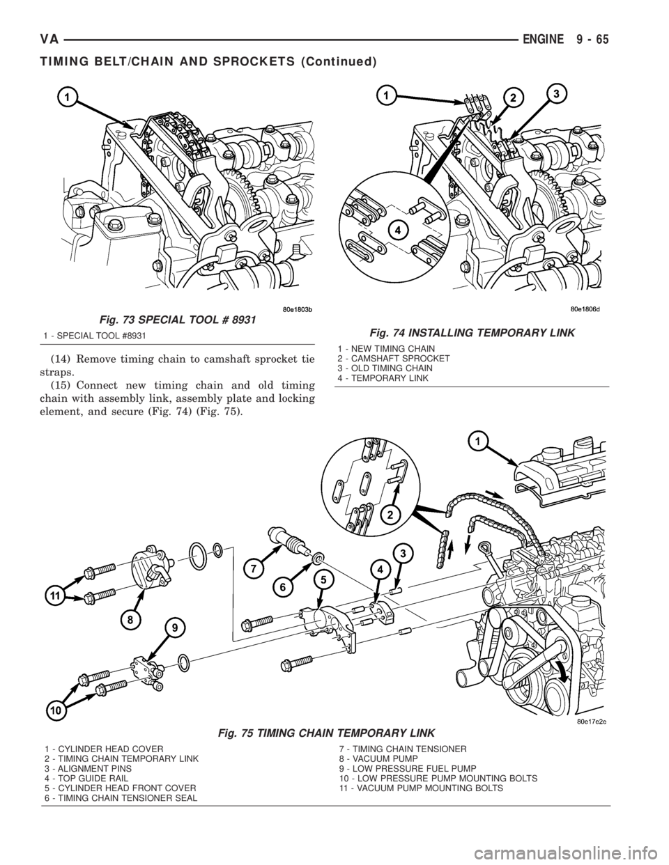
(14) Remove timing chain to camshaft sprocket tie
straps.
(15) Connect new timing chain and old timing
chain with assembly link, assembly plate and locking
element, and secure (Fig. 74) (Fig. 75).
Fig. 75 TIMING CHAIN TEMPORARY LINK
1 - CYLINDER HEAD COVER
2 - TIMING CHAIN TEMPORARY LINK
3 - ALIGNMENT PINS
4 - TOP GUIDE RAIL
5 - CYLINDER HEAD FRONT COVER
6 - TIMING CHAIN TENSIONER SEAL7 - TIMING CHAIN TENSIONER
8 - VACUUM PUMP
9 - LOW PRESSURE FUEL PUMP
10 - LOW PRESSURE PUMP MOUNTING BOLTS
11 - VACUUM PUMP MOUNTING BOLTS
Fig. 73 SPECIAL TOOL # 8931
1 - SPECIAL TOOL #8931Fig. 74 INSTALLING TEMPORARY LINK
1 - NEW TIMING CHAIN
2 - CAMSHAFT SPROCKET
3 - OLD TIMING CHAIN
4 - TEMPORARY LINK
VAENGINE 9 - 65
TIMING BELT/CHAIN AND SPROCKETS (Continued)
Page 804 of 1232
CAUTION: IT IS ESSENTIAL that the installation pro-
cedure for the timing chain is followed exactly. Fail-
ure to do so will result in severe engine damage.
INSTALLATION
INSTALLATION - TENSIONING AND SLIDE RAIL
NOTE: Carefully clean all mating surfaces with
appropriate solvents to assure that no grease or oil
is present during reassembly.
CAUTION: ENSURE THAT THE SPRING IS COR-
RECTLY INSTALLED ON THE TENSIONING CLAMP
AND SLIDE RAIL.
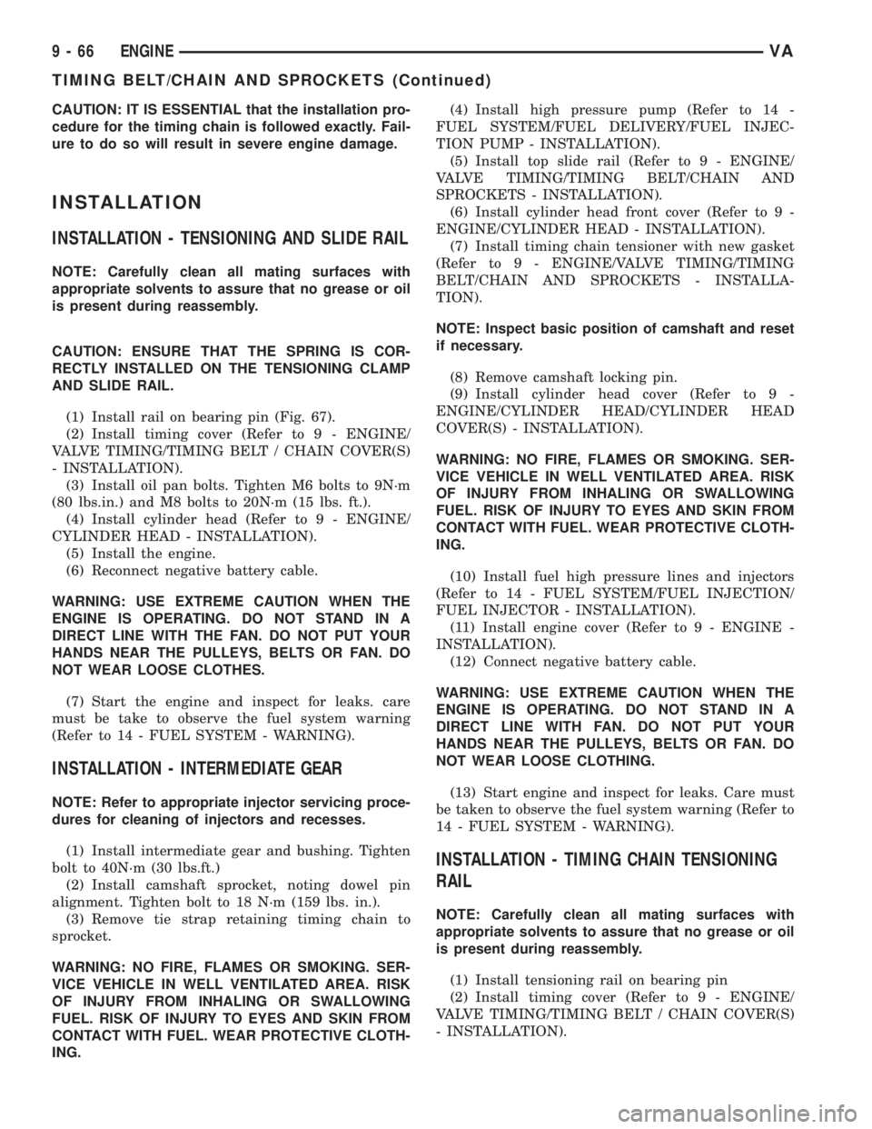
(1) Install rail on bearing pin (Fig. 67).
(2) Install timing cover (Refer to 9 - ENGINE/
VALVE TIMING/TIMING BELT / CHAIN COVER(S)
- INSTALLATION).
(3) Install oil pan bolts. Tighten M6 bolts to 9N´m
(80 lbs.in.) and M8 bolts to 20N´m (15 lbs. ft.).
(4) Install cylinder head (Refer to 9 - ENGINE/
CYLINDER HEAD - INSTALLATION).
(5) Install the engine.
(6) Reconnect negative battery cable.
WARNING: USE EXTREME CAUTION WHEN THE
ENGINE IS OPERATING. DO NOT STAND IN A
DIRECT LINE WITH THE FAN. DO NOT PUT YOUR
HANDS NEAR THE PULLEYS, BELTS OR FAN. DO
NOT WEAR LOOSE CLOTHES.
(7) Start the engine and inspect for leaks. care
must be take to observe the fuel system warning
(Refer to 14 - FUEL SYSTEM - WARNING).
INSTALLATION - INTERMEDIATE GEAR
NOTE: Refer to appropriate injector servicing proce-
dures for cleaning of injectors and recesses.
(1) Install intermediate gear and bushing. Tighten
bolt to 40N´m (30 lbs.ft.)
(2) Install camshaft sprocket, noting dowel pin
alignment. Tighten bolt to 18 N´m (159 lbs. in.).
(3) Remove tie strap retaining timing chain to
sprocket.
WARNING: NO FIRE, FLAMES OR SMOKING. SER-
VICE VEHICLE IN WELL VENTILATED AREA. RISK
OF INJURY FROM INHALING OR SWALLOWING
FUEL. RISK OF INJURY TO EYES AND SKIN FROM
CONTACT WITH FUEL. WEAR PROTECTIVE CLOTH-
ING.(4) Install high pressure pump (Refer to 14 -
FUEL SYSTEM/FUEL DELIVERY/FUEL INJEC-
TION PUMP - INSTALLATION).
(5) Install top slide rail (Refer to 9 - ENGINE/
VALVE TIMING/TIMING BELT/CHAIN AND
SPROCKETS - INSTALLATION).
(6) Install cylinder head front cover (Refer to 9 -
ENGINE/CYLINDER HEAD - INSTALLATION).
(7) Install timing chain tensioner with new gasket
(Refer to 9 - ENGINE/VALVE TIMING/TIMING
BELT/CHAIN AND SPROCKETS - INSTALLA-
TION).
NOTE: Inspect basic position of camshaft and reset
if necessary.
(8) Remove camshaft locking pin.
(9) Install cylinder head cover (Refer to 9 -
ENGINE/CYLINDER HEAD/CYLINDER HEAD
COVER(S) - INSTALLATION).
WARNING: NO FIRE, FLAMES OR SMOKING. SER-
VICE VEHICLE IN WELL VENTILATED AREA. RISK
OF INJURY FROM INHALING OR SWALLOWING
FUEL. RISK OF INJURY TO EYES AND SKIN FROM
CONTACT WITH FUEL. WEAR PROTECTIVE CLOTH-
ING.
(10) Install fuel high pressure lines and injectors
(Refer to 14 - FUEL SYSTEM/FUEL INJECTION/
FUEL INJECTOR - INSTALLATION).
(11) Install engine cover (Refer to 9 - ENGINE -
INSTALLATION).
(12) Connect negative battery cable.
WARNING: USE EXTREME CAUTION WHEN THE
ENGINE IS OPERATING. DO NOT STAND IN A
DIRECT LINE WITH FAN. DO NOT PUT YOUR
HANDS NEAR THE PULLEYS, BELTS OR FAN. DO
NOT WEAR LOOSE CLOTHING.
(13) Start engine and inspect for leaks. Care must
be taken to observe the fuel system warning (Refer to
14 - FUEL SYSTEM - WARNING).
INSTALLATION - TIMING CHAIN TENSIONING
RAIL
NOTE: Carefully clean all mating surfaces with
appropriate solvents to assure that no grease or oil
is present during reassembly.
(1) Install tensioning rail on bearing pin
(2) Install timing cover (Refer to 9 - ENGINE/
VALVE TIMING/TIMING BELT / CHAIN COVER(S)
- INSTALLATION).
9 - 66 ENGINEVA
TIMING BELT/CHAIN AND SPROCKETS (Continued)
Page 805 of 1232
(3) Install oil pan and bolts. Tighten M6 bolts to
9N´m (80 lbs.in.) and M8 bolts to 20N´m (15 lbs. ft.).
(4) Install cylinder head (Refer to 9 - ENGINE/
CYLINDER HEAD - INSTALLATION).
(5) Reconnect negative battery cable.
WARNING: USE EXTREME CAUTION WHEN THE
ENGINE IS OPERATING. DO NOT PUT YOUR
HANDS NEAR THE PULLEYS, BELTS OR FAN. DO
NOT WEAR LOOSE CLOTHES.
(6) Start the engine and inspect for leaks. Care
must be taken to observe the fuel system warning
(Refer to 14 - FUEL SYSTEM - WARNING).
ADJUSTMENTS
INSTALLATION - TIMING CHAIN
CAUTION: IT IS ESSENTIAL that the installation pro-
cedure is followed exactly. Failure to do so will
result in severe engine damage.CAUTION: Cover timing case recesses to prevent
foreign material from entering engine.
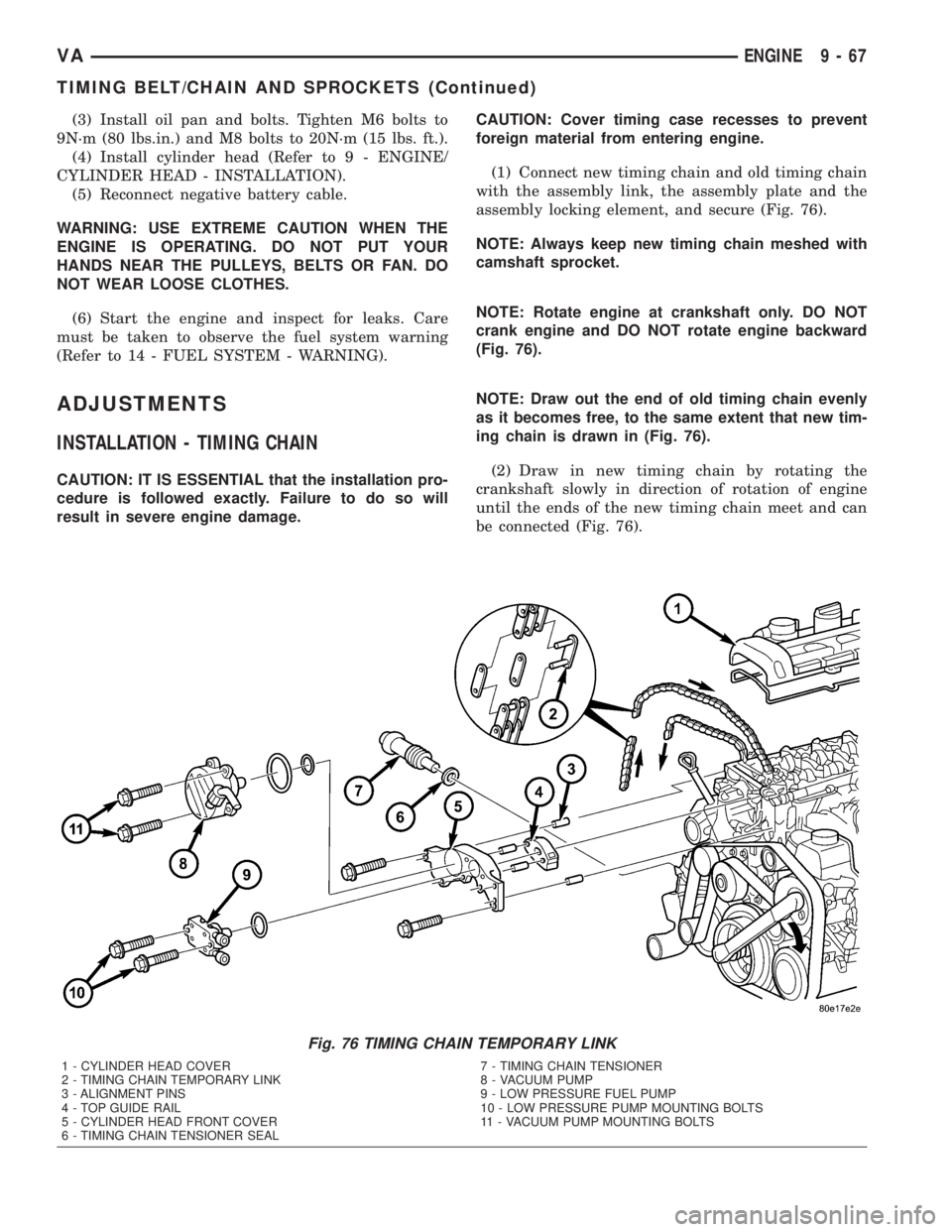
(1) Connect new timing chain and old timing chain
with the assembly link, the assembly plate and the
assembly locking element, and secure (Fig. 76).
NOTE: Always keep new timing chain meshed with
camshaft sprocket.
NOTE: Rotate engine at crankshaft only. DO NOT
crank engine and DO NOT rotate engine backward
(Fig. 76).
NOTE: Draw out the end of old timing chain evenly
as it becomes free, to the same extent that new tim-
ing chain is drawn in (Fig. 76).
(2) Draw in new timing chain by rotating the
crankshaft slowly in direction of rotation of engine
until the ends of the new timing chain meet and can
be connected (Fig. 76).
Fig. 76 TIMING CHAIN TEMPORARY LINK
1 - CYLINDER HEAD COVER
2 - TIMING CHAIN TEMPORARY LINK
3 - ALIGNMENT PINS
4 - TOP GUIDE RAIL
5 - CYLINDER HEAD FRONT COVER
6 - TIMING CHAIN TENSIONER SEAL7 - TIMING CHAIN TENSIONER
8 - VACUUM PUMP
9 - LOW PRESSURE FUEL PUMP
10 - LOW PRESSURE PUMP MOUNTING BOLTS
11 - VACUUM PUMP MOUNTING BOLTS
VAENGINE 9 - 67
TIMING BELT/CHAIN AND SPROCKETS (Continued)