2005 MERCEDES-BENZ SPRINTER automatic transmission
[x] Cancel search: automatic transmissionPage 746 of 1232
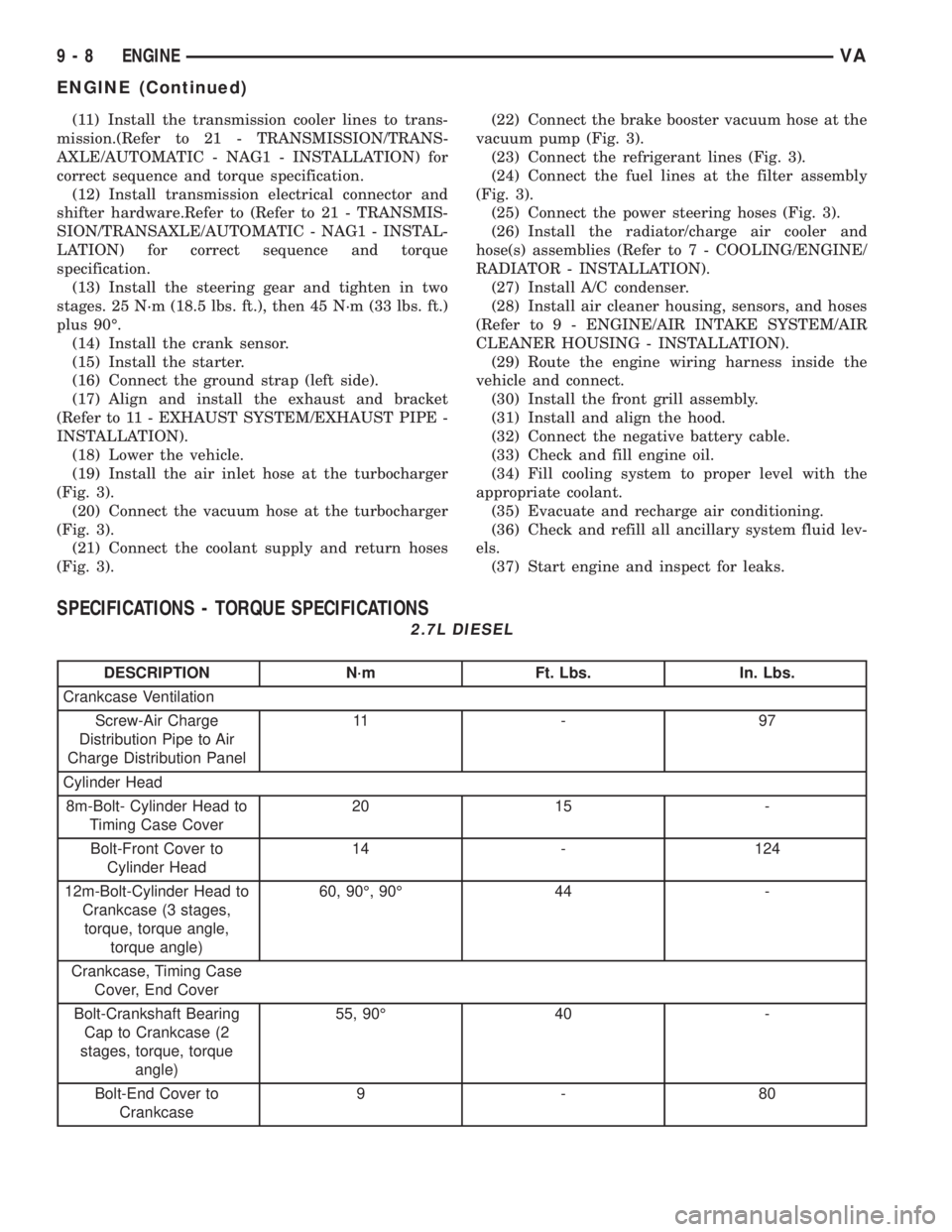
(11) Install the transmission cooler lines to trans-
mission.(Refer to 21 - TRANSMISSION/TRANS-
AXLE/AUTOMATIC - NAG1 - INSTALLATION) for
correct sequence and torque specification.
(12) Install transmission electrical connector and
shifter hardware.Refer to (Refer to 21 - TRANSMIS-
SION/TRANSAXLE/AUTOMATIC - NAG1 - INSTAL-
LATION) for correct sequence and torque
specification.
(13) Install the steering gear and tighten in two
stages. 25 N´m (18.5 lbs. ft.), then 45 N´m (33 lbs. ft.)
plus 90É.
(14) Install the crank sensor.
(15) Install the starter.
(16) Connect the ground strap (left side).
(17) Align and install the exhaust and bracket
(Refer to 11 - EXHAUST SYSTEM/EXHAUST PIPE -
INSTALLATION).
(18) Lower the vehicle.
(19) Install the air inlet hose at the turbocharger
(Fig. 3).
(20) Connect the vacuum hose at the turbocharger
(Fig. 3).
(21) Connect the coolant supply and return hoses
(Fig. 3).(22) Connect the brake booster vacuum hose at the
vacuum pump (Fig. 3).
(23) Connect the refrigerant lines (Fig. 3).
(24) Connect the fuel lines at the filter assembly
(Fig. 3).
(25) Connect the power steering hoses (Fig. 3).
(26) Install the radiator/charge air cooler and
hose(s) assemblies (Refer to 7 - COOLING/ENGINE/
RADIATOR - INSTALLATION).
(27) Install A/C condenser.
(28) Install air cleaner housing, sensors, and hoses
(Refer to 9 - ENGINE/AIR INTAKE SYSTEM/AIR
CLEANER HOUSING - INSTALLATION).
(29) Route the engine wiring harness inside the
vehicle and connect.
(30) Install the front grill assembly.
(31) Install and align the hood.
(32) Connect the negative battery cable.
(33) Check and fill engine oil.
(34) Fill cooling system to proper level with the
appropriate coolant.
(35) Evacuate and recharge air conditioning.
(36) Check and refill all ancillary system fluid lev-
els.
(37) Start engine and inspect for leaks.
SPECIFICATIONS - TORQUE SPECIFICATIONS
2.7L DIESEL
DESCRIPTION N´m Ft. Lbs. In. Lbs.
Crankcase Ventilation
Screw-Air Charge
Distribution Pipe to Air
Charge Distribution Panel11 - 9 7
Cylinder Head
8m-Bolt- Cylinder Head to
Timing Case Cover20 15 -
Bolt-Front Cover to
Cylinder Head14 - 124
12m-Bolt-Cylinder Head to
Crankcase (3 stages,
torque, torque angle,
torque angle)60, 90É, 90É 44 -
Crankcase, Timing Case
Cover, End Cover
Bolt-Crankshaft Bearing
Cap to Crankcase (2
stages, torque, torque
angle)55, 90É 40 -
Bolt-End Cover to
Crankcase9-80
9 - 8 ENGINEVA
ENGINE (Continued)
Page 777 of 1232
FLYWHEEL
REMOVAL
(1) Remove transmission (Refer to 21 - TRANS-
MISSION/TRANSAXLE/AUTOMATIC - W5J400 -
REMOVAL).
NOTE: M6x90 bolts must be used with retaining
lock to prevent damage to rear end cover.
(2) Install retaining lock for crankshaft/starter
ring gear.
NOTE: Flywheel does not need balancing or should
it be interchanged.
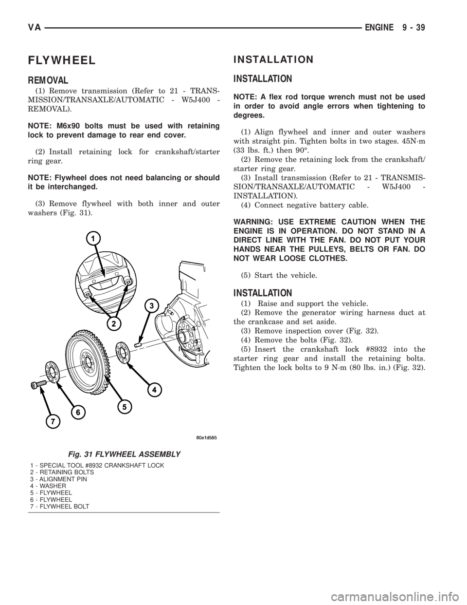
(3) Remove flywheel with both inner and outer
washers (Fig. 31).
INSTALLATION
INSTALLATION
NOTE: A flex rod torque wrench must not be used
in order to avoid angle errors when tightening to
degrees.
(1) Align flywheel and inner and outer washers
with straight pin. Tighten bolts in two stages. 45N´m
(33 lbs. ft.) then 90É.
(2) Remove the retaining lock from the crankshaft/
starter ring gear.
(3) Install transmission (Refer to 21 - TRANSMIS-
SION/TRANSAXLE/AUTOMATIC - W5J400 -
INSTALLATION).
(4) Connect negative battery cable.
WARNING: USE EXTREME CAUTION WHEN THE
ENGINE IS IN OPERATION. DO NOT STAND IN A
DIRECT LINE WITH THE FAN. DO NOT PUT YOUR
HANDS NEAR THE PULLEYS, BELTS OR FAN. DO
NOT WEAR LOOSE CLOTHES.
(5) Start the vehicle.
INSTALLATION
(1) Raise and support the vehicle.
(2) Remove the generator wiring harness duct at
the crankcase and set aside.
(3) Remove inspection cover (Fig. 32).
(4) Remove the bolts (Fig. 32).
(5) Insert the crankshaft lock #8932 into the
starter ring gear and install the retaining bolts.
Tighten the lock bolts to 9 N´m (80 lbs. in.) (Fig. 32).
Fig. 31 FLYWHEEL ASSEMBLY
1 - SPECIAL TOOL #8932 CRANKSHAFT LOCK
2 - RETAINING BOLTS
3 - ALIGNMENT PIN
4 - WASHER
5 - FLYWHEEL
6 - FLYWHEEL
7 - FLYWHEEL BOLT
VAENGINE 9 - 39
Page 861 of 1232
STEERING
TABLE OF CONTENTS
page page
STEERING
DESCRIPTION..........................1
OPERATION............................1
DIAGNOSIS AND TESTING - POWER
STEERING SYSTEM....................2COLUMN...............................5
GEAR..................................8
LINKAGE..............................10
PUMP.................................12
STEERING
DESCRIPTION
CAUTION: Mopar ATF+4 Automatic Transmission
fluid or equivalent is to be used in the power steer-
ing system. No other power steering or automatic
transmission fluid is to be used in the system.
Damage may result to the power steering pump and
system if any other fluid is used, and do not over-
fill.
Power steering systems consist of:
²Steering column
²Rack and pinion steering gear
²Belt driven hydraulic steering pump
²Pump pressure and return hoses
²Oil Cooler
OPERATION
The steering column shaft is attached to the gear
pinion. The rotation of the pinion moves the gear
rack from side-to-side. This lateral action of the rack
pushes and pulls the tie rods to change the direction
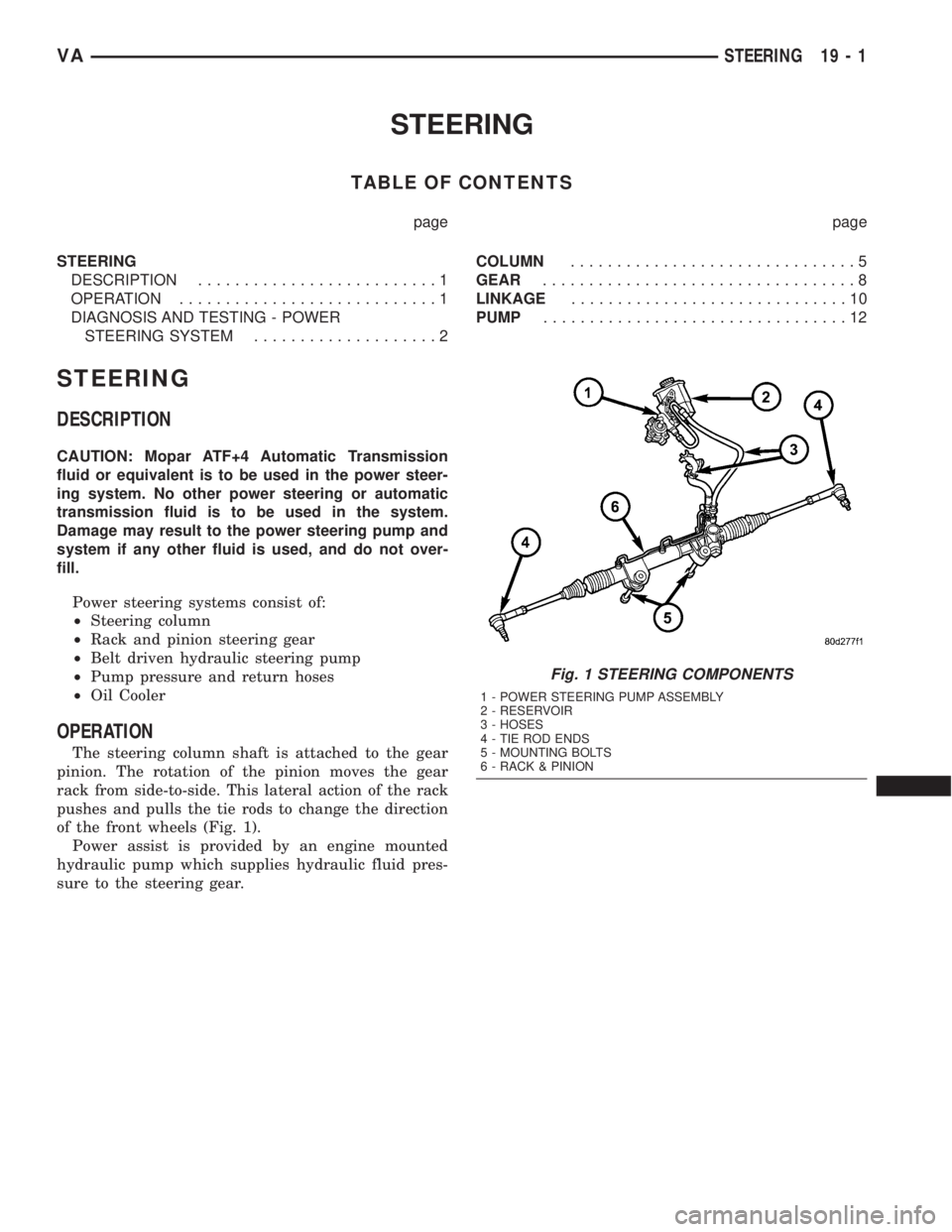
of the front wheels (Fig. 1).
Power assist is provided by an engine mounted
hydraulic pump which supplies hydraulic fluid pres-
sure to the steering gear.
Fig. 1 STEERING COMPONENTS
1 - POWER STEERING PUMP ASSEMBLY
2 - RESERVOIR
3 - HOSES
4 - TIE ROD ENDS
5 - MOUNTING BOLTS
6 - RACK & PINION
VASTEERING 19 - 1
Page 872 of 1232
PUMP
TABLE OF CONTENTS
page page
PUMP
DESCRIPTION.........................12
OPERATION...........................12
DIAGNOSIS AND TESTING - PUMP LEAKAGE . 12
STANDARD PROCEDURE
STANDARD PROCEDURE - POWER
STEERING PUMP - INITIAL OPERATION....12
STANDARD PROCEDURE - FLUSHING
POWER STEERING SYSTEM............13
REMOVAL.............................13
INSTALLATION.........................13
SPECIFICATIONS - TORQUE CHART........14
FLUID
STANDARD PROCEDURE
POWER STEERING PUMP FILL AND BLEED
PROCEDURE........................14FLUID COOLER TUBE
REMOVAL.............................14
INSTALLATION.........................14
HOSES
REMOVAL
REMOVAL - PRESSURE HOSE...........15
REMOVAL - RETURN LINE FROM PUMP TO
COOLER TUBE.......................15
REMOVAL - RETURN HOSE FROM GEAR
TO COOLER TUBE....................15
INSTALLATION
INSTALLATION - PRESSURE HOSE.......15
INSTALLATION - RETURN LINE FROM
PUMP TO COOLER TUBE...............15
INSTALLATION - RETURN HOSE FROM
GEAR TO COOLER TUBE...............15
PUMP
DESCRIPTION
CAUTION: Mopar ATF+4 Automatic Transmission
fluid or equivalent is to be used in the power steer-
ing system. No other power steering or automatic
transmission fluid is to be used in the system.
Damage may result to the power steering pump and
system if any other fluid is used, and do not over-
fill.
The pump is connected to the steering gear via the
pressure hose and the return hose. The pump shaft
has a pressed-on pulley that is belt driven by the
crankshaft pulley.
All vehicles are equipped with a power steering
fluid cooler.
NOTE: Power steering pumps are not interchange-
able with pumps installed on other vehicles.
OPERATION
Hydraulic pressure is provided for the power steer-
ing gear by the belt driven power steering pump. The
power steering pumps are constant flow rate and dis-
placement, vane-type pumps.
DIAGNOSIS AND TESTING - PUMP LEAKAGE
The pump is serviced as an assembly and should
not be disassembled. The plastic pump reservoir and
the reservoir o-rings can be replaced.
Check for leaks in the following areas:
²Pump shaft seal behind the pulley
²Pump to reservoir O-ring
²Reservoir cap
²Pressure and return lines
²Flow control valve fitting
STANDARD PROCEDURE
STANDARD PROCEDURE - POWER STEERING
PUMP - INITIAL OPERATION
WARNING: THE FLUID LEVEL SHOULD BE
CHECKED WITH ENGINE OFF TO PREVENT INJURY
FROM MOVING COMPONENTS.
CAUTION: Mopar ATF+4 Automatic Transmission
fluid or equivalent is to be used in the power steer-
ing system. No other power steering or automatic
transmission fluid is to be used in the system.
Damage may result to the power steering pump and
system if any other fluid is used, and do not over-
fill.
19 - 12 PUMPVA
Page 874 of 1232
SPECIFICATIONS - TORQUE CHART
TORQUE SPECIFICATIONS
DESCRIPTION N´m Ft. Lbs. In. Lbs.
Power Steering Pump To
Timing Case Cover/
Support21 15 185
High Pressure Flexible
Hose To Power Steering
Pump38 28 336
Power Steering Pulley To
Pump30 22 265
FLUID
STANDARD PROCEDURE
POWER STEERING PUMP FILL AND BLEED
PROCEDURE
(1) Remove the cap from the fluid reservoir.
Check cap seal for damage and replace if
needed.
(2) Fill the power steering pump with Mopar
ATF+4 Automatic Transmission fluid or equivalent.
Do not fill fluid beyond the MAX mark.
(3) Raise the vehicles front wheels off the ground.
(4) With the engine off turn the steering wheel
from right to left.Perform this step until all the
bubble formations can no longer be seen in the
power steering reservoir.
(5) Start the engine and turn the steering wheel
with the engine at idle speed then shut the engine off
and check for correct oil level and no bubble in the
system.
(6) Reinstall power steering cap tightly.
(7) Test the system for leaks and proper operation.
FLUID COOLER TUBE
REMOVAL
(1) Siphon as much power steering fluid as possi-
ble out of the reservoir.
(2) Remove the grille (Refer to 23 - BODY/EXTE-
RIOR/GRILLE - REMOVAL).
(3) Remove the left headlight assembly.
(4) Disconnect the return lines from the cooler
tube.
(5) Remove the radiator clips (2).
(6) Remove the heat shield bolt for the turbo at
the core support.
(7) Remove the right headlight assembly.(8) Remove the core support bolts (4) and discon-
nect the hood latch cable.
(9) Remove the fan bracket bolts (4) to the radiator
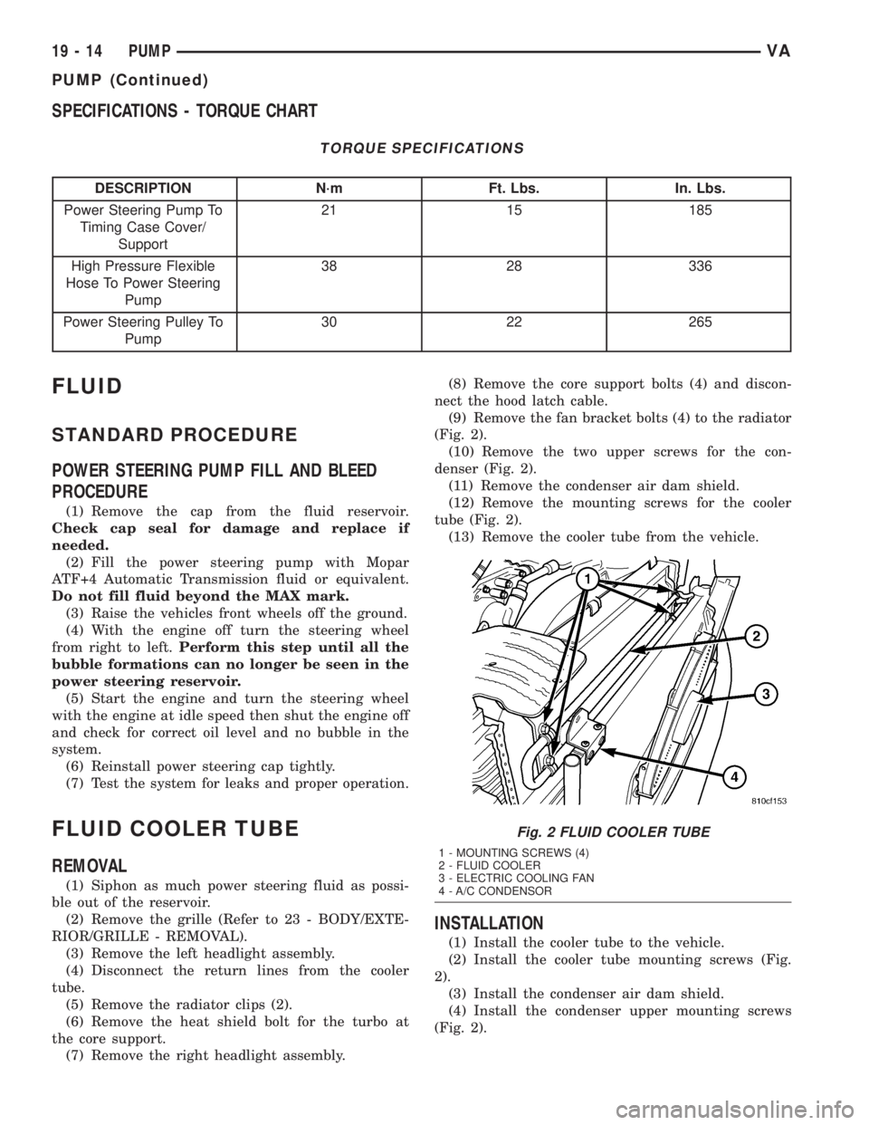
(Fig. 2).
(10) Remove the two upper screws for the con-
denser (Fig. 2).
(11) Remove the condenser air dam shield.
(12) Remove the mounting screws for the cooler
tube (Fig. 2).
(13) Remove the cooler tube from the vehicle.
INSTALLATION
(1) Install the cooler tube to the vehicle.
(2) Install the cooler tube mounting screws (Fig.
2).
(3) Install the condenser air dam shield.
(4) Install the condenser upper mounting screws
(Fig. 2).
Fig. 2 FLUID COOLER TUBE
1 - MOUNTING SCREWS (4)
2 - FLUID COOLER
3 - ELECTRIC COOLING FAN
4 - A/C CONDENSOR
19 - 14 PUMPVA
PUMP (Continued)
Page 877 of 1232
TRANSMISSION
AUTOMATIC TRANSMISSION - NAG1
TABLE OF CONTENTS
page page
AUTOMATIC TRANSMISSION - NAG1
DESCRIPTION..........................2
OPERATION............................4
DIAGNOSIS AND TESTING
DIAGNOSIS AND TESTING - AUTOMATIC
TRANSMISSION......................23
DIAGNOSIS AND TESTING - PRELIMINARY . 23
DIAGNOSIS AND TESTING - ROAD
TESTING............................23
DIAGNOSIS AND TESTING - AUTOMATIC
TRANSMISSION......................24
STANDARD PROCEDURE - ALUMINUM
THREAD REPAIR......................27
REMOVAL.............................27
DISASSEMBLY.........................30
ASSEMBLY............................34
INSTALLATION.........................41
SCHEMATICS AND DIAGRAMS............47
SPECIFICATIONS - NAG1 AUTOMATIC
TRANSMISSION......................68
SPECIAL TOOLS - NAG1 AUTOMATIC
TRANSMISSION......................69
DRIVING CLUTCHES
DESCRIPTION.........................72
OPERATION...........................72
DRIVING CLUTCH K1
DISASSEMBLY.........................74
ASSEMBLY............................75
DRIVING CLUTCH K2
DISASSEMBLY.........................76
ASSEMBLY............................78
DRIVING CLUTCH K3
DISASSEMBLY.........................80
ASSEMBLY............................80
ELECTROHYDRAULIC UNIT
DESCRIPTION.........................82
OPERATION...........................87
REMOVAL.............................92
DISASSEMBLY.........................92
ASSEMBLY............................95
INSTALLATION........................100
FLUID AND FILTER
DESCRIPTION........................101
OPERATION..........................101DIAGNOSIS AND TESTING
DIAGNOSIS AND TESTING - EFFECTS OF
INCORRECT FLUID LEVEL.............102
DIAGNOSIS AND TESTING - CAUSES OF
BURNT FLUID.......................102
DIAGNOSIS AND TESTING - FLUID
CONTAMINATION....................102
STANDARD PROCEDURE
STANDARD PROCEDURE - CHECK OIL
LEVEL.............................102
STANDARD PROCEDURE - TRANSMISSION
FILL...............................103
STANDARD PROCEDURE - FLUID/FILTER
SERVICE...........................104
FREEWHEELING CLUTCH
DESCRIPTION........................105
OPERATION..........................105
DISASSEMBLY........................106
ASSEMBLY...........................107
GEARSHIFT CABLE
DIAGNOSIS AND TESTING - GEARSHIFT
CABLE.............................109
REMOVAL............................109
INSTALLATION........................109
HOLDING CLUTCHES
DESCRIPTION........................111
OPERATION..........................112
HOLDING CLUTCH B1
DISASSEMBLY........................112
ASSEMBLY...........................113
HOLDING CLUTCH B2
DISASSEMBLY........................115
ASSEMBLY...........................116
INPUT SPEED SENSORS
DESCRIPTION........................119
OPERATION..........................119
OIL PUMP
DESCRIPTION........................120
OPERATION..........................120
DISASSEMBLY........................120
ASSEMBLY...........................121
OUTPUT SHAFT BEARING
REMOVAL............................122
INSTALLATION........................122
VATRANSMISSION 21 - 1
Page 878 of 1232
OUTPUT SHAFT SEAL
REMOVAL............................125
INSTALLATION........................125
PARK LOCK CABLE
REMOVAL............................125
INSTALLATION........................126
PISTONS
DESCRIPTION........................128
OPERATION..........................128
PLANETARY GEARTRAIN
DESCRIPTION........................130
OPERATION..........................130
DISASSEMBLY........................131
ASSEMBLY...........................131
SHIFT MECHANISM
DESCRIPTION........................133
OPERATION..........................133
REMOVAL............................134
INSTALLATION........................135
SOLENOID
DESCRIPTION........................136OPERATION..........................138
TEMPERATURE SENSOR/PARK-NEUTRAL
CONTACT
DESCRIPTION
DESCRIPTION - PARK/NEUTRAL CONTACT . 139
DESCRIPTION - TRANSMISSION
TEMPERATURE SENSOR..............140
OPERATION
OPERATION - PARK/NEUTRAL CONTACT . . 140
OPERATION - TRANSMISSION
TEMPERATURE SENSOR..............141
TORQUE CONVERTER
DESCRIPTION........................141
OPERATION..........................143
REMOVAL............................146
INSTALLATION........................146
TORQUE CONVERTER HUB SEAL
REMOVAL............................147
INSTALLATION........................147
AUTOMATIC TRANSMISSION -
NAG1
DESCRIPTION
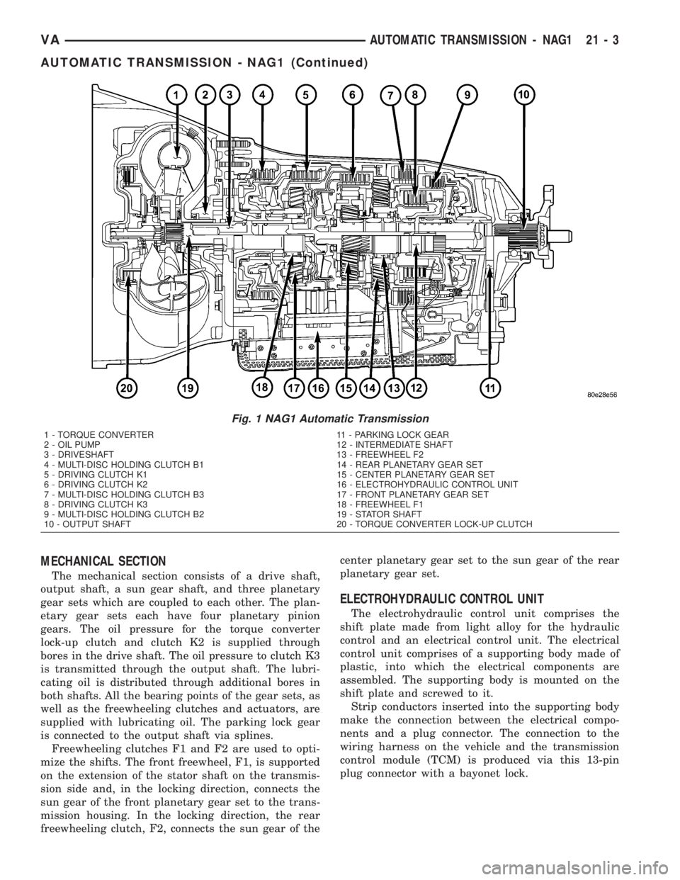
The NAG1 automatic transmission (Fig. 1) is an
electronically controlled 5-speed transmission with a
lock-up clutch in the torque converter. The ratios for
the gear stages are obtained by 3 planetary gear sets.
Fifth gear is designed as an overdrive with a high-
speed ratio.
The gears are actuated electronically/hydraulically.
The gears are shifted by means of an appropriate
combination of three multi-disc holding clutches,
three multi-disc driving clutches, and two freewheel-
ing clutches.
Electronic transmission control enables precise
adaptation of pressures to the respective operating
conditions and to the engine output during the shift
phase which results in a significant improvement in
shift quality.
Furthermore, it offers the advantage of a flexible
adaptation to various vehicle and engines.
Basically, the automatic transmission with elec-
tronic control offers the following advantages:
²Reduces fuel consumption.
²Improved shift comfort.
²More favourable step-up through the five gears.
²Increased service life and reliability.
²Lower maintenance costs.
TRANSMISSION IDENTIFICATION
The transmission name, NAG1, means New Auto-
matic Gearbox, generation 1.
The transmission can be generically identified
visually by the presence of a round 13-way connector
located near the front corner of the transmission oil
pan, on the right side. Specific transmission informa-
tion can be found stamped into a pad on the left side
of the transmission, above the oil pan rail.
TRANSMISSION GEAR RATIOS
The gear ratios for the NAG1 automatic transmis-
sion are as follows:
1st Gear.............................3.59:1
2nd Gear............................2.19:1
3rd Gear............................1.41:1
4th Gear............................1.00:1
5th Gear............................0.83:1
Reverse.............................3.16:1
TRANSMISSION HOUSING
The converter housing and transmission are made
from a light alloy. These are bolted together and cen-
tered via the outer multi-disc carrier of multi-disc
holding clutch, B1. A coated intermediate plate pro-
vides the sealing. The oil pump and the outer multi-
disc carrier of the multi-disc holding clutch, B1, are
bolted to the converter housing. The stator shaft is
pressed into it and prevented from rotating by
splines. The electrohydraulic unit is bolted to the
transmission housing from underneath. A sheet
metal steel oil pan forms the closure.
21 - 2 AUTOMATIC TRANSMISSION - NAG1VA
Page 879 of 1232
MECHANICAL SECTION
The mechanical section consists of a drive shaft,
output shaft, a sun gear shaft, and three planetary
gear sets which are coupled to each other. The plan-
etary gear sets each have four planetary pinion
gears. The oil pressure for the torque converter
lock-up clutch and clutch K2 is supplied through
bores in the drive shaft. The oil pressure to clutch K3
is transmitted through the output shaft. The lubri-
cating oil is distributed through additional bores in
both shafts. All the bearing points of the gear sets, as
well as the freewheeling clutches and actuators, are
supplied with lubricating oil. The parking lock gear
is connected to the output shaft via splines.
Freewheeling clutches F1 and F2 are used to opti-
mize the shifts. The front freewheel, F1, is supported
on the extension of the stator shaft on the transmis-
sion side and, in the locking direction, connects the
sun gear of the front planetary gear set to the trans-
mission housing. In the locking direction, the rear
freewheeling clutch, F2, connects the sun gear of thecenter planetary gear set to the sun gear of the rear
planetary gear set.
ELECTROHYDRAULIC CONTROL UNIT
The electrohydraulic control unit comprises the
shift plate made from light alloy for the hydraulic
control and an electrical control unit. The electrical
control unit comprises of a supporting body made of
plastic, into which the electrical components are
assembled. The supporting body is mounted on the
shift plate and screwed to it.
Strip conductors inserted into the supporting body
make the connection between the electrical compo-
nents and a plug connector. The connection to the
wiring harness on the vehicle and the transmission
control module (TCM) is produced via this 13-pin
plug connector with a bayonet lock.
Fig. 1 NAG1 Automatic Transmission
1 - TORQUE CONVERTER 11 - PARKING LOCK GEAR
2 - OIL PUMP 12 - INTERMEDIATE SHAFT
3 - DRIVESHAFT 13 - FREEWHEEL F2
4 - MULTI-DISC HOLDING CLUTCH B1 14 - REAR PLANETARY GEAR SET
5 - DRIVING CLUTCH K1 15 - CENTER PLANETARY GEAR SET
6 - DRIVING CLUTCH K2 16 - ELECTROHYDRAULIC CONTROL UNIT
7 - MULTI-DISC HOLDING CLUTCH B3 17 - FRONT PLANETARY GEAR SET
8 - DRIVING CLUTCH K3 18 - FREEWHEEL F1
9 - MULTI-DISC HOLDING CLUTCH B2 19 - STATOR SHAFT
10 - OUTPUT SHAFT 20 - TORQUE CONVERTER LOCK-UP CLUTCH
VAAUTOMATIC TRANSMISSION - NAG1 21 - 3
AUTOMATIC TRANSMISSION - NAG1 (Continued)