2005 MERCEDES-BENZ SPRINTER automatic transmission
[x] Cancel search: automatic transmissionPage 127 of 1232
²Low and High ATF Temperature.
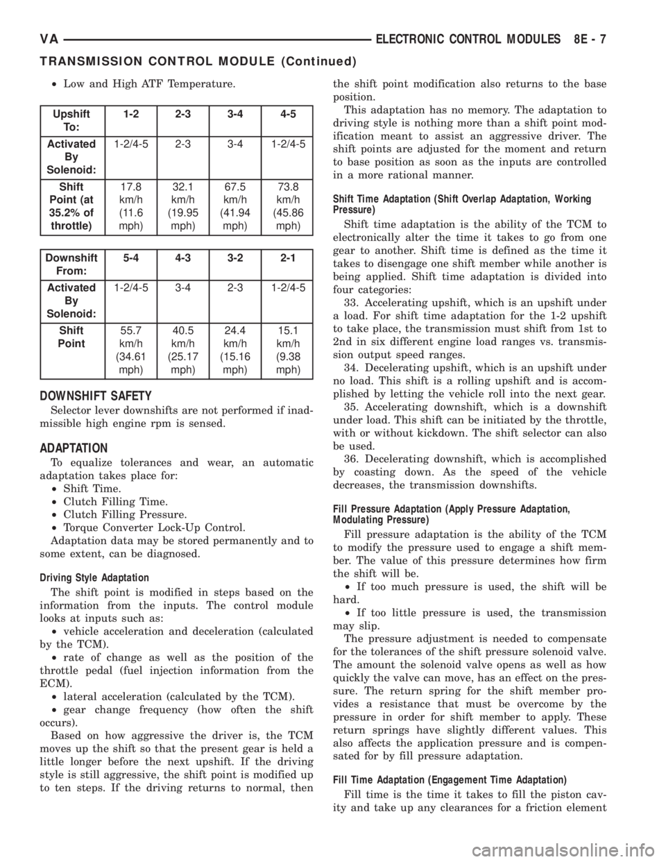
Upshift
To :1-2 2-3 3-4 4-5
Activated
By
Solenoid:1-2/4-5 2-3 3-4 1-2/4-5
Shift
Point (at
35.2% of
throttle)17.8
km/h
(11.6
mph)32.1
km/h
(19.95
mph)67.5
km/h
(41.94
mph)73.8
km/h
(45.86
mph)
Downshift
From:5-4 4-3 3-2 2-1
Activated
By
Solenoid:1-2/4-5 3-4 2-3 1-2/4-5
Shift
Point55.7
km/h
(34.61
mph)40.5
km/h
(25.17
mph)24.4
km/h
(15.16
mph)15.1
km/h
(9.38
mph)
DOWNSHIFT SAFETY
Selector lever downshifts are not performed if inad-
missible high engine rpm is sensed.
ADAPTATION
To equalize tolerances and wear, an automatic
adaptation takes place for:
²Shift Time.
²Clutch Filling Time.
²Clutch Filling Pressure.
²Torque Converter Lock-Up Control.
Adaptation data may be stored permanently and to
some extent, can be diagnosed.
Driving Style Adaptation
The shift point is modified in steps based on the
information from the inputs. The control module
looks at inputs such as:
²vehicle acceleration and deceleration (calculated
by the TCM).
²rate of change as well as the position of the
throttle pedal (fuel injection information from the
ECM).
²lateral acceleration (calculated by the TCM).
²gear change frequency (how often the shift
occurs).
Based on how aggressive the driver is, the TCM
moves up the shift so that the present gear is held a
little longer before the next upshift. If the driving
style is still aggressive, the shift point is modified up
to ten steps. If the driving returns to normal, thenthe shift point modification also returns to the base
position.
This adaptation has no memory. The adaptation to
driving style is nothing more than a shift point mod-
ification meant to assist an aggressive driver. The
shift points are adjusted for the moment and return
to base position as soon as the inputs are controlled
in a more rational manner.
Shift Time Adaptation (Shift Overlap Adaptation, Working
Pressure)
Shift time adaptation is the ability of the TCM to
electronically alter the time it takes to go from one
gear to another. Shift time is defined as the time it
takes to disengage one shift member while another is
being applied. Shift time adaptation is divided into
four categories:
33. Accelerating upshift, which is an upshift under
a load. For shift time adaptation for the 1-2 upshift
to take place, the transmission must shift from 1st to
2nd in six different engine load ranges vs. transmis-
sion output speed ranges.
34. Decelerating upshift, which is an upshift under
no load. This shift is a rolling upshift and is accom-
plished by letting the vehicle roll into the next gear.
35. Accelerating downshift, which is a downshift
under load. This shift can be initiated by the throttle,
with or without kickdown. The shift selector can also
be used.
36. Decelerating downshift, which is accomplished
by coasting down. As the speed of the vehicle
decreases, the transmission downshifts.
Fill Pressure Adaptation (Apply Pressure Adaptation,
Modulating Pressure)
Fill pressure adaptation is the ability of the TCM
to modify the pressure used to engage a shift mem-
ber. The value of this pressure determines how firm
the shift will be.
²If too much pressure is used, the shift will be
hard.
²If too little pressure is used, the transmission
may slip.
The pressure adjustment is needed to compensate
for the tolerances of the shift pressure solenoid valve.
The amount the solenoid valve opens as well as how
quickly the valve can move, has an effect on the pres-
sure. The return spring for the shift member pro-
vides a resistance that must be overcome by the
pressure in order for shift member to apply. These
return springs have slightly different values. This
also affects the application pressure and is compen-
sated for by fill pressure adaptation.
Fill Time Adaptation (Engagement Time Adaptation)
Fill time is the time it takes to fill the piston cav-
ity and take up any clearances for a friction element
VAELECTRONIC CONTROL MODULES 8E - 7
TRANSMISSION CONTROL MODULE (Continued)
Page 143 of 1232
WARNING: EXPLOSIVE HYDROGEN GAS FORMS IN
AND AROUND THE BATTERY. DO NOT SMOKE, USE
FLAME, OR CREATE SPARKS NEAR THE BATTERY.
PERSONAL INJURY AND/OR VEHICLE DAMAGE MAY
RESULT.
WARNING: THE BATTERY CONTAINS SULFURIC
ACID, WHICH IS POISONOUS AND CAUSTIC. AVOID
CONTACT WITH THE SKIN, EYES, OR CLOTHING.
IN THE EVENT OF CONTACT, FLUSH WITH WATER
AND CALL A PHYSICIAN IMMEDIATELY. KEEP OUT
OF THE REACH OF CHILDREN.
WARNING: IF THE BATTERY IS EQUIPPED WITH
REMOVABLE CELL CAPS, BE CERTAIN THAT EACH
OF THE CELL CAPS IS IN PLACE AND TIGHT BEFORE
THE BATTERY IS RETURNED TO SERVICE. PER-
SONAL INJURY AND/OR VEHICLE DAMAGE MAY
RESULT FROM LOOSE OR MISSING CELL CAPS.
The following operation will require a voltmeter
accurate to 1/10 (0.10) volt. Before performing this
test, be certain that the following procedures are
accomplished:
²The battery is fully-charged and tested. (Refer to
8 - ELECTRICAL/BATTERY SYSTEM/BATTERY -
STANDARD PROCEDURE).
²Fully engage the parking brake.
²Place the automatic transmission gearshift selec-
tor lever in the Park position.
²Verify that all lamps and accessories are turned
off.
²Prevent the engine from starting.
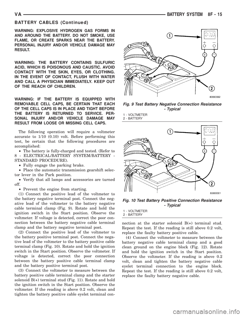
(1) Connect the positive lead of the voltmeter to
the battery negative terminal post. Connect the neg-
ative lead of the voltmeter to the battery negative
cable terminal clamp (Fig. 9). Rotate and hold the
ignition switch in the Start position. Observe the
voltmeter. If voltage is detected, correct the poor con-
nection between the battery negative cable terminal
clamp and the battery negative terminal post.
(2) Connect the positive lead of the voltmeter to
the battery positive terminal post. Connect the nega-
tive lead of the voltmeter to the battery positive cable
terminal clamp (Fig. 10). Rotate and hold the ignition
switch in the Start position. Observe the voltmeter. If
voltage is detected, correct the poor connection
between the battery positive cable terminal clamp
and the battery positive terminal post.
(3) Connect the voltmeter to measure between the
battery positive cable terminal clamp and the starter
solenoid B(+) terminal stud (Fig. 11). Rotate and hold
the ignition switch in the Start position. Observe the
voltmeter. If the reading is above 0.2 volt, clean and
tighten the battery positive cable eyelet terminal con-nection at the starter solenoid B(+) terminal stud.
Repeat the test. If the reading is still above 0.2 volt,
replace the faulty battery positive cable.
(4) Connect the voltmeter to measure between the
battery negative cable terminal clamp and a good
clean ground on the engine block (Fig. 12). Rotate
and hold the ignition switch in the Start position.
Observe the voltmeter. If the reading is above 0.2
volt, clean and tighten the battery negative cable
eyelet terminal connection to the engine block.
Repeat the test. If the reading is still above 0.2 volt,
replace the faulty battery negative cable.
Fig. 9 Test Battery Negative Connection Resistance
- Typical
1 - VOLTMETER
2 - BATTERY
Fig. 10 Test Battery Positive Connection Resistance
- Typical
1 - VOLTMETER
2 - BATTERY
VABATTERY SYSTEM 8F - 15
BATTERY CABLES (Continued)
Page 152 of 1232
STARTING SYSTEM
TABLE OF CONTENTS
page page
STARTING SYSTEM
DESCRIPTION.........................24
OPERATION...........................24
DIAGNOSIS AND TESTING - STARTING
SYSTEM............................25
SPECIFICATIONS
TORQUE - STARTER - DIESEL...........29
SPECIFICATIONS - STARTER MOTOR -
DIESEL.............................29STARTER MOTOR
DIAGNOSIS AND TESTING - STARTER
MOTOR .............................29
REMOVAL.............................30
INSTALLATION.........................31
STARTER MOTOR RELAY
DESCRIPTION.........................31
REMOVAL.............................31
INSTALLATION.........................32
STARTING SYSTEM
DESCRIPTION
The starting system consists of:
²Starter relay
²Starter motor (including an integral starter sole-
noid)
Other components to be considered as part of start-
ing system are:
²Battery
²Battery cables
²Ignition switch and key lock cylinder
²Park/neutral position switch (automatic trans-
mission)
²Wire harnesses and connections.
The Battery, Starting, and Charging systems oper-
ate in conjunction with one another, and must be
tested as a complete system. For correct operation of
starting/charging systems, all components used in
these 3 systems must perform within specifications.
When attempting to diagnose any of these systems, it
is important that you keep their interdependency in
mind.
The diagnostic procedures used in each of these
groups include the most basic conventional diagnostic
methods, to the more sophisticated On-Board Diag-
nostics (OBD) built into the Engine Control Module
(ECM). Use of an induction-type milliampere amme-
ter, volt/ohmmeter, battery charger, carbon pile rheo-
stat (load tester), and 12-volt test lamp may be
required.
Certain starting system components are monitored
by the ECM and may produce a Diagnostic Trouble
Code (DTC).
OPERATION
The starting system components form two separate
circuits. A high-amperage feed circuit that feeds thestarter motor high-amperage, and a low-amperage
control circuit that operates on less than 20 amperes.
The high-amperage feed circuit components include
the battery, the battery cables, the contact disc por-
tion of the starter solenoid, and the starter motor
itself. The low-amperage control circuit components
include the ignition switch, the park/neutral position
switch (automatic transmission), the starter relay,
the electromagnetic windings of the starter solenoid,
and the connecting wire harness components.
If the vehicle is equipped with an automatic trans-
mission, battery voltage is supplied through the low-
amperage control circuit to the coil battery terminal
of the starter relay when the ignition switch is
turned to the momentary Start position. The park/
neutral position switch is installed in series between
the starter relay coil ground terminal and ground.
This normally open switch prevents the starter relay
from being energized and the starter motor from
operating unless the automatic transmission gear
selector is in the Neutral or Park positions.
When the starter relay coil is energized, the nor-
mally open relay contacts close. The relay contacts
connect the relay common feed terminal to the relay
normally open terminal. The closed relay contacts
energize the starter solenoid coil windings.
The energized solenoid pull-in coil pulls in the sole-
noid plunger. The solenoid plunger pulls the shift
lever in the starter motor. This engages the starter
overrunning clutch and pinion gear with the starter
ring gear on the manual transmission flywheel or on
the automatic transmission torque converter or
torque converter drive plate.
As the solenoid plunger reaches the end of its
travel, the solenoid contact disc completes the high-
amperage starter feed circuit and energizes the sole-
noid plunger hold-in coil. Current now flows between
the solenoid battery terminal and the starter motor,
energizing the starter.
8F - 24 STARTING SYSTEMVA
Page 156 of 1232
switch in Start position. Observe voltmeter. If read-
ing is above 0.2 volt, clean and tighten battery cable
connection at solenoid. Repeat test. If reading is still
above 0.2 volt, replace faulty positive battery cable.
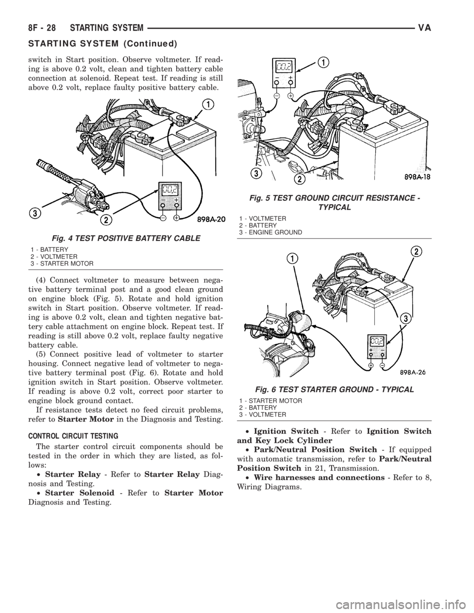
(4) Connect voltmeter to measure between nega-
tive battery terminal post and a good clean ground
on engine block (Fig. 5). Rotate and hold ignition
switch in Start position. Observe voltmeter. If read-
ing is above 0.2 volt, clean and tighten negative bat-
tery cable attachment on engine block. Repeat test. If
reading is still above 0.2 volt, replace faulty negative
battery cable.
(5) Connect positive lead of voltmeter to starter
housing. Connect negative lead of voltmeter to nega-
tive battery terminal post (Fig. 6). Rotate and hold
ignition switch in Start position. Observe voltmeter.
If reading is above 0.2 volt, correct poor starter to
engine block ground contact.
If resistance tests detect no feed circuit problems,
refer toStarter Motorin the Diagnosis and Testing.
CONTROL CIRCUIT TESTING
The starter control circuit components should be
tested in the order in which they are listed, as fol-
lows:
²Starter Relay- Refer toStarter RelayDiag-
nosis and Testing.
²Starter Solenoid- Refer toStarter Motor
Diagnosis and Testing.²Ignition Switch- Refer toIgnition Switch
and Key Lock Cylinder
²Park/Neutral Position Switch- If equipped
with automatic transmission, refer toPark/Neutral
Position Switchin 21, Transmission.
²Wire harnesses and connections- Refer to 8,
Wiring Diagrams.
Fig. 4 TEST POSITIVE BATTERY CABLE
1 - BATTERY
2 - VOLTMETER
3 - STARTER MOTOR
Fig. 5 TEST GROUND CIRCUIT RESISTANCE -
TYPICAL
1 - VOLTMETER
2 - BATTERY
3 - ENGINE GROUND
Fig. 6 TEST STARTER GROUND - TYPICAL
1 - STARTER MOTOR
2 - BATTERY
3 - VOLTMETER
8F - 28 STARTING SYSTEMVA
STARTING SYSTEM (Continued)
Page 172 of 1232
INSTRUMENT CLUSTER
DESCRIPTION
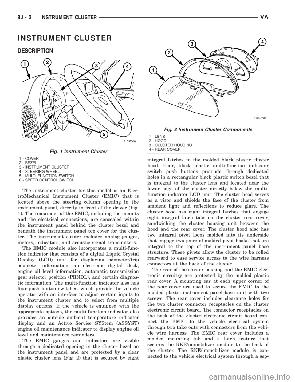
The instrument cluster for this model is an Elec-
troMechanical Instrument Cluster (EMIC) that is
located above the steering column opening in the
instrument panel, directly in front of the driver (Fig.
1). The remainder of the EMIC, including the mounts
and the electrical connections, are concealed within
the instrument panel behind the cluster bezel and
beneath the instrument panel top cover for the clus-
ter. The instrument cluster includes analog gauges,
meters, indicators, and acoustic signal transmitters.
The EMIC module also incorporates a multi-func-
tion indicator that consists of a digital Liquid Crystal
Display (LCD) unit for displaying odometer/trip
odometer information, an electronic digital clock,
engine oil level information, automatic transmission
gear selector position (PRNDL), and certain diagnos-
tic information. The multi-function indicator also has
four push button switches, which provide the vehicle
operator with an interface to adjust certain inputs to
the instrument cluster and to select from multiple
display options. If the vehicle is equipped with the
appropriate options, the multi-function indicator also
provides an outside ambient temperature indicator
display and an Active Service SYStem (ASSYST)
engine oil maintenance indicator to display engine oil
level and maintenance reminders.
The EMIC gauges and indicators are visible
through a dedicated opening in the cluster bezel on
the instrument panel and are protected by a clear
plastic cluster lens (Fig. 2) that is secured by eightintegral latches to the molded black plastic cluster
hood. Four, black plastic multi-function indicator
switch push buttons protrude through dedicated
holes in a rectangular black plastic switch bezel that
is integral to the cluster lens and located near the
lower edge of the cluster directly below the multi-
function indicator LCD unit. The cluster hood serves
as a visor and shields the face of the cluster from
ambient light and reflections to reduce glare. The
cluster hood has eight integral latches that engage
eight integral latch tabs on the cluster rear cover,
sandwiching the cluster housing unit between the
hood and the rear cover. The cluster hood also has
two integral pivot loops molded into its underside
that engage two pairs of molded pivot hooks that are
integral to the top of the instrument panel base
structure. These pivots allow the cluster to be rolled
rearward to ease service access to the wire harness
connectors at the back of the cluster.
The rear of the cluster housing and the EMIC elec-
tronic circuitry are protected by the molded plastic
rear cover. A mounting ear at each upper corner of
the rear cover are used to secure the EMIC to the
molded plastic instrument panel base unit with two
screws. The rear cover includes clearance holes for
the two cluster connector receptacles on the cluster
electronic circuit board. The connector receptacles on
the back of the cluster electronic circuit board con-
nect the EMIC to the vehicle electrical system
through two take outs with connectors from the vehi-
cle wire harness. The EMIC rear cover includes a
molded mounting tab and a latch feature that
secures the RKE/immobilizer module to the back of
the cluster. The RKE/immobilizer module is con-
nected to the vehicle electrical system through a sep-
Fig. 1 Instrument Cluster
1 - COVER
2 - BEZEL
3 - INSTRUMENT CLUSTER
4 - STEERING WHEEL
5 - MULTI-FUNCTION SWITCH
6 - SPEED CONTROL SWITCH
Fig. 2 Instrument Cluster Components
1 - LENS
2 - HOOD
3 - CLUSTER HOUSING
4 - REAR COVER
8J - 2 INSTRUMENT CLUSTERVA
Page 176 of 1232
INDICATORS
Indicators are located in various positions within
the EMIC and are all connected to the EMIC elec-
tronic circuit board. The ambient temperature indica-
tor (optional), brake indicator, brake wear indicator,
charging indicator, coolant low indicator, high beam
indicator, low fuel indicator, seatbelt indicator, turn
signal indicators, and washer fluid indicator operate
based upon hard wired inputs to the EMIC. The air-
bag (SRS) indicator is normally controlled by a hard
wired input from the Airbag Control Module (ACM);
however, if the EMIC sees an abnormal or no input
from the ACM, it will automatically turn the airbag
indicator On until the hard wired input from the
ACM has been restored. The Malfunction Indicator
Lamp (MIL) is normally controlled by CAN data bus
messages from the Engine Control Module (ECM);
however, if the EMIC loses CAN data bus communi-
cation, the EMIC circuitry will automatically turn
the MIL on until CAN data bus communication is
restored. The EMIC uses CAN data bus messages
from the ECM, the ACM, and the Controller Antilock
Brake to control all of the remaining indicators.
The various EMIC indicators are controlled by dif-
ferent strategies; some receive battery feed from the
EMIC circuitry and have a switched ground, while
others are grounded through the EMIC circuitry and
have a switched battery feed. However, all indicators
are completely controlled by the EMIC microproces-
sor based upon various hard wired and electronic
message inputs. Except for the indications provided
by the multi-function indicator Liquid Crystal Dis-
play (LCD) unit, all indicators are illuminated at a
fixed intensity, which is not affected by the selected
illumination intensity of the EMIC general illumina-
tion lamps.
The hard wired indicator inputs may be diagnosed
using conventional diagnostic methods. However,
proper testing of the EMIC circuitry and the CAN
bus message controlled indicators requires the use of
a DRBIIItscan tool. Refer to the appropriate diag-
nostic information. Specific details of the operation
for each indicator may be found elsewhere in this
service information.
CLUSTER ILLUMINATION
The EMIC has several general illumination lamps
that are illuminated when the exterior lighting is
turned on with the multi-function switch. The illumi-
nation intensity of these lamps is adjusted by a dim-
ming level input received from the multi-function
indicator ª+º (plus) and ª±º (minus) switch push but-
tons that extend through the lower edge of the clus-
ter lens below the right end of the multi-function
indicator. When the exterior lighting is turned Off,
the display is illuminated at maximum brightness.When the exterior lighting is turned On and the
transmission gear selector is in the Park position,
depressing the plus switch push button brightens the
display lighting, and depressing the minus switch
push button dims the display lighting. The EMIC
also provides a Pulse-Width Modulated (PWM) panel
lamps dimmer output that can be used to synchro-
nize the illumination lighting levels of external illu-
mination lamps (up to about 23 to 30 watts) with
that of the EMIC.
The hard wired multi-function switch input and
the EMIC panel lamps dimmer output may be diag-
nosed using conventional diagnostic methods. How-
ever, proper testing of the PWM control of the EMIC
and the electronic dimming level inputs from the
multi-function indicator push buttons requires the
use of a DRBIIItscan tool. Refer to the appropriate
diagnostic information.
INPUT AND OUTPUT CIRCUITS
HARD WIRED INPUTS
The hard wired inputs to the EMIC include the fol-
lowing:
NOTE: Final approved circuit names were not yet
available at the time this information was compiled.
²Airbag Indicator Driver
²Ambient Temperature Sensor Signal
(Optional)
²Brake Wear Indicator Sense
²Charging Indicator Driver
²Coolant Level Switch Sense
²Front Door Jamb Switch Sense
²Fuel Level Sensor Signal
²Fused B(+)
²Fused Ignition Switch Output
²High Beam Indicator Driver
²Key-In Ignition Switch Sense
²Left Turn Signal
²Park Brake Switch Sense
²Right Turn Signal
²Seat Belt Switch Sense
²Washer Fluid Switch Sense (Optional)
Refer to the appropriate wiring information for
additional details.
HARD WIRED OUTPUTS
The hard wired outputs of the EMIC include the
following:
NOTE: Final approved circuit names were not yet
available at the time this information was compiled.
²Engine Running Relay Control
²Panel Lamps Driver
8J - 6 INSTRUMENT CLUSTERVA
INSTRUMENT CLUSTER (Continued)
Page 187 of 1232
nosed using conventional diagnostic tools and meth-
ods. For proper diagnosis of the instrument cluster
circuitry that controls the fuel gauge, a DRBIIItscan
tool is required. Refer to the appropriate diagnostic
information.
GEAR SELECTOR INDICATOR
DESCRIPTION
An electronic automatic transmission gear selector
indicator is standard equipment on all instrument
clusters. The gear selector indicator information is
displayed in the center of the multi-function indicator
Liquid Crystal Display (LCD) located near the lower
edge of the instrument cluster, directly below the
speedometer. The gear selector indicator displays the
following characters as they are selected: ªP,º ªR,º
ªN,º ªD,º ª4,º ª3,º ª2,º and ª1.º Respectively, these
characters represent the currently selected park,
reverse, neutral, drive, fourth gear, third gear, second
gear, and first gear positions of the transmission gear
selector lever on the instrument panel.
The indications of the gear selector indicator are
not visible unless the multi-function indicator LCD is
illuminated and the engine is running. When illumi-
nated, each indication appears as a dark character
silhouetted against an amber field. When the exterior
lighting is turned Off, the display is illuminated at
maximum brightness. When the exterior lighting is
turned On, the display illumination level can be
adjusted in concert with the cluster general illumina-
tion lighting using the ª+º (plus) and ª2º (minus)
multi-function indicator push buttons. The gear
selector indicator is serviced as a unit with the
instrument cluster.
OPERATION
The electronic gear selector indicator gives an indi-
cation to the vehicle operator of the transmission
gear that is currently selected with the automatic
transmission gear selector lever. This indicator is
controlled by the instrument cluster circuit board
based upon cluster programming and electronic mes-
sages received from the Transmission Control Module
(TCM) over the Controller Area Network (CAN) data
bus. The gear selector indicator information is dis-
played by the multi-function indicator Liquid Crystal
Display (LCD) unit on the instrument cluster elec-
tronic circuit board. The multi-function indicator
LCD is completely controlled by the instrument clus-
ter logic circuit, and that logic will only allow the
gear selector indicator information to be displayed
when the instrument cluster detects that the ignition
switch is in the On position. Therefore, the gearselector indicator will always be off when the ignition
switch is in any position except On.
The TCM continually monitors the transmission
range sensor, then sends the proper gear selector
indicator position messages to the instrument cluster.
For proper diagnosis of the transmission range sen-
sor, the TCM, the CAN data bus, or the electronic
message inputs to the instrument cluster that control
the gear selector indicator, a DRBIIItscan tool is
required. Refer to the appropriate diagnostic infor-
mation.
HIGH BEAM INDICATOR
DESCRIPTION
A high beam indicator is standard equipment on
all instrument clusters. The high beam indicator is
located near the lower edge of the instrument cluster,
to the left of the multi-function indicator display. The
high beam indicator consists of the International
Control and Display Symbol icon for ªHigh Beamº
imprinted within a rectangular cutout in the opaque
layer of the instrument cluster overlay. The dark
outer layer of the overlay prevents the indicator from
being clearly visible when it is not illuminated. A
blue Light Emitting Diode (LED) behind the cutout
in the opaque layer of the overlay causes the icon to
appear silhouetted against a blue field through the
translucent outer layer of the overlay when the indi-
cator is illuminated from behind by the LED, which
is soldered onto the instrument cluster electronic cir-
cuit board. The high beam indicator is serviced as a
unit with the instrument cluster.
OPERATION
The high beam indicator gives an indication to the
vehicle operator whenever the headlamp high beams
are illuminated. This indicator is controlled by a
transistor on the instrument cluster circuit board
based upon cluster programming and a hard wired
input from the multi-function switch. The high beam
indicator Light Emitting Diode (LED) is completely
controlled by the instrument cluster logic circuit, and
that logic will allow this indicator to operate when-
ever the instrument cluster receives battery current
on the fused B(+) circuit. Therefore, the LED can be
illuminated regardless of the ignition switch position.
The LED only illuminates when it is provided a path
to ground by the instrument cluster transistor. The
instrument cluster will turn on the high beam indi-
cator for the following reasons:
²Bulb Test- Each time the ignition switch is
turned to the On position the high beam indicator is
illuminated by the cluster for about two seconds as a
bulb test.
VAINSTRUMENT CLUSTER 8J - 17
FUEL GAUGE (Continued)
Page 301 of 1232
WASHERS/FRONT WIPER MOTOR -
INSTALLATION).
(2) Carefully position the wiper linkage module
and wiper motor to the underside of the cowl top
panel as a unit (Fig. 22).
(3) Install and tighten the two screws that secure
the wiper linkage module motor bracket to the flange
on the underside of the cowl top panel. Tighten the
screws to 6 N´m (50 in. lbs.).
(4) Install and tighten the nut and washer that
secures each wiper pivot housing to the outside of the
cowl top panel.
(5) Reconnect the wiper motor pigtail wire connec-
tor to the vehicle wire harness connector.
(6) Reinstall the ventilation housing onto the dash
panel and the underside of the cowl top panel (Fig.
21).
(7) Reinstall the wiper arms onto the wiper pivots.
(Refer to 8 - ELECTRICAL/WIPERS/WASHERS/
WIPER ARM - INSTALLATION).
(8) Reconnect the battery negative cable.
WIPER MOTOR
DESCRIPTION
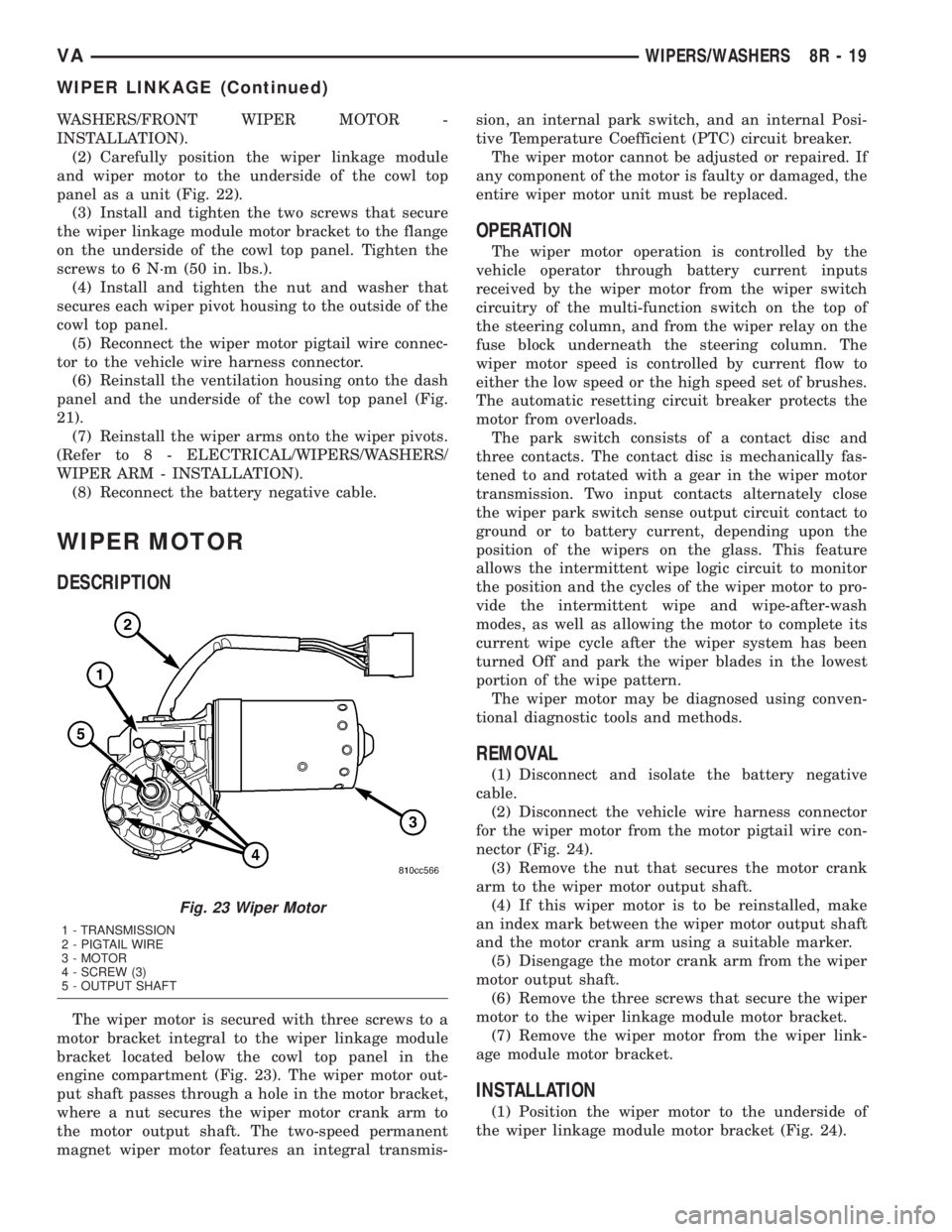
The wiper motor is secured with three screws to a
motor bracket integral to the wiper linkage module
bracket located below the cowl top panel in the
engine compartment (Fig. 23). The wiper motor out-
put shaft passes through a hole in the motor bracket,
where a nut secures the wiper motor crank arm to
the motor output shaft. The two-speed permanent
magnet wiper motor features an integral transmis-sion, an internal park switch, and an internal Posi-
tive Temperature Coefficient (PTC) circuit breaker.
The wiper motor cannot be adjusted or repaired. If
any component of the motor is faulty or damaged, the
entire wiper motor unit must be replaced.
OPERATION
The wiper motor operation is controlled by the
vehicle operator through battery current inputs
received by the wiper motor from the wiper switch
circuitry of the multi-function switch on the top of
the steering column, and from the wiper relay on the
fuse block underneath the steering column. The
wiper motor speed is controlled by current flow to
either the low speed or the high speed set of brushes.
The automatic resetting circuit breaker protects the
motor from overloads.
The park switch consists of a contact disc and
three contacts. The contact disc is mechanically fas-
tened to and rotated with a gear in the wiper motor
transmission. Two input contacts alternately close
the wiper park switch sense output circuit contact to
ground or to battery current, depending upon the
position of the wipers on the glass. This feature
allows the intermittent wipe logic circuit to monitor
the position and the cycles of the wiper motor to pro-
vide the intermittent wipe and wipe-after-wash
modes, as well as allowing the motor to complete its
current wipe cycle after the wiper system has been
turned Off and park the wiper blades in the lowest
portion of the wipe pattern.
The wiper motor may be diagnosed using conven-
tional diagnostic tools and methods.
REMOVAL
(1) Disconnect and isolate the battery negative
cable.
(2) Disconnect the vehicle wire harness connector
for the wiper motor from the motor pigtail wire con-
nector (Fig. 24).
(3) Remove the nut that secures the motor crank
arm to the wiper motor output shaft.
(4) If this wiper motor is to be reinstalled, make
an index mark between the wiper motor output shaft
and the motor crank arm using a suitable marker.
(5) Disengage the motor crank arm from the wiper
motor output shaft.
(6) Remove the three screws that secure the wiper
motor to the wiper linkage module motor bracket.
(7) Remove the wiper motor from the wiper link-
age module motor bracket.
INSTALLATION
(1) Position the wiper motor to the underside of
the wiper linkage module motor bracket (Fig. 24).
Fig. 23 Wiper Motor
1 - TRANSMISSION
2 - PIGTAIL WIRE
3 - MOTOR
4 - SCREW (3)
5 - OUTPUT SHAFT
VAWIPERS/WASHERS 8R - 19
WIPER LINKAGE (Continued)