2005 MERCEDES-BENZ SPRINTER engine
[x] Cancel search: enginePage 880 of 1232
SHIFT GROUPS
The hydraulic control components (including actua-
tors) which are responsible for the pressure distribu-
tion before, during, and after a gear change are
described as a shift group. Each shift group contains
a command valve, a holding pressure shift valve, a
shift pressure shift valve, overlap regulating valve,
and a solenoid.
The hydraulic system contains three shift groups:
1-2/4-5, 2-3, and 3-4. Each shift group can also be
described as being in one of two possible states. The
active shift group is described as being in the shift
phase when it is actively engaging/disengaging a
clutch combination. The 1-2/4-5 shift group control
the B1 and K1 clutches. The 2-3 shift group controls
the K2 and K3 clutches. The 3-4 shift group controls
the K3 and B2 clutches.
OPERATION
The transmission control is divided into the elec-
tronic and hydraulic transmission control functions.
While the electronic transmission control is responsi-
ble for gear selection and for matching the pressures
to the torque to be transmitted, the transmission's
power supply control occurs via hydraulic elements
in the electrohydraulic control module. The oil supply
to the hydraulic elements, such as the hydrodynamic
torque converter, the shift elements and the hydrau-
lic transmission control, is provided by way of an oil
pump connected with the torque converter.
The Transmission Control Module (TCM) allows for
the precise adaptation of pressures to the correspond-
ing operating conditions and to the engine output
during the gearshift phase, resulting in a noticeable
improvement in shift quality. The engine speed limit
can be reached in the individual gears at full throttle
and kickdown. The shift range can be changed in the
forward gears while driving, but the TCM employs adownshift safeguard to prevent over-revving the
engine. The system offers the additional advantage of
flexible adaptation to different vehicle and engine
variants.
EMERGENCY RUNNING FUNCTION
In order to ensure a safe driving state and to pre-
vent damage to the automatic transmission, the TCM
control module switches to limp-home mode in the
event of critical faults. A DTC assigned to the fault is
stored in memory. All solenoid and regulating valves
are thus de-energized.
The net effect is:
²The last engaged gear remains engaged.
²The modulating pressure and shift pressures
rise to the maximum levels.
²The torque converter lockup clutch is deacti-
vated.
In order to preserve the operability of the vehicle
to some extent, the hydraulic control can be used to
engage 2nd gear or reverse using the following pro-
cedure:
²Stop the vehicle.
²Switch off engine.
²Move selector lever to9P9.
²Wait at least 10 seconds.
²Start engine.
²Move selector lever to D: 2nd gear.
²Move selector lever to R: Reverse gear.
The limp-home function remains active until the
DTC is rectified or the stored DTC is erased with the
DRBttool. Sporadic faults can be reset via ignition
OFF/ON.
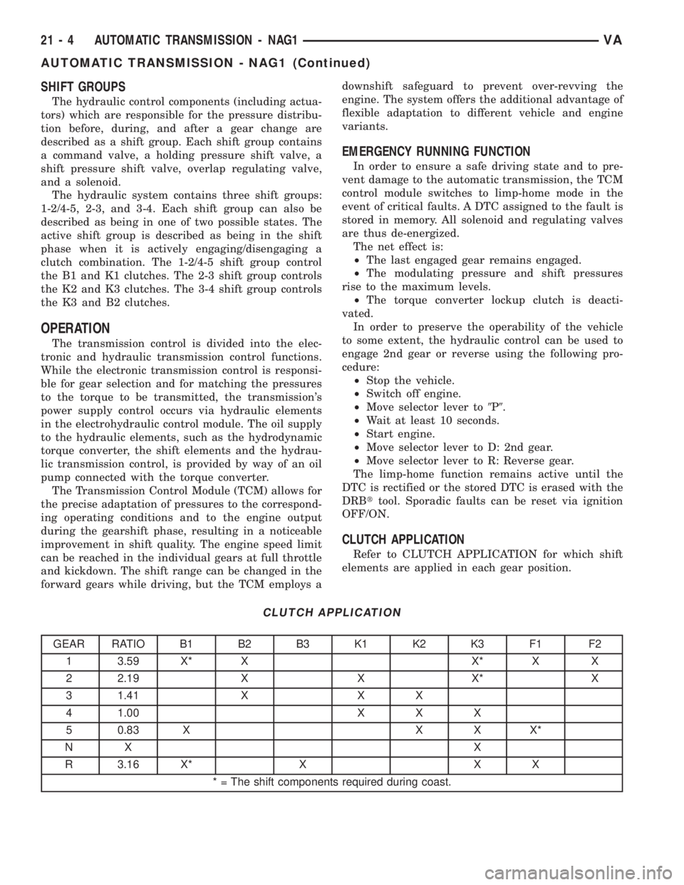
CLUTCH APPLICATION
Refer to CLUTCH APPLICATION for which shift
elements are applied in each gear position.
CLUTCH APPLICATION
GEAR RATIO B1 B2 B3 K1 K2 K3 F1 F2
1 3.59 X* X X* X X
2 2.19 X X X* X
3 1.41 X X X
4 1.00 X X X
5 0.83 X X X X*
NX X
R 3.16 X* X X X
* = The shift components required during coast.
21 - 4 AUTOMATIC TRANSMISSION - NAG1VA
AUTOMATIC TRANSMISSION - NAG1 (Continued)
Page 881 of 1232
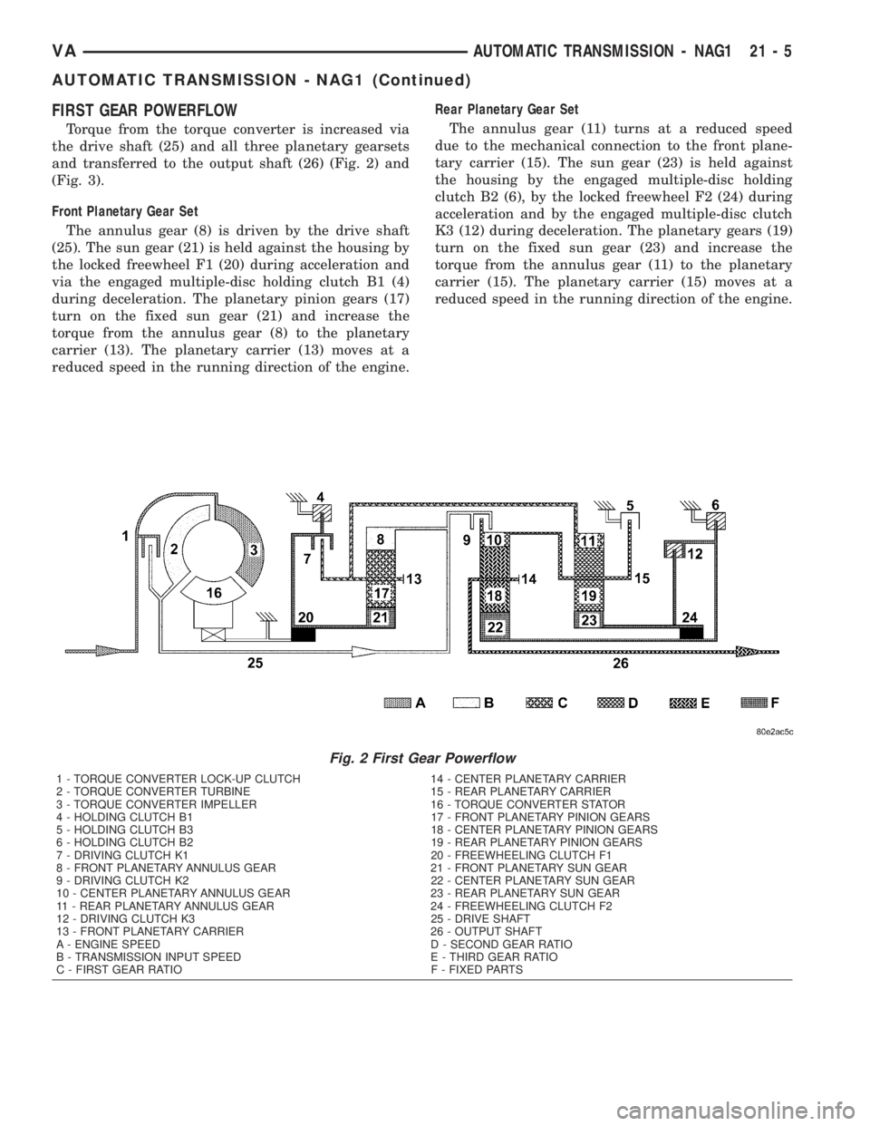
FIRST GEAR POWERFLOW
Torque from the torque converter is increased via
the drive shaft (25) and all three planetary gearsets
and transferred to the output shaft (26) (Fig. 2) and
(Fig. 3).
Front Planetary Gear Set
The annulus gear (8) is driven by the drive shaft
(25). The sun gear (21) is held against the housing by
the locked freewheel F1 (20) during acceleration and
via the engaged multiple-disc holding clutch B1 (4)
during deceleration. The planetary pinion gears (17)
turn on the fixed sun gear (21) and increase the
torque from the annulus gear (8) to the planetary
carrier (13). The planetary carrier (13) moves at a
reduced speed in the running direction of the engine.Rear Planetary Gear Set
The annulus gear (11) turns at a reduced speed
due to the mechanical connection to the front plane-
tary carrier (15). The sun gear (23) is held against
the housing by the engaged multiple-disc holding
clutch B2 (6), by the locked freewheel F2 (24) during
acceleration and by the engaged multiple-disc clutch
K3 (12) during deceleration. The planetary gears (19)
turn on the fixed sun gear (23) and increase the
torque from the annulus gear (11) to the planetary
carrier (15). The planetary carrier (15) moves at a
reduced speed in the running direction of the engine.
Fig. 2 First Gear Powerflow
1 - TORQUE CONVERTER LOCK-UP CLUTCH 14 - CENTER PLANETARY CARRIER
2 - TORQUE CONVERTER TURBINE 15 - REAR PLANETARY CARRIER
3 - TORQUE CONVERTER IMPELLER 16 - TORQUE CONVERTER STATOR
4 - HOLDING CLUTCH B1 17 - FRONT PLANETARY PINION GEARS
5 - HOLDING CLUTCH B3 18 - CENTER PLANETARY PINION GEARS
6 - HOLDING CLUTCH B2 19 - REAR PLANETARY PINION GEARS
7 - DRIVING CLUTCH K1 20 - FREEWHEELING CLUTCH F1
8 - FRONT PLANETARY ANNULUS GEAR 21 - FRONT PLANETARY SUN GEAR
9 - DRIVING CLUTCH K2 22 - CENTER PLANETARY SUN GEAR
10 - CENTER PLANETARY ANNULUS GEAR 23 - REAR PLANETARY SUN GEAR
11 - REAR PLANETARY ANNULUS GEAR 24 - FREEWHEELING CLUTCH F2
12 - DRIVING CLUTCH K3 25 - DRIVE SHAFT
13 - FRONT PLANETARY CARRIER 26 - OUTPUT SHAFT
A - ENGINE SPEED D - SECOND GEAR RATIO
B - TRANSMISSION INPUT SPEED E - THIRD GEAR RATIO
C - FIRST GEAR RATIO F - FIXED PARTS
VAAUTOMATIC TRANSMISSION - NAG1 21 - 5
AUTOMATIC TRANSMISSION - NAG1 (Continued)
Page 882 of 1232
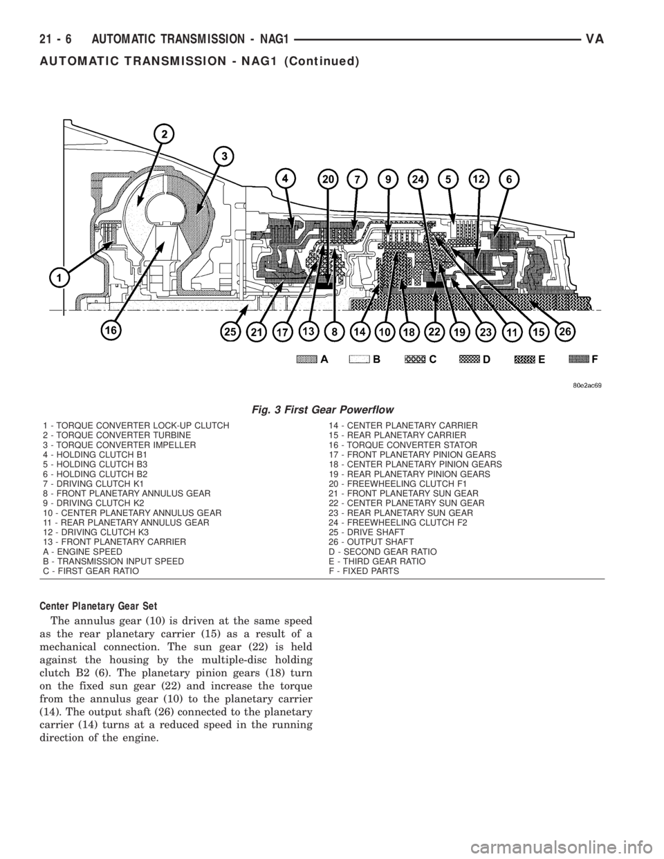
Center Planetary Gear Set
The annulus gear (10) is driven at the same speed
as the rear planetary carrier (15) as a result of a
mechanical connection. The sun gear (22) is held
against the housing by the multiple-disc holding
clutch B2 (6). The planetary pinion gears (18) turn
on the fixed sun gear (22) and increase the torque
from the annulus gear (10) to the planetary carrier
(14). The output shaft (26) connected to the planetary
carrier (14) turns at a reduced speed in the running
direction of the engine.
Fig. 3 First Gear Powerflow
1 - TORQUE CONVERTER LOCK-UP CLUTCH 14 - CENTER PLANETARY CARRIER
2 - TORQUE CONVERTER TURBINE 15 - REAR PLANETARY CARRIER
3 - TORQUE CONVERTER IMPELLER 16 - TORQUE CONVERTER STATOR
4 - HOLDING CLUTCH B1 17 - FRONT PLANETARY PINION GEARS
5 - HOLDING CLUTCH B3 18 - CENTER PLANETARY PINION GEARS
6 - HOLDING CLUTCH B2 19 - REAR PLANETARY PINION GEARS
7 - DRIVING CLUTCH K1 20 - FREEWHEELING CLUTCH F1
8 - FRONT PLANETARY ANNULUS GEAR 21 - FRONT PLANETARY SUN GEAR
9 - DRIVING CLUTCH K2 22 - CENTER PLANETARY SUN GEAR
10 - CENTER PLANETARY ANNULUS GEAR 23 - REAR PLANETARY SUN GEAR
11 - REAR PLANETARY ANNULUS GEAR 24 - FREEWHEELING CLUTCH F2
12 - DRIVING CLUTCH K3 25 - DRIVE SHAFT
13 - FRONT PLANETARY CARRIER 26 - OUTPUT SHAFT
A - ENGINE SPEED D - SECOND GEAR RATIO
B - TRANSMISSION INPUT SPEED E - THIRD GEAR RATIO
C - FIRST GEAR RATIO F - FIXED PARTS
21 - 6 AUTOMATIC TRANSMISSION - NAG1VA
AUTOMATIC TRANSMISSION - NAG1 (Continued)
Page 883 of 1232
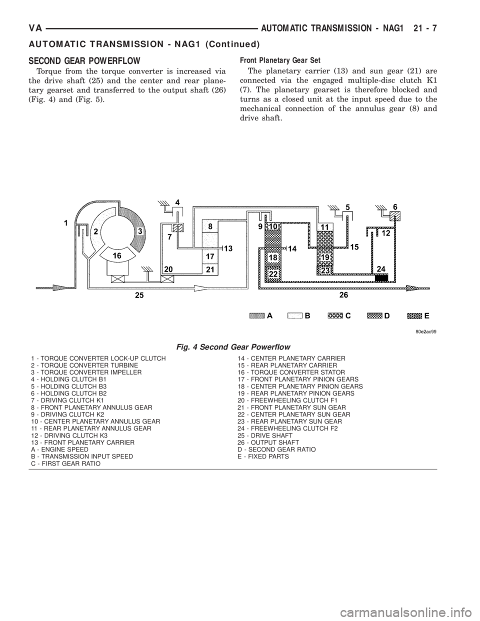
SECOND GEAR POWERFLOW
Torque from the torque converter is increased via
the drive shaft (25) and the center and rear plane-
tary gearset and transferred to the output shaft (26)
(Fig. 4) and (Fig. 5).Front Planetary Gear Set
The planetary carrier (13) and sun gear (21) are
connected via the engaged multiple-disc clutch K1
(7). The planetary gearset is therefore blocked and
turns as a closed unit at the input speed due to the
mechanical connection of the annulus gear (8) and
drive shaft.
Fig. 4 Second Gear Powerflow
1 - TORQUE CONVERTER LOCK-UP CLUTCH 14 - CENTER PLANETARY CARRIER
2 - TORQUE CONVERTER TURBINE 15 - REAR PLANETARY CARRIER
3 - TORQUE CONVERTER IMPELLER 16 - TORQUE CONVERTER STATOR
4 - HOLDING CLUTCH B1 17 - FRONT PLANETARY PINION GEARS
5 - HOLDING CLUTCH B3 18 - CENTER PLANETARY PINION GEARS
6 - HOLDING CLUTCH B2 19 - REAR PLANETARY PINION GEARS
7 - DRIVING CLUTCH K1 20 - FREEWHEELING CLUTCH F1
8 - FRONT PLANETARY ANNULUS GEAR 21 - FRONT PLANETARY SUN GEAR
9 - DRIVING CLUTCH K2 22 - CENTER PLANETARY SUN GEAR
10 - CENTER PLANETARY ANNULUS GEAR 23 - REAR PLANETARY SUN GEAR
11 - REAR PLANETARY ANNULUS GEAR 24 - FREEWHEELING CLUTCH F2
12 - DRIVING CLUTCH K3 25 - DRIVE SHAFT
13 - FRONT PLANETARY CARRIER 26 - OUTPUT SHAFT
A - ENGINE SPEED D - SECOND GEAR RATIO
B - TRANSMISSION INPUT SPEED E - FIXED PARTS
C - FIRST GEAR RATIO
VAAUTOMATIC TRANSMISSION - NAG1 21 - 7
AUTOMATIC TRANSMISSION - NAG1 (Continued)
Page 884 of 1232
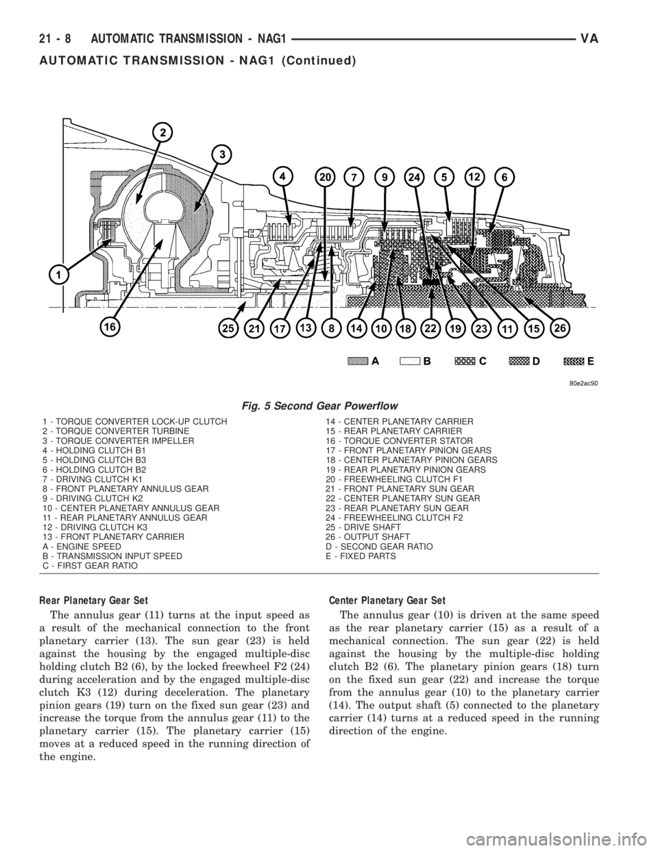
Rear Planetary Gear Set
The annulus gear (11) turns at the input speed as
a result of the mechanical connection to the front
planetary carrier (13). The sun gear (23) is held
against the housing by the engaged multiple-disc
holding clutch B2 (6), by the locked freewheel F2 (24)
during acceleration and by the engaged multiple-disc
clutch K3 (12) during deceleration. The planetary
pinion gears (19) turn on the fixed sun gear (23) and
increase the torque from the annulus gear (11) to the
planetary carrier (15). The planetary carrier (15)
moves at a reduced speed in the running direction of
the engine.Center Planetary Gear Set
The annulus gear (10) is driven at the same speed
as the rear planetary carrier (15) as a result of a
mechanical connection. The sun gear (22) is held
against the housing by the multiple-disc holding
clutch B2 (6). The planetary pinion gears (18) turn
on the fixed sun gear (22) and increase the torque
from the annulus gear (10) to the planetary carrier
(14). The output shaft (5) connected to the planetary
carrier (14) turns at a reduced speed in the running
direction of the engine.
Fig. 5 Second Gear Powerflow
1 - TORQUE CONVERTER LOCK-UP CLUTCH 14 - CENTER PLANETARY CARRIER
2 - TORQUE CONVERTER TURBINE 15 - REAR PLANETARY CARRIER
3 - TORQUE CONVERTER IMPELLER 16 - TORQUE CONVERTER STATOR
4 - HOLDING CLUTCH B1 17 - FRONT PLANETARY PINION GEARS
5 - HOLDING CLUTCH B3 18 - CENTER PLANETARY PINION GEARS
6 - HOLDING CLUTCH B2 19 - REAR PLANETARY PINION GEARS
7 - DRIVING CLUTCH K1 20 - FREEWHEELING CLUTCH F1
8 - FRONT PLANETARY ANNULUS GEAR 21 - FRONT PLANETARY SUN GEAR
9 - DRIVING CLUTCH K2 22 - CENTER PLANETARY SUN GEAR
10 - CENTER PLANETARY ANNULUS GEAR 23 - REAR PLANETARY SUN GEAR
11 - REAR PLANETARY ANNULUS GEAR 24 - FREEWHEELING CLUTCH F2
12 - DRIVING CLUTCH K3 25 - DRIVE SHAFT
13 - FRONT PLANETARY CARRIER 26 - OUTPUT SHAFT
A - ENGINE SPEED D - SECOND GEAR RATIO
B - TRANSMISSION INPUT SPEED E - FIXED PARTS
C - FIRST GEAR RATIO
21 - 8 AUTOMATIC TRANSMISSION - NAG1VA
AUTOMATIC TRANSMISSION - NAG1 (Continued)
Page 885 of 1232
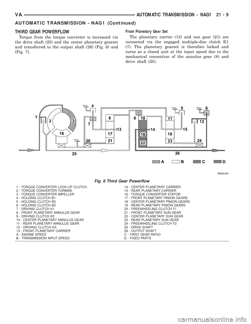
THIRD GEAR POWERFLOW
Torque from the torque converter is increased via
the drive shaft (25) and the center planetary gearset
and transferred to the output shaft (26) (Fig. 6) and
(Fig. 7).Front Planetary Gear Set
The planetary carrier (13) and sun gear (21) are
connected via the engaged multiple-disc clutch K1
(7). The planetary gearset is therefore locked and
turns as a closed unit at the input speed due to the
mechanical connection of the annulus gear (8) and
drive shaft (25).
Fig. 6 Third Gear Powerflow
1 - TORQUE CONVERTER LOCK-UP CLUTCH 14 - CENTER PLANETARY CARRIER
2 - TORQUE CONVERTER TURBINE 15 - REAR PLANETARY CARRIER
3 - TORQUE CONVERTER IMPELLER 16 - TORQUE CONVERTER STATOR
4 - HOLDING CLUTCH B1 17 - FRONT PLANETARY PINION GEARS
5 - HOLDING CLUTCH B3 18 - CENTER PLANETARY PINION GEARS
6 - HOLDING CLUTCH B2 19 - REAR PLANETARY PINION GEARS
7 - DRIVING CLUTCH K1 20 - FREEWHEELING CLUTCH F1
8 - FRONT PLANETARY ANNULUS GEAR 21 - FRONT PLANETARY SUN GEAR
9 - DRIVING CLUTCH K2 22 - CENTER PLANETARY SUN GEAR
10 - CENTER PLANETARY ANNULUS GEAR 23 - REAR PLANETARY SUN GEAR
11 - REAR PLANETARY ANNULUS GEAR 24 - FREEWHEELING CLUTCH F2
12 - DRIVING CLUTCH K3 25 - DRIVE SHAFT
13 - FRONT PLANETARY CARRIER 26 - OUTPUT SHAFT
A - ENGINE SPEED C - FIRST GEAR RATIO
B - TRANSMISSION INPUT SPEED D - FIXED PARTS
VAAUTOMATIC TRANSMISSION - NAG1 21 - 9
AUTOMATIC TRANSMISSION - NAG1 (Continued)
Page 886 of 1232
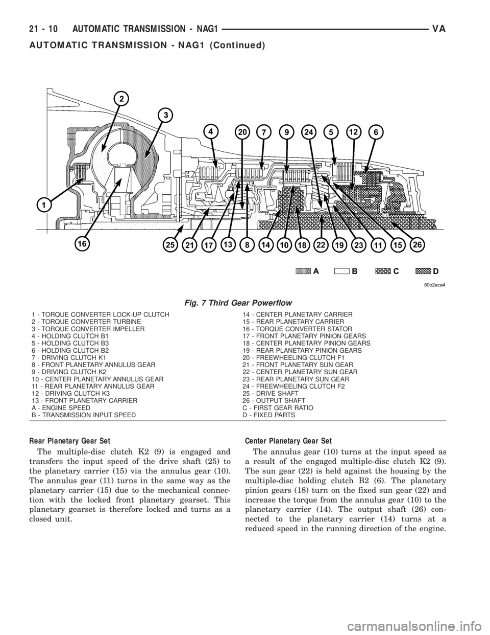
Rear Planetary Gear Set
The multiple-disc clutch K2 (9) is engaged and
transfers the input speed of the drive shaft (25) to
the planetary carrier (15) via the annulus gear (10).
The annulus gear (11) turns in the same way as the
planetary carrier (15) due to the mechanical connec-
tion with the locked front planetary gearset. This
planetary gearset is therefore locked and turns as a
closed unit.Center Planetary Gear Set
The annulus gear (10) turns at the input speed as
a result of the engaged multiple-disc clutch K2 (9).
The sun gear (22) is held against the housing by the
multiple-disc holding clutch B2 (6). The planetary
pinion gears (18) turn on the fixed sun gear (22) and
increase the torque from the annulus gear (10) to the
planetary carrier (14). The output shaft (26) con-
nected to the planetary carrier (14) turns at a
reduced speed in the running direction of the engine.
Fig. 7 Third Gear Powerflow
1 - TORQUE CONVERTER LOCK-UP CLUTCH 14 - CENTER PLANETARY CARRIER
2 - TORQUE CONVERTER TURBINE 15 - REAR PLANETARY CARRIER
3 - TORQUE CONVERTER IMPELLER 16 - TORQUE CONVERTER STATOR
4 - HOLDING CLUTCH B1 17 - FRONT PLANETARY PINION GEARS
5 - HOLDING CLUTCH B3 18 - CENTER PLANETARY PINION GEARS
6 - HOLDING CLUTCH B2 19 - REAR PLANETARY PINION GEARS
7 - DRIVING CLUTCH K1 20 - FREEWHEELING CLUTCH F1
8 - FRONT PLANETARY ANNULUS GEAR 21 - FRONT PLANETARY SUN GEAR
9 - DRIVING CLUTCH K2 22 - CENTER PLANETARY SUN GEAR
10 - CENTER PLANETARY ANNULUS GEAR 23 - REAR PLANETARY SUN GEAR
11 - REAR PLANETARY ANNULUS GEAR 24 - FREEWHEELING CLUTCH F2
12 - DRIVING CLUTCH K3 25 - DRIVE SHAFT
13 - FRONT PLANETARY CARRIER 26 - OUTPUT SHAFT
A - ENGINE SPEED C - FIRST GEAR RATIO
B - TRANSMISSION INPUT SPEED D - FIXED PARTS
21 - 10 AUTOMATIC TRANSMISSION - NAG1VA
AUTOMATIC TRANSMISSION - NAG1 (Continued)
Page 887 of 1232
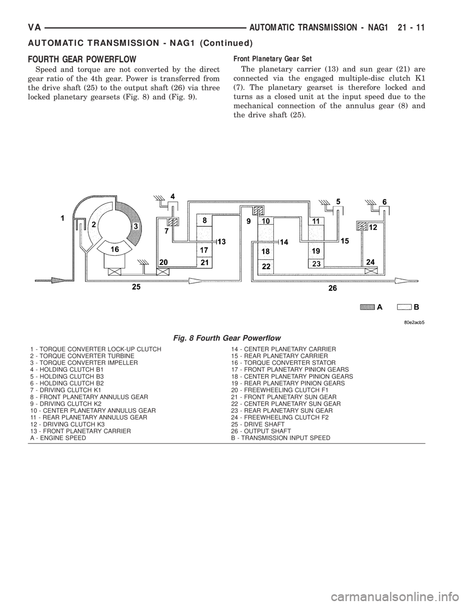
FOURTH GEAR POWERFLOW
Speed and torque are not converted by the direct
gear ratio of the 4th gear. Power is transferred from
the drive shaft (25) to the output shaft (26) via three
locked planetary gearsets (Fig. 8) and (Fig. 9).Front Planetary Gear Set
The planetary carrier (13) and sun gear (21) are
connected via the engaged multiple-disc clutch K1
(7). The planetary gearset is therefore locked and
turns as a closed unit at the input speed due to the
mechanical connection of the annulus gear (8) and
the drive shaft (25).
Fig. 8 Fourth Gear Powerflow
1 - TORQUE CONVERTER LOCK-UP CLUTCH 14 - CENTER PLANETARY CARRIER
2 - TORQUE CONVERTER TURBINE 15 - REAR PLANETARY CARRIER
3 - TORQUE CONVERTER IMPELLER 16 - TORQUE CONVERTER STATOR
4 - HOLDING CLUTCH B1 17 - FRONT PLANETARY PINION GEARS
5 - HOLDING CLUTCH B3 18 - CENTER PLANETARY PINION GEARS
6 - HOLDING CLUTCH B2 19 - REAR PLANETARY PINION GEARS
7 - DRIVING CLUTCH K1 20 - FREEWHEELING CLUTCH F1
8 - FRONT PLANETARY ANNULUS GEAR 21 - FRONT PLANETARY SUN GEAR
9 - DRIVING CLUTCH K2 22 - CENTER PLANETARY SUN GEAR
10 - CENTER PLANETARY ANNULUS GEAR 23 - REAR PLANETARY SUN GEAR
11 - REAR PLANETARY ANNULUS GEAR 24 - FREEWHEELING CLUTCH F2
12 - DRIVING CLUTCH K3 25 - DRIVE SHAFT
13 - FRONT PLANETARY CARRIER 26 - OUTPUT SHAFT
A - ENGINE SPEED B - TRANSMISSION INPUT SPEED
VAAUTOMATIC TRANSMISSION - NAG1 21 - 11
AUTOMATIC TRANSMISSION - NAG1 (Continued)