2005 MERCEDES-BENZ SPRINTER engine
[x] Cancel search: enginePage 845 of 1232
FUEL INJECTION
TABLE OF CONTENTS
page page
ACCELERATOR PEDAL POSITION SENSOR
DESCRIPTION.........................17
BOOST PRESSURE SENSOR
DESCRIPTION.........................17
OPERATION...........................18
DIAGNOSIS AND TESTING - BOOST
PRESSURE SENSOR..................18
REMOVAL.............................18
INSTALLATION.........................18
CAMSHAFT POSITION SENSOR
DESCRIPTION.........................19
OPERATION...........................19
REMOVAL.............................19
INSTALLATION.........................19
CRANKSHAFT POSITION SENSOR
DESCRIPTION.........................20
OPERATION...........................20
REMOVAL.............................20
INSTALLATION.........................20
FUEL INJECTOR
DESCRIPTION
FUEL INJECTOR......................20
OPERATION...........................20
STANDARD PROCEDURE
STANDARD PROCEDURE - INJECTOR
CLASSIFICATION.....................22
STANDARD PROCEDURE - CLEANING
FUEL INJECTORS.....................22
REMOVAL.............................23
INSTALLATION.........................23
FUEL PRESSURE SENSOR
DESCRIPTION
DESCRIPTION........................25DESCRIPTION........................25
OPERATION
OPERATION.........................25
OPERATION.........................25
REMOVAL
REMOVAL...........................26
REMOVAL...........................26
INSTALLATION
INSTALLATION.......................26
INSTALLATION.......................27
FUEL PRESSURE SOLENOID
DESCRIPTION.........................27
OPERATION...........................27
REMOVAL.............................28
INSTALLATION.........................28
FUEL TEMPERATURE SENSOR
DESCRIPTION.........................29
OPERATION...........................29
REMOVAL.............................29
INSTALLATION.........................29
INLET AIR TEMPERATURE SENSOR
DESCRIPTION.........................29
OPERATION...........................29
REMOVAL.............................30
INSTALLATION.........................30
MANIFOLD AIR FLOW (MAF) SENSOR
DESCRIPTION.........................30
OPERATION...........................30
REMOVAL.............................31
INSTALLATION.........................31
ACCELERATOR PEDAL
POSITION SENSOR
DESCRIPTION
The accelerator pedal position sensor is located on
the accelerator pedal assembly. The driver supplies
the torque requirements for the engine by operating
the accelerator pedal in accordance with the desired
speed or acceleration. The pedal sensor converts the
mechanical operation of the pedal into an electrical
signal and sends the information to the ECM. The
ECM adjusts the quantity of the fuel that is injected
into the engine (Fig. 1).The accelerator pedal position sensor is serviced as
an assembly with the accelerator assembly.
BOOST PRESSURE SENSOR
DESCRIPTION
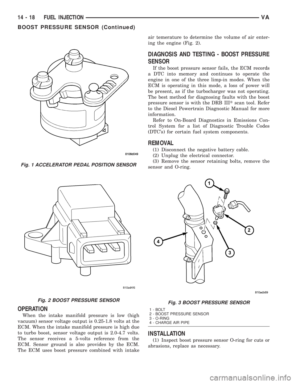
The boost pressure sensor is mounted to the charge
air pipe (Fig. 2). The sensor allows the ECM to mon-
itor intake air down stream of the turbocharger.
VAFUEL INJECTION 14 - 17
Page 846 of 1232
OPERATION
When the intake manifold pressure is low (high
vacuum) sensor voltage output is 0.25-1.8 volts at the
ECM. When the intake manifold pressure is high due
to turbo boost, sensor voltage output is 2.0-4.7 volts.
The sensor receives a 5-volts reference from the
ECM. Sensor ground is also provides by the ECM.
The ECM uses boost pressure combined with intakeair temerature to determine the volume of air enter-
ing the engine (Fig. 2).
DIAGNOSIS AND TESTING - BOOST PRESSURE
SENSOR
If the boost pressure sensor fails, the ECM records
a DTC into memory and continues to operate the
engine in one of the three limp-in modes. When the
ECM is operating in this mode, a loss of power will
be present, as if the turbocharger was not operating.
The best method for diagnosing faults with the boost
pressure sensor is with the DRB IIItscan tool. Refer
to the Diesel Powertrain Diagnostic Manual for more
information.
Refer to On-Board Diagnostics in Emissions Con-
trol System for a list of Diagnostic Trouble Codes
(DTC's) for certain fuel system components.
REMOVAL
(1) Disconnect the negative battery cable.
(2) Unplug the electrical connector.
(3) Remove the sensor retaining bolts, remove the
sensor and O-ring.
INSTALLATION
(1) Inspect boost pressure sensor O-ring for cuts or
abrasions, replace as necessary.
Fig. 1 ACCELERATOR PEDAL POSITION SENSOR
Fig. 2 BOOST PRESSURE SENSORFig. 3 BOOST PRESSURE SENSOR
1 - BOLT
2 - BOOST PRESSURE SENSOR
3 - O-RING
4 - CHARGE AIR PIPE
14 - 18 FUEL INJECTIONVA
BOOST PRESSURE SENSOR (Continued)
Page 847 of 1232
(2) Position the boost pressure sensor above access
hole in the charge air pipe and push down to fit flush
(Fig. 3).
(3) Install the bolts and tighten to 44 lbs. in. (5
N´m) (Fig. 3).
(4) Reconnect the sensor electrical connector (Fig.
3).
(5) Connect negative battery cable
CAMSHAFT POSITION
SENSOR
DESCRIPTION
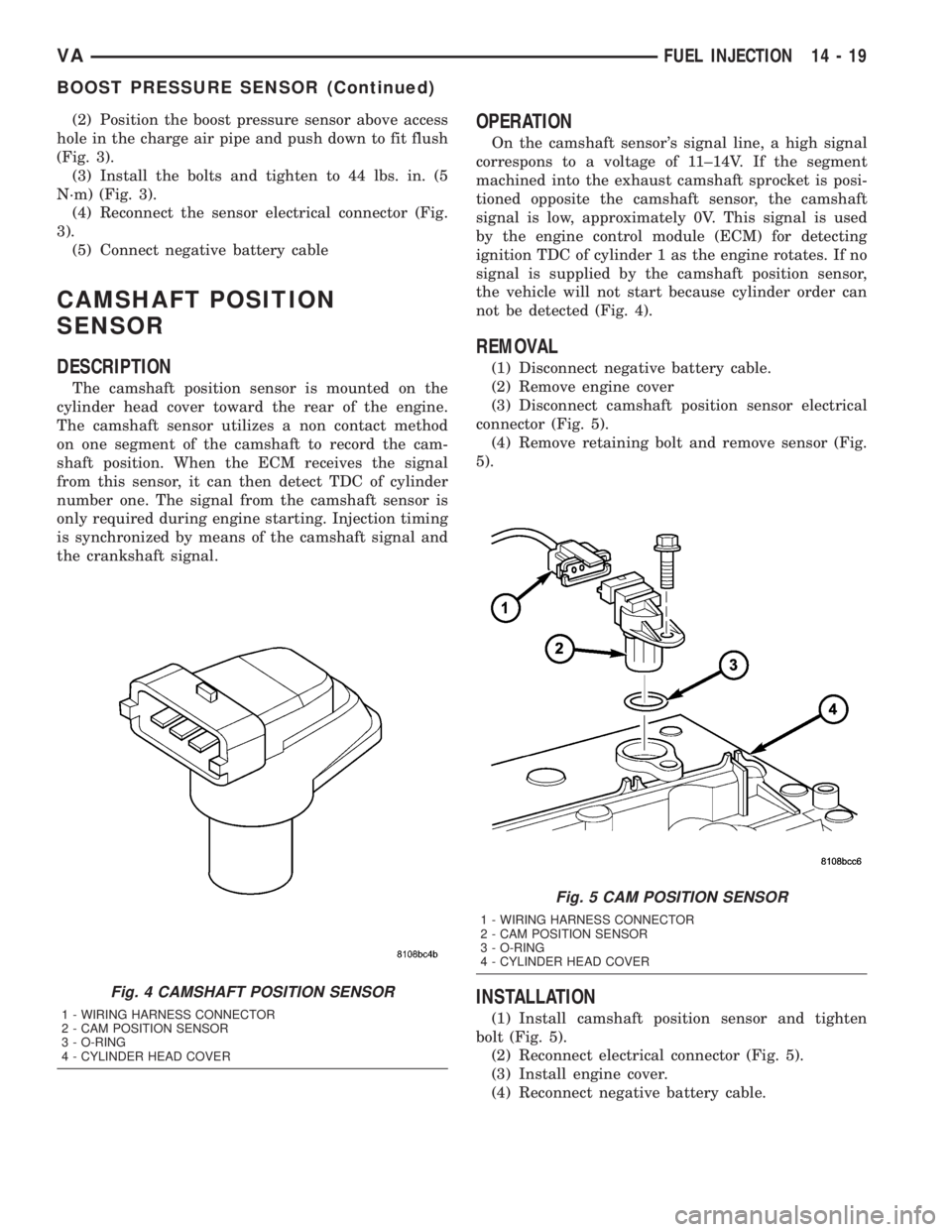
The camshaft position sensor is mounted on the
cylinder head cover toward the rear of the engine.
The camshaft sensor utilizes a non contact method
on one segment of the camshaft to record the cam-
shaft position. When the ECM receives the signal
from this sensor, it can then detect TDC of cylinder
number one. The signal from the camshaft sensor is
only required during engine starting. Injection timing
is synchronized by means of the camshaft signal and
the crankshaft signal.
OPERATION
On the camshaft sensor's signal line, a high signal
correspons to a voltage of 11±14V. If the segment
machined into the exhaust camshaft sprocket is posi-
tioned opposite the camshaft sensor, the camshaft
signal is low, approximately 0V. This signal is used
by the engine control module (ECM) for detecting
ignition TDC of cylinder 1 as the engine rotates. If no
signal is supplied by the camshaft position sensor,
the vehicle will not start because cylinder order can
not be detected (Fig. 4).
REMOVAL
(1) Disconnect negative battery cable.
(2) Remove engine cover
(3) Disconnect camshaft position sensor electrical
connector (Fig. 5).
(4) Remove retaining bolt and remove sensor (Fig.
5).
INSTALLATION
(1) Install camshaft position sensor and tighten
bolt (Fig. 5).
(2) Reconnect electrical connector (Fig. 5).
(3) Install engine cover.
(4) Reconnect negative battery cable.
Fig. 4 CAMSHAFT POSITION SENSOR
1 - WIRING HARNESS CONNECTOR
2 - CAM POSITION SENSOR
3 - O-RING
4 - CYLINDER HEAD COVER
Fig. 5 CAM POSITION SENSOR
1 - WIRING HARNESS CONNECTOR
2 - CAM POSITION SENSOR
3 - O-RING
4 - CYLINDER HEAD COVER
VAFUEL INJECTION 14 - 19
BOOST PRESSURE SENSOR (Continued)
Page 848 of 1232
CRANKSHAFT POSITION
SENSOR
DESCRIPTION
The crankshaft position sensor is located opposite
the teeth on the flywheel and uses a non contact
method to record the position of the crankshaft. The
leading edges of each tooth on the flywheel generate
a positive signal in the position sensor, while the
trailing edges generate a negative signal. When the
crankshaft is rotating, an alternating voltage is pro-
duced as a result.
The period of the signal is the time required by the
crankshaft to turn through the gap between two fly-
wheel teeth. The clearance between the crankshaft
position sensor and the teeth of the flywheel is fixed
by the installation.
Two teeth on the flywheel are missing. The result-
ing signal gap is used by the ECM to detect the TDC
position of cylinder number one.
OPERATION
The clearance between the crankshaft position sen-
sor and the flywheel are fixed by the installation
position. Two teeth on the flywheel are missing. The
resulting gap is used by the ECM to detect DTC of
cylinder number one. The crankshaft position is cal-
culated to an accuracy of a fraction of a degree so
that the start and end of injection can occur at
exactly the right moment. The engine speed signal is
also processed by the ECM from the crankshaft sen-
sor. This signal is then transferred to other control
modules over the CAN bus.
If the crankshaft position sensor fails, the signal
that provides reference rotation is missing. Injection
may occur at the wrong time and damage the engine.
In this case, the ECM will stop triggering the injec-
tors, the engine would cut out, the engine warning
light would illuminate and the engine will not
restart.
REMOVAL
(1) Disconnect the negative battery cable.
(2) Unplug the crankshaft wiring harness connec-
tor.
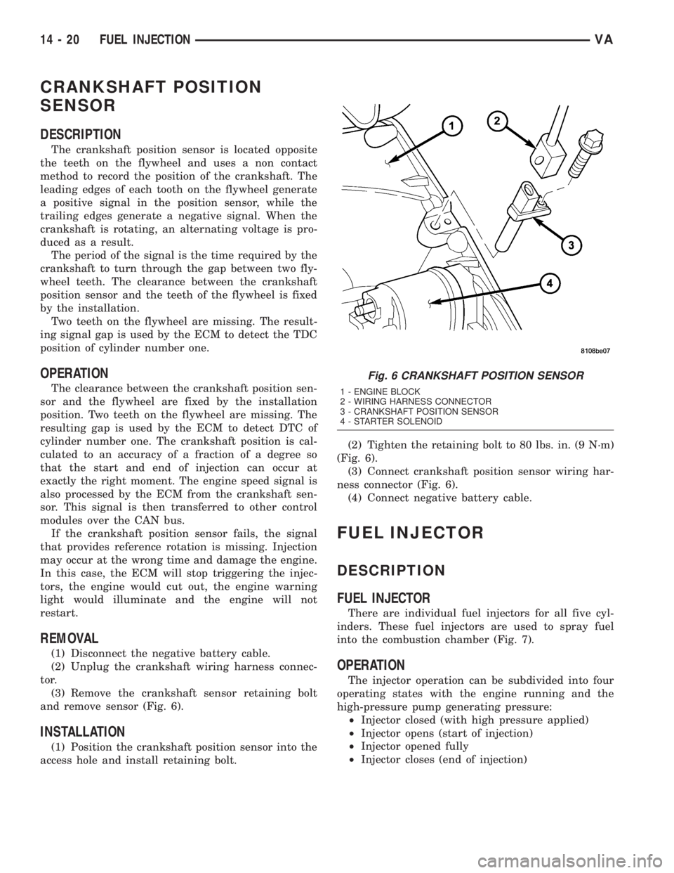
(3) Remove the crankshaft sensor retaining bolt
and remove sensor (Fig. 6).
INSTALLATION
(1) Position the crankshaft position sensor into the
access hole and install retaining bolt.(2) Tighten the retaining bolt to 80 lbs. in. (9 N´m)
(Fig. 6).
(3) Connect crankshaft position sensor wiring har-
ness connector (Fig. 6).
(4) Connect negative battery cable.
FUEL INJECTOR
DESCRIPTION
FUEL INJECTOR
There are individual fuel injectors for all five cyl-
inders. These fuel injectors are used to spray fuel
into the combustion chamber (Fig. 7).
OPERATION
The injector operation can be subdivided into four
operating states with the engine running and the
high-pressure pump generating pressure:
²Injector closed (with high pressure applied)
²Injector opens (start of injection)
²Injector opened fully
²Injector closes (end of injection)
Fig. 6 CRANKSHAFT POSITION SENSOR
1 - ENGINE BLOCK
2 - WIRING HARNESS CONNECTOR
3 - CRANKSHAFT POSITION SENSOR
4 - STARTER SOLENOID
14 - 20 FUEL INJECTIONVA
Page 850 of 1232
Injector opens fully
The control plunger reaches its upper stop where it
remains supported by a cushion of fuel which is gen-
erated by the flow of fuel between the bleed and feed
orifices. The injector nozzle has now opened fully,
and the fuel is injected into the combustion chamber
at a pressure almost equal to that in the fuel rail
(Fig. 8).
Injector closes (end of injection)
As soon as the solenoid valve is no longer trig-
gered, the valve spring forces the armature down-
wards and the ball closes the bleed orifice. The
armature is a 2±piece design. Here, although the
armature plate is guided by a driver shoulder in its
downward movement, it can ªoverspringº with the
return spring so that it exerts no downwards-acting
forces on the armature and the ball. The closing of
the bleed orifice lead to pressure build up in the con-
trol chamber via the input from the feed orifice. This
pressure is the same as that in the rail and exerts an
increased force on the control plunger through its
end face. This force, together with that of the spring,
now exceeds the force exerted by the chamber volume
and the nozzle needle closes. Injection ceases as soon
as the nozzle needle comes up against its bottom stop
again (Fig. 8).
STANDARD PROCEDURE
STANDARD PROCEDURE - INJECTOR
CLASSIFICATION
The classification of injectors into 3 classes
describes the quantity characteristic of the injector.
This will make it possible in the future to match the
engine software to the tolerances of the injector
within a more narrowly graduated range. Classifica-
tion can be clearly recognized, and assigned only by
means of a DRBIIIt.
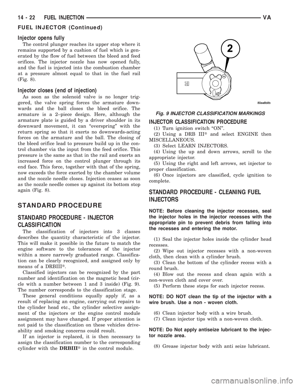
Classified injectors can be recognized by the part
number and identification on the magnetic head (cir-
cle with a number between 1 and 3 inside) (Fig. 9).
The number corresponds to the classification stage.
These general conditions equally apply if, as a
result of replacing an engine, carrying out repairs to
the cylinder head etc., the cylinder selective assign-
ment of the injectors or the engine control module
assignment may have changed. If proper attention is
not paid to the classification on these vehicles drive-
ability and smoking concerns could result.
If an injector is replaced, it is then necessary to
assign the classification number to the corresponding
cylinder with theDRBIIItin the control module.
INJECTOR CLASSIFICATION PROCEDURE
(1) Turn ignition switch ªONº.
(2) Using a DRB IIItand select ENGINE then
MISCELLANEOUS.
(3) Select LEARN INJECTORS.
(4) Using the up and down arrows, scroll to the
appropriate injector.
(5) Using the right and left arrows, set injector to
proper classification.
(6) Once injectors are classified, cycle ignition to
complete.
STANDARD PROCEDURE - CLEANING FUEL
INJECTORS
NOTE: Before cleaning the injector recesses, seal
the injector holes in the injector recesses with the
appropriate pin to prevent debris from falling into
the recesses and entering the motor.
(1) Seal the injector holes inside the cylinder head
recesses.
(2) Wipe out injector recesses with a non-woven
cloth, then clean with a cylinder brush.
(3) Clean the bottom of the cylinder recess with a
round brush.
(4) Blow out the recess and clean again with a
non-woven cloth and cover over.
(5) Perform these steps for each injector recess.
NOTE: DO NOT clean the tip of the injector with a
wire brush. Use a non - woven cloth.
(6) Clean injector body with a wire brush.
(7) Clean injector tips with a non-woven cloth.
NOTE: Do Not apply antiseize lubricant to the injec-
tor nozzle area.
(8) Grease injector body with anti seize lubricant.
Fig. 9 INJECTOR CLASSIFICATION MARKINGS
14 - 22 FUEL INJECTIONVA
FUEL INJECTOR (Continued)
Page 851 of 1232
NOTE: Always replace the seals that seal off the
injectors at the cylinder head to the combustion
chamber and replace the retaining screws.
REMOVAL
WARNING: HIGH-PRESSURE FUEL LINES DELIVER
DIESEL FUEL UNDER EXTREME PRESSURE FROM
THE INJECTION PUMP TO THE FUEL INJECTORS.
THIS MAY BE AS HIGH AS 1600BAR (23,200 PSI).
USE EXTREME CAUTION WHEN INSPECTING FOR
HIGH-PRESSURE FUEL LEAKS. FUEL UNDER THIS
AMOUNT OF PRESSURE CAN PENETRATE SKIN
CAUSING PERSONAL INJURY OR DEATH. INSPECT
FOR HIGH-PRESSURE LEAKS WITH A SHEET OF
CARD BOARD. WEAR SAFETY GOGGLES AND
ADEQUATE PROTECTIVE CLOTHING WHEN SER-
VICING FUEL SYSTEM.
WARNING: NO SPARKS, OPEN FLAMES OR SMOK-
ING. RISK OF POISONING FROM INHALING AND
SWALLOWING FUEL. RISK OF INJURY TO EYES
AND SKIN FROM CONTACT WITH FUEL. POUR
FUELS ONLY INTO SUITABLE AND APPROPRI-
ATELY MARKED CONTAINERS. WEAR PROTECTIVE
CLOTHING.
NOTE: The engine must be lowered in the vehicle to
remove the fourth and fifth cylinders fuel injectors.
(1) Disconnect negative battery cable.
(2) Remove engine cover (Refer to 9 - ENGINE -
REMOVAL).
(3) Raise and suitably support the vehicle.
(4) Remove lower radiator deflector plate.
(5) Drain cooling system (Refer to 7 - COOLING/
ENGINE/COOLANT - STANDARD PROCEDURE).
(6) Remove turbocharger down pipe assembly.
(7) Remove oil dipstick tube retaining bolt and pull
tube from oil pan.
(8) Lower vehicle.
(9) Remove upper radiator hose.
(10) Remove air cleaner box assembly and hoses.
(11) Remove charge air cooler inlet hose.
(12) Remove charge air cooler to turbocharger inlet
adaptor.
(13) Remove turbocharger to right engine mount
bracket.
(14) Disconnect steering coupler at gear box (RHD
Only).
(15) Remove battery (Refer to 8 - ELECTRICAL/
BATTERY SYSTEM/BATTERY - REMOVAL).
(16) Unclip PDC from battery tray and set aside.(17) Remove battery tray (Refer to 8 - ELECTRI-
CAL/BATTERY SYSTEM/TRAY - REMOVAL).
(18) Remove power steering reservoir (Refer to 19 -
STEERING/PUMP/RESERVOIR - REMOVAL).
(19) Remove charger air cooler outlet hose.
(20) Remove intake manifold to left engine mount
bracket.
(21) Evacuate air conditioning system (Refer to 24
- HEATING & AIR CONDITIONING/PLUMBING -
STANDARD PROCEDURE).
(22) Disconnect air conditioning suction / discharge
lines at A/C compressor.
(23) Disconnect pedal position sensor electrical
connector.
(24) Unplug injector electrical connectors.
(25) Remove fuel / water separator to intake man-
ifold retaining bolts.
(26) Support engine with hoist.
(27) Remove engine mount through bolts.
(28) Remove right engine mount sill plate.
NOTE: Counterhold injection lines with wrench
socket at threaded connections of injectors.
(29) Disconnect fuel injector high pressure line.
(30) Remove fuel injector retaining bolt and ten-
sion claw.
(31) Suitably lower engine to gain fuel injector
access and remove injector.
NOTE: If injectors are tight, remove with extraction
claw in place of tensioning claw. If extraction claw
contacts cylinder head cover, remove cylinder head
cover. If necessary, remove injectors with threaded
adaptor and discard injector.
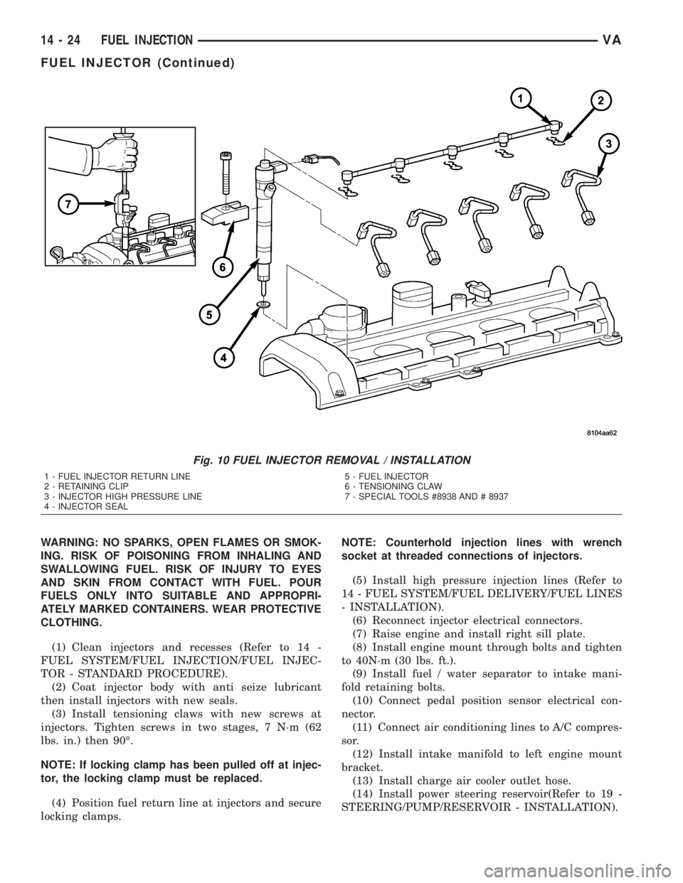
(32) Remove injectors (Fig. 10).
(33) Clean injectors and recesses (Refer to 14 -
FUEL SYSTEM/FUEL INJECTION/FUEL INJEC-
TOR - STANDARD PROCEDURE).
INSTALLATION
WARNING: HIGH-PRESSURE FUEL LINES DELIVER
DIESEL FUEL UNDER EXTREME PRESSURE FROM
THE INJECTION PUMP TO THE FUEL INJECTORS.
THIS MAY BE AS HIGH AS 1600BAR (23,200 PSI).
USE EXTREME CAUTION WHEN INSPECTING FOR
HIGH-PRESSURE FUEL LEAKS. FUEL UNDER THIS
AMOUNT OF PRESSURE CAN PENETRATE SKIN
CAUSING PERSONAL INJURY OR DEATH. INSPECT
FOR HIGH-PRESSURE LEAKS WITH A SHEET OF
CARD BOARD. WEAR SAFETY GOGGLES AND
ADEQUATE PROTECTIVE CLOTHING WHEN SER-
VICING FUEL SYSTEM.
VAFUEL INJECTION 14 - 23
FUEL INJECTOR (Continued)
Page 852 of 1232
WARNING: NO SPARKS, OPEN FLAMES OR SMOK-
ING. RISK OF POISONING FROM INHALING AND
SWALLOWING FUEL. RISK OF INJURY TO EYES
AND SKIN FROM CONTACT WITH FUEL. POUR
FUELS ONLY INTO SUITABLE AND APPROPRI-
ATELY MARKED CONTAINERS. WEAR PROTECTIVE
CLOTHING.
(1) Clean injectors and recesses (Refer to 14 -
FUEL SYSTEM/FUEL INJECTION/FUEL INJEC-
TOR - STANDARD PROCEDURE).
(2) Coat injector body with anti seize lubricant
then install injectors with new seals.
(3) Install tensioning claws with new screws at
injectors. Tighten screws in two stages, 7 N´m (62
lbs. in.) then 90É.
NOTE: If locking clamp has been pulled off at injec-
tor, the locking clamp must be replaced.
(4) Position fuel return line at injectors and secure
locking clamps.NOTE: Counterhold injection lines with wrench
socket at threaded connections of injectors.
(5) Install high pressure injection lines (Refer to
14 - FUEL SYSTEM/FUEL DELIVERY/FUEL LINES
- INSTALLATION).
(6) Reconnect injector electrical connectors.
(7) Raise engine and install right sill plate.
(8) Install engine mount through bolts and tighten
to 40N´m (30 lbs. ft.).
(9) Install fuel / water separator to intake mani-
fold retaining bolts.
(10) Connect pedal position sensor electrical con-
nector.
(11) Connect air conditioning lines to A/C compres-
sor.
(12) Install intake manifold to left engine mount
bracket.
(13) Install charge air cooler outlet hose.
(14) Install power steering reservoir(Refer to 19 -
STEERING/PUMP/RESERVOIR - INSTALLATION).
Fig. 10 FUEL INJECTOR REMOVAL / INSTALLATION
1 - FUEL INJECTOR RETURN LINE
2 - RETAINING CLIP
3 - INJECTOR HIGH PRESSURE LINE
4 - INJECTOR SEAL5 - FUEL INJECTOR
6 - TENSIONING CLAW
7 - SPECIAL TOOLS #8938 AND # 8937
14 - 24 FUEL INJECTIONVA
FUEL INJECTOR (Continued)
Page 853 of 1232
(15) Install battery tray(Refer to 8 - ELECTRI-
CAL/BATTERY SYSTEM/TRAY - INSTALLATION).
(16) Connect PDC to battery tray.
(17) Install battery (Refer to 8 - ELECTRICAL/
BATTERY SYSTEM/BATTERY - INSTALLATION).
(18) Connect steering coupler at gear box (RHD
Only).
(19) Install turbocharger to right engine mount
bracket (Refer to 11 - EXHAUST SYSTEM/TURBO-
CHARGER SYSTEM - INSTALLATION).
(20) Install charge air cooler to turbocharger inlet
adaptor (Refer to 11 - EXHAUST SYSTEM/CHARGE
AIR COOLER AND PLUMBING - INSTALLATION) .
(21) Install charger air cooler inlet hose (Refer to
11 - EXHAUST SYSTEM/CHARGE AIR COOLER
AND PLUMBING - INSTALLATION).
(22) Install air cleaner box assembly and hoses.
(23) Install upper radiator hose.
(24) Raise vehicle.
(25) Install dipstick tube into oil pan and tighten
retaining bolt.
(26) Install turbocharger down pipe assembly.
(27) Close cooling system drain.
(28) Install lower radiator deflector plate.
(29) Lower vehicle.
(30) Connect negative battery cable.
(31) Install engine cover (Refer to 9 - ENGINE -
INSTALLATION)..
(32) Fill cooling system with the correct mixture to
the proper level (Refer to 7 - COOLING/ENGINE/
COOLANT - STANDARD PROCEDURE).
WARNING: USE EXTREME CAUTION WHEN THE
ENGINE IS OPERATING. DO NOT PUT YOUR
HANDS NEAR PULLEYS, BELTS OR FAN. DO NOT
WEAR LOOSE CLOTHING.
(33) Start engine and inspect for leaks.
(34) Recharge air conditioning system.
FUEL PRESSURE SENSOR
DESCRIPTION
DESCRIPTION
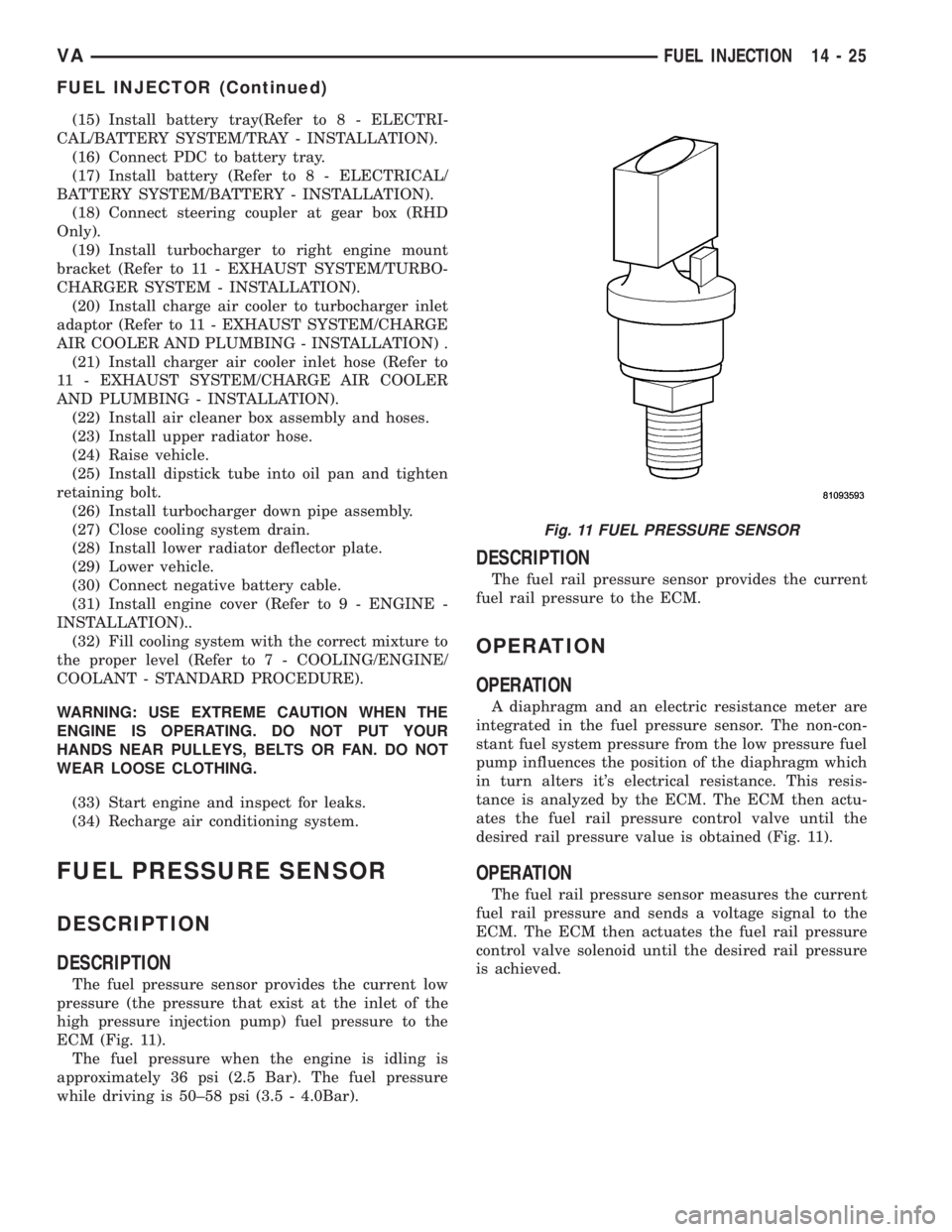
The fuel pressure sensor provides the current low
pressure (the pressure that exist at the inlet of the
high pressure injection pump) fuel pressure to the
ECM (Fig. 11).
The fuel pressure when the engine is idling is
approximately 36 psi (2.5 Bar). The fuel pressure
while driving is 50±58 psi (3.5 - 4.0Bar).
DESCRIPTION
The fuel rail pressure sensor provides the current
fuel rail pressure to the ECM.
OPERATION
OPERATION
A diaphragm and an electric resistance meter are
integrated in the fuel pressure sensor. The non-con-
stant fuel system pressure from the low pressure fuel
pump influences the position of the diaphragm which
in turn alters it's electrical resistance. This resis-
tance is analyzed by the ECM. The ECM then actu-
ates the fuel rail pressure control valve until the
desired rail pressure value is obtained (Fig. 11).
OPERATION
The fuel rail pressure sensor measures the current
fuel rail pressure and sends a voltage signal to the
ECM. The ECM then actuates the fuel rail pressure
control valve solenoid until the desired rail pressure
is achieved.
Fig. 11 FUEL PRESSURE SENSOR
VAFUEL INJECTION 14 - 25
FUEL INJECTOR (Continued)