2005 MERCEDES-BENZ SPRINTER wheel torque
[x] Cancel search: wheel torquePage 65 of 1232
BRAKES
TABLE OF CONTENTS
page page
BRAKES - BASE........................... 1BRAKES - ABS........................... 29
BRAKES - BASE
TABLE OF CONTENTS
page page
BRAKES - BASE
DIAGNOSIS AND TESTING - BASE BRAKE
SYSTEM.............................2
STANDARD PROCEDURE
STANDARD PROCEDURE - MANUAL
BLEEDING............................4
STANDARD PROCEDURE - PRESSURE
BLEEDING............................5
HYDRAULIC/MECHANICAL
SPECIFICATIONS
SPECIFICATIONS - TORQUE CHART.......5
BASE BRAKE.........................6
SPECIAL TOOLS
BRAKES.............................7
BRAKE LINES
STANDARD PROCEDURE
STANDARD PROCEDURE - ISO FLARING . . . 8
STANDARD PROCEDURE - DOUBLE
INVERTED FLARING....................8
BRAKE PADS/SHOES
REMOVAL
REMOVAL - FRONT (SRW)...............9
REMOVAL - FRONT (DRW)...............9
REMOVAL - REAR (16º WHEELS) (SRW)....9
REMOVAL - REAR (15º WHEELS) (SRW)....9
REMOVAL - REAR (DRW)...............10
INSTALLATION
INSTALLATION - FRONT (SRW)..........10
INSTALLATION - FRONT (DRW)..........11
INSTALLATION - REAR (16º WHEELS)
(SRW) ..............................11
INSTALLATION - REAR (16º WHEELS)
(SRW) ..............................11
INSTALLATION - REAR (DRW)...........11
DISC BRAKE CALIPERS
REMOVAL
REMOVAL - FRONT (SRW)..............11REMOVAL - FRONT (DRW)..............12
REMOVAL - REAR (SRW)...............12
REMOVAL - REAR (DRW)...............12
INSTALLATION
INSTALLATION - FRONT (SRW)..........12
INSTALLATION - FRONT (DRW)..........13
INSTALLATION - REAR (SRW)...........13
INSTALLATION - REAR (DRW)...........13
DISC BRAKE CALIPER ADAPTER
REMOVAL
REMOVAL - FRONT....................13
REMOVAL - REAR.....................13
INSTALLATION
INSTALLATION - FRONT................14
INSTALLATION - REAR.................14
FLUID
DIAGNOSIS AND TESTING - BRAKE FLUID
CONTAMINATION.....................14
STANDARD PROCEDURE - BRAKE FLUID
LEVEL..............................14
SPECIFICATIONS
BRAKE FLUID........................14
FLUID RESERVOIR
REMOVAL.............................15
INSTALLATION.........................15
ALB LEVER
REMOVAL.............................15
INSTALLATION.........................15
ALB CONTROLLER
REMOVAL.............................15
INSTALLATION.........................15
ADJUSTMENTS
ADJUSTMENT........................16
MASTER CYLINDER
DIAGNOSIS AND TESTING - MASTER
CYLINDER/POWER BOOSTER...........16
VABRAKES 5 - 1
Page 66 of 1232
STANDARD PROCEDURE - MASTER
CYLINDER BLEEDING..................17
REMOVAL.............................17
INSTALLATION.........................18
PEDAL
REMOVAL.............................18
INSTALLATION.........................19
POWER BRAKE BOOSTER
DESCRIPTION.........................19
OPERATION...........................19
REMOVAL.............................19
INSTALLATION.........................19
ROTORS
REMOVAL
REMOVAL - FRONT (SRW)..............19
REMOVAL - REAR (SRW)...............20
REMOVAL - FRONT (DRW)..............20
REMOVAL - REAR (DRW)...............20
INSTALLATION
INSTALLATION - FRONT (SRW)..........21
INSTALLATION - REAR (SRW)...........21
INSTALLATION - FRONT (DRW)..........21
INSTALLATION - REAR (DRW)...........21
SUPPORT PLATE
REMOVAL - REAR......................22
INSTALLATION - REAR...................22
PARKING BRAKE
SPECIFICATIONS
TORQUE CHART......................22SPECIAL TOOLS
PARK BRAKE........................23
CABLE TENSIONER
REMOVAL.............................23
INSTALLATION.........................23
CABLES
REMOVAL
REMOVAL - FRONT....................24
REMOVAL - REAR.....................24
INSTALLATION
INSTALLATION - FRONT................24
INSTALLATION - REAR.................25
ADJUSTMENTS
ADJUSTMENT - PARKING BRAKE CABLES . 25
LEVER
REMOVAL.............................26
INSTALLATION.........................26
SHOES
REMOVAL
REMOVAL - (SRW)....................26
REMOVAL - (DRW)....................26
CLEANING - REAR DRUM IN HAT BRAKE....27
INSTALLATION
INSTALLATION - (SRW).................27
INSTALLATION - (DRW).................27
ADJUSTMENTS
ADJUSTMENT........................27
BRAKES - BASE
DIAGNOSIS AND TESTING - BASE BRAKE
SYSTEM
Base brake components consist of the brake pads,
calipers, brake drum in hat rotor in the rear, rotors,
brake lines, master cylinder, booster, and parking
brake components.
Brake diagnosis involves determining if the prob-
lem is related to a mechanical, hydraulic, or vacuum
operated component.
The first diagnosis step is the preliminary check.
PRELIMINARY BRAKE CHECK
(1) Check condition of tires and wheels. Damaged
wheels and worn, damaged, or underinflated tires
can cause pull, shudder, vibration, and a condition
similar to grab.
(2) If complaint was based on noise when braking,
check suspension components. Jounce front and rear
of vehicle and listen for noise that might be caused
by loose, worn or damaged suspension or steering
components.(3) Inspect brake fluid level and condition. Note
that the brake reservoir fluid level will decrease in
proportion to normal lining wear.Also note that
brake fluid tends to darken over time. This is
normal and should not be mistaken for contam-
ination.
(a) If fluid level is abnormally low, look for evi-
dence of leaks at calipers, wheel cylinders, brake
lines, and master cylinder.
(b) If fluid appears contaminated, drain out a
sample to examine. System will have to be flushed
if fluid is separated into layers, or contains a sub-
stance other than brake fluid. The system seals
and cups will also have to be replaced after flush-
ing. Use clean brake fluid to flush the system.
(4) Check parking brake operation. Verify free
movement and full release of cables and pedal. Also
note if vehicle was being operated with parking
brake partially applied.
(5) Check brake pedal operation. Verify that pedal
does not bind and has adequate free play. If pedal
lacks free play, check pedal and power booster for
being loose or for bind condition. Do not road test
until condition is corrected.
(6) Check booster vacuum check valve and hose.
(7) If components checked appear OK, road test
the vehicle.
5 - 2 BRAKES - BASEVA
Page 69 of 1232
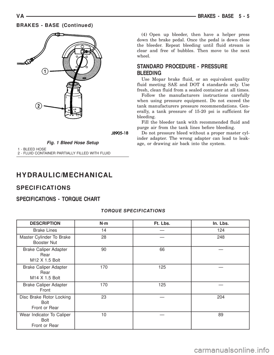
(4) Open up bleeder, then have a helper press
down the brake pedal. Once the pedal is down close
the bleeder. Repeat bleeding until fluid stream is
clear and free of bubbles. Then move to the next
wheel.
STANDARD PROCEDURE - PRESSURE
BLEEDING
Use Mopar brake fluid, or an equivalent quality
fluid meeting SAE and DOT 4 standards only. Use
fresh, clean fluid from a sealed container at all times.
Follow the manufacturers instructions carefully
when using pressure equipment. Do not exceed the
tank manufacturers pressure recommendations. Gen-
erally, a tank pressure of 15-20 psi is sufficient for
bleeding.
Fill the bleeder tank with recommended fluid and
purge air from the tank lines before bleeding.
Do not pressure bleed without a proper master cyl-
inder adapter. The wrong adapter can lead to leak-
age, or drawing air back into the system.
HYDRAULIC/MECHANICAL
SPECIFICATIONS
SPECIFICATIONS - TORQUE CHART
TORQUE SPECIFICATIONS
DESCRIPTION N´m Ft. Lbs. In. Lbs.
Brake Lines 14 Ð 124
Master Cylinder To Brake
Booster Nut28 Ð 248
Brake Caliper Adapter
Rear
M12 X 1.5 Bolt90 66 Ð
Brake Caliper Adapter
Rear
M14 X 1.5 Bolt170 125 Ð
Brake Caliper Adapter
Front170 125 Ð
Disc Brake Rotor Locking
Bolt
Front or Rear23 Ð 204
Wear Indicator To Caliper
Bolt
Front or Rear10 Ð 89
Fig. 1 Bleed Hose Setup
1 - BLEED HOSE
2 - FLUID CONTAINER PARTIALLY FILLED WITH FLUID
VABRAKES - BASE 5 - 5
BRAKES - BASE (Continued)
Page 86 of 1232
(3) Install the locking bolt for the rotor (Fig. 27).
Tighten to 23 N´m (204 in. lbs.).
(4) Install the disc brake caliper adapter (Fig. 27).
Tighten to 170 N´m (125 ft. lbs.) (Refer to 5 -
BRAKES/HYDRAULIC/MECHANICAL/DISC
BRAKE CALIPER ADAPTER - INSTALLATION).
(5) Install the wheel flange ring (Fig. 27) Tighten
to 200 N´m (148 ft. lbs.).
(6) Install the brake pads (Refer to 5 - BRAKES/
HYDRAULIC/MECHANICAL/BRAKE PADS/SHOES
- INSTALLATION) (Fig. 27).
(7) Release the parking brake.
(8) Adjust the parking brake (Refer to 5 -
BRAKES/PARKING BRAKE/SHOES - ADJUST-
MENTS).
(9) Press and release the brake pedal several times
until pressure has built up.
(10) Check fluid in reservoir and correct if neces-
sary.
(11) Install the rear wheels.
(12) Lower the vehicle.
SUPPORT PLATE
REMOVAL - REAR
(1) Raise and support the vehicle.
(2) Remove the disc brake caliper adapter (Refer to
5 - BRAKES/HYDRAULIC/MECHANICAL/DISC
BRAKE CALIPER ADAPTER - REMOVAL).
(3) Remove the disc brake rotor (Refer to 5 -
BRAKES/HYDRAULIC/MECHANICAL/ROTORS -
REMOVAL).(4) Remove the rear park brake shoes (Refer to 5 -
BRAKES/PARKING BRAKE/SHOES - REMOVAL).
(5) Remove the park brake cable from he support
plate.
(6) Remove the rear axle bearing (Refer to 3 - DIF-
FERENTIAL & DRIVELINE/REAR AXLE/AXLE
BEARINGS - REMOVAL).
(7) Remove brake support plate.
INSTALLATION - REAR
(1) Press the brake support plate with the axle
bearing onto the axle shaft (Refer to 3 - DIFFEREN-
TIAL & DRIVELINE/REAR AXLE/AXLE BEARINGS
- INSTALLATION).
(2) Install the park brake cable to the support
plate.
(3) Install the rear park brake shoes (Refer to 5 -
BRAKES/PARKING BRAKE/SHOES - INSTALLA-
TION).
(4) Install the disc brake rotor (Refer to 5 -
BRAKES/HYDRAULIC/MECHANICAL/ROTORS -
INSTALLATION).
(5) Install the disc brake caliper adapter (Refer to
5 - BRAKES/HYDRAULIC/MECHANICAL/DISC
BRAKE CALIPER ADAPTER - INSTALLATION).
(6) Adjust the rear park brake shoes (Refer to 5 -
BRAKES/PARKING BRAKE/SHOES - ADJUST-
MENTS).
(7) Install the rear wheels (Refer to 22 - TIRES/
WHEELS/WHEELS - INSTALLATION).
PARKING BRAKE
SPECIFICATIONS
TORQUE CHART
TORQUE SPECIFICATIONS
DESCRIPTION N´m Ft. Lbs. In. Lbs.
Pressure Transformer Unit
For Brake Cables To
Frame Crossmember25 Ð 221
Hand Brake Lever To Seat
Frame25 Ð 221
5 - 22 BRAKES - BASEVA
ROTORS (Continued)
Page 93 of 1232
BRAKES - ABS
TABLE OF CONTENTS
page page
BRAKES - ABS
SPECIFICATIONS - TORQUE CHART........29
ELECTRICAL
DESCRIPTION.........................29
OPERATION...........................29
FRONT WHEEL SPEED SENSOR
REMOVAL.............................30
INSTALLATION.........................30
REAR WHEEL SPEED SENSOR
REMOVAL.............................30INSTALLATION.........................31
TONE WHEEL
REMOVAL.............................31
INSTALLATION.........................31
HCU (HYDRAULIC CONTROL UNIT)
DESCRIPTION.........................31
REMOVAL.............................31
INSTALLATION.........................32
BRAKES - ABS
SPECIFICATIONS - TORQUE CHART
TORQUE SPECIFICATIONS
DESCRIPTION N´m Ft. Lbs. In. Lbs.
Brake Lines To Hydraulic
unit16 Ð 12
ELECTRICAL
DESCRIPTION
NOTE: Wheel speed sensor should be installed all
the way into the clamping bushings, the wheel
speed sensor will self adjust when the vehicle is
moved.
The ABS brake system uses 4 wheel speed sensors.
A sensor is mounted to each front hub/bearings in
the front. A rear sensor is mounted to each rear sup-
port plate.
OPERATION
The Wheel Speed Sensor consists of a magnet sur-
rounded by windings from a single strand of wire.
The sensor sends a small AC signal to the CAB. This
signal is generated by magnetic induction. The mag-
netic induction is created when a toothed sensor ring
(exciter ring or tone wheel) passes the stationary
magnetic WSS.When the ring gear is rotated, the exciter ring
passes the tip of the WSS. As the exciter ring tooth
approaches the tip of the WSS, the magnetic lines of
force expand, causing the magnetic field to cut across
the sensor's windings. This, in turn causes current to
flow through the WSS circuit (Fig. 1) in one direc-
tion. When the exciter ring tooth moves away from
the sensor tip, the magnetic lines of force collapse
cutting the winding in the opposite direction. This
causes the current to flow in the opposite direction.
Every time a tooth of the exciter ring passes the tip
of the WSS, an AC signal is generated. Each AC sig-
nal (positive to negative signal or sinewave) is inter-
preted by the CAB. It then compares the frequency of
the sinewave to a time value to calculate vehicle
speed. The CAB continues to monitor the frequency
to determine a deceleration rate that would indicate
a possible wheel-locking tendency.
The signal strength of any magnetic induction sen-
sor is directly affected by:
²Magnetic field strength; the stronger the mag-
netic field, the stronger the signal
VABRAKES - ABS 5 - 29
Page 125 of 1232
TRANSMISSION CONTROL
MODULE
DESCRIPTION
The transmission control module (TCM) receives,
processes and sends various digital and analog sig-
nals related to the automatic transmission. In addi-
tion, it processes information received from other
vehicle systems, such as engine torque and speed,
accelerator pedal position, wheel speed, kick-down
switch, traction control information, etc.
The TCM is located under the driver's seat and is
connected to other control modules via a CAN bus. It
controls all shift functions to achieve smooth shift
comfort in all driving situations considering:
²Vehicle speed.
²Transmission status.
²Position of selector lever.
²Selected shift range.
²CAN signals.
²Engine Status.Engine speed limits may be reached in all gears
with full throttle or in kick-down operation. In for-
ward driving, the shift range of the forward gears
can be adjusted by the operator by tipping the selec-
tor lever to the left or right (AutoStick). However, the
TCM features a downshift inhibitor to prevent the
engine from overspeeding.
OPERATION
The transmission control module (TCM) deter-
mines the current operating conditions of the vehicle
and controls the shifting process for shift comfort and
driving situations. It receives this operating data
from sensors and broadcast messages from other
modules.
The TCM uses inputs from several sensors that are
directly hardwired to the controller and it uses sev-
eral indirect inputs that are used to control shifts.
This information is used to actuate the proper sole-
noids in the valve body to achieve the desired gear.
The shift lever assembly (SLA) has several items
that are monitored by the TCM to calculate shift
lever position. The reverse light switch, an integral
part of the SLA, controls the reverse light relay con-
trol circuit. The Brake/Transmission Shift Interlock
(BTSI) solenoid and the park lockout solenoid (also
part of the SLA) are controlled by the TCM.
The ECM and ABS broadcast messages over the
controller area network (CAN C) bus for use by the
TCM. The TCM uses this information, with other
inputs, to determine the transmission operating con-
ditions.
The TCM:
²determines the momentary operating conditions
of the vehicle.
²controls all shift processes.
²considers shift comfort and the driving situation.
The TCM controls the solenoid valves for modulat-
ing shift pressures and gear changes. Relative to the
torque being transmitted, the required pressures are
calculated from load conditions, engine rpm, vehicle
speed, and ATF temperature.
The following functions are contained in the TCM:
²Shift Program
²Downshift Safety
²Torque Converter Lock-Up Clutch.
²Adaptation.
This transmission does not have a TCM relay.
Power is supplied to the SLA and the TCM directly
from the ignition.
Fig. 3 ECM
1 - BRACKET
2 - ECM
3 - BRACKET TENSIONING SPRINGS
VAELECTRONIC CONTROL MODULES 8E - 5
ENGINE CONTROL MODULE (Continued)
Page 126 of 1232
The TCM continuously checks for electrical prob-
lems, mechanical problems, and some hydraulic prob-
lems. When a problem is sensed, the TCM stores a
diagnostic trouble code (DTC). Some of these codes
cause the transmission to go into9Limp-In9or
9default9mode. Some DTCs cause permanent
Limp-In and others cause temporary Limp-In. The
NAG1 defaults in the current gear position if a DTC
is detected, then after a key cycle the transmission
will go into Limp-in, which is mechanical 2nd gear.
Some DTCs may allow the transmission to resume
normal operation (recover) if the detected problem
goes away. A permanent Limp-In DTC will recover
when the key is cycled, but if the same DTC is
detected for three key cycles the system will not
recover and the DTC must be cleared from the TCM
with the DRBIIItscan tool.
TCM SIGNALS
The TCM registers one part of the input signals by
direct inputs, the other part by CAN C bus. In addi-
tion to the direct control of the actuators, the TCM
sends various output signals by CAN C bus to other
control modules.
Selector Lever Position
The TCM monitors the SLA for all shift lever posi-
tions via the CAN bus.
ATF Temperature Sensor
The ATF temperature sensor is a positive temper-
ature co-efficient (PTC) thermistor. It measures the
temperature of the transmission fluid and is a direct
input signal for the TCM. The temperature of the
ATF has an influence on the shifttime and resulting
shift quality. As the temperature rises, resistance
rises, and therefore, the probing voltage is decreas-
ing. Because of its registration, the shifting process
can be optimized in all temperature ranges.
The ATF temperature sensor is wired in series
with the park/neutral contact. The temperature sig-
nal is transmitted to the TCM only when the reed
contact of the park/neutral contact is closed because
the TCM only reads ATF temperature while in any
forward gear, or REVERSE. When the transmission
is in PARK or NEUTRAL, the TCM will substitute
the engine temperature for the ATF temperature.
Starter Interlock
The TCM monitors a contact switch wired in series
with the transmission temperature sensor to deter-
mine PARK and NEUTRAL positions. The contact
switch is open in PARK and NEUTRAL. The TCM
senses transmission temperature as high (switch
supply voltage), confirming switch status as open.
The TCM then broadcasts a message over CAN bus
to confirm switch status. The PCM receives thisinformation and allows operation of the starter cir-
cuit.
N2 and N3 Speed Sensors
The N2 and N3 Input Speed Sensors are two Hall-
effect speed sensors that are mounted internally in
the transmission and are used by the TCM to calcu-
late the transmission's input speed. Since the input
speed cannot be measured directly, two of the drive
elements are measured. Two input speed sensors
were required because both drive elements are not
active in all gears.
CAN C Bus Indirect Input Signals
A 2.5-volt bias (operating voltage) is present on the
CAN C bus any time the ignition switch is in the
RUN position. Both the TCM and the ABS apply this
bias. On this vehicle, the CAN C bus is used for mod-
ule data exchange only. The indirect inputs used on
the NAG1 electronic control system are:
²Wheel Speed Sensors.
²Brake Switch.
²Engine RPM.
²Engine Temperature.
²Cruise Control Status.
²Gear Limit Request.
²Throttle Position - 0% at idle, 100% at WOT. If
open, TCM assumes idle (0% throttle opening).
²Odometer Mileage
²Maximum Effective Torque.
²Engine in Limp-In Mode/Mileage Where DTC
Was Set.
BRAKE TRANSMISSION SHIFT INTERLOCK (BTSI)
The BTSI solenoid prevents shifting out of the
PARK position until the ignition key is in the RUN
position and the brake pedal is pressed. The TCM
controls the ground while the ignition switch supplies
power to the BTSI solenoid. The PCM monitors the
brake switch and broadcasts brake switch status
messages over the CAN C bus. If the park brake is
depressed and there is power (Run/Start) to SLA, the
BTSI solenoid deactivates.
SHIFT SCHEDULES
The basic shift schedule includes up and down-
shifts for all five gears. The TCM adapts the shift
program according to driving style, accelerator pedal
position and deviation of vehicle speed. Influencing
factors are:
²Road Conditions.
²Incline, Decline and Altitude.
²Trailer Operation, Loading.
²Engine Coolant Temperature.
²Cruise Control Operation.
²Sporty Driving Style.
8E - 6 ELECTRONIC CONTROL MODULESVA
TRANSMISSION CONTROL MODULE (Continued)
Page 152 of 1232
STARTING SYSTEM
TABLE OF CONTENTS
page page
STARTING SYSTEM
DESCRIPTION.........................24
OPERATION...........................24
DIAGNOSIS AND TESTING - STARTING
SYSTEM............................25
SPECIFICATIONS
TORQUE - STARTER - DIESEL...........29
SPECIFICATIONS - STARTER MOTOR -
DIESEL.............................29STARTER MOTOR
DIAGNOSIS AND TESTING - STARTER
MOTOR .............................29
REMOVAL.............................30
INSTALLATION.........................31
STARTER MOTOR RELAY
DESCRIPTION.........................31
REMOVAL.............................31
INSTALLATION.........................32
STARTING SYSTEM
DESCRIPTION
The starting system consists of:
²Starter relay
²Starter motor (including an integral starter sole-
noid)
Other components to be considered as part of start-
ing system are:
²Battery
²Battery cables
²Ignition switch and key lock cylinder
²Park/neutral position switch (automatic trans-
mission)
²Wire harnesses and connections.
The Battery, Starting, and Charging systems oper-
ate in conjunction with one another, and must be
tested as a complete system. For correct operation of
starting/charging systems, all components used in
these 3 systems must perform within specifications.
When attempting to diagnose any of these systems, it
is important that you keep their interdependency in
mind.
The diagnostic procedures used in each of these
groups include the most basic conventional diagnostic
methods, to the more sophisticated On-Board Diag-
nostics (OBD) built into the Engine Control Module
(ECM). Use of an induction-type milliampere amme-
ter, volt/ohmmeter, battery charger, carbon pile rheo-
stat (load tester), and 12-volt test lamp may be
required.
Certain starting system components are monitored
by the ECM and may produce a Diagnostic Trouble
Code (DTC).
OPERATION
The starting system components form two separate
circuits. A high-amperage feed circuit that feeds thestarter motor high-amperage, and a low-amperage
control circuit that operates on less than 20 amperes.
The high-amperage feed circuit components include
the battery, the battery cables, the contact disc por-
tion of the starter solenoid, and the starter motor
itself. The low-amperage control circuit components
include the ignition switch, the park/neutral position
switch (automatic transmission), the starter relay,
the electromagnetic windings of the starter solenoid,
and the connecting wire harness components.
If the vehicle is equipped with an automatic trans-
mission, battery voltage is supplied through the low-
amperage control circuit to the coil battery terminal
of the starter relay when the ignition switch is
turned to the momentary Start position. The park/
neutral position switch is installed in series between
the starter relay coil ground terminal and ground.
This normally open switch prevents the starter relay
from being energized and the starter motor from
operating unless the automatic transmission gear
selector is in the Neutral or Park positions.
When the starter relay coil is energized, the nor-
mally open relay contacts close. The relay contacts
connect the relay common feed terminal to the relay
normally open terminal. The closed relay contacts
energize the starter solenoid coil windings.
The energized solenoid pull-in coil pulls in the sole-
noid plunger. The solenoid plunger pulls the shift
lever in the starter motor. This engages the starter
overrunning clutch and pinion gear with the starter
ring gear on the manual transmission flywheel or on
the automatic transmission torque converter or
torque converter drive plate.
As the solenoid plunger reaches the end of its
travel, the solenoid contact disc completes the high-
amperage starter feed circuit and energizes the sole-
noid plunger hold-in coil. Current now flows between
the solenoid battery terminal and the starter motor,
energizing the starter.
8F - 24 STARTING SYSTEMVA