2005 MERCEDES-BENZ SPRINTER wheel torque
[x] Cancel search: wheel torquePage 891 of 1232
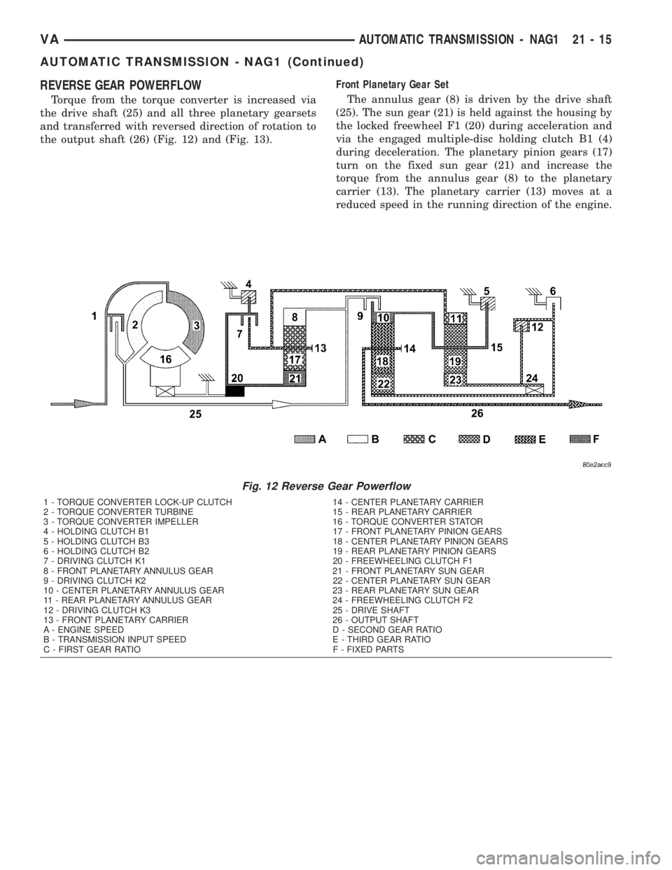
REVERSE GEAR POWERFLOW
Torque from the torque converter is increased via
the drive shaft (25) and all three planetary gearsets
and transferred with reversed direction of rotation to
the output shaft (26) (Fig. 12) and (Fig. 13).Front Planetary Gear Set
The annulus gear (8) is driven by the drive shaft
(25). The sun gear (21) is held against the housing by
the locked freewheel F1 (20) during acceleration and
via the engaged multiple-disc holding clutch B1 (4)
during deceleration. The planetary pinion gears (17)
turn on the fixed sun gear (21) and increase the
torque from the annulus gear (8) to the planetary
carrier (13). The planetary carrier (13) moves at a
reduced speed in the running direction of the engine.
Fig. 12 Reverse Gear Powerflow
1 - TORQUE CONVERTER LOCK-UP CLUTCH 14 - CENTER PLANETARY CARRIER
2 - TORQUE CONVERTER TURBINE 15 - REAR PLANETARY CARRIER
3 - TORQUE CONVERTER IMPELLER 16 - TORQUE CONVERTER STATOR
4 - HOLDING CLUTCH B1 17 - FRONT PLANETARY PINION GEARS
5 - HOLDING CLUTCH B3 18 - CENTER PLANETARY PINION GEARS
6 - HOLDING CLUTCH B2 19 - REAR PLANETARY PINION GEARS
7 - DRIVING CLUTCH K1 20 - FREEWHEELING CLUTCH F1
8 - FRONT PLANETARY ANNULUS GEAR 21 - FRONT PLANETARY SUN GEAR
9 - DRIVING CLUTCH K2 22 - CENTER PLANETARY SUN GEAR
10 - CENTER PLANETARY ANNULUS GEAR 23 - REAR PLANETARY SUN GEAR
11 - REAR PLANETARY ANNULUS GEAR 24 - FREEWHEELING CLUTCH F2
12 - DRIVING CLUTCH K3 25 - DRIVE SHAFT
13 - FRONT PLANETARY CARRIER 26 - OUTPUT SHAFT
A - ENGINE SPEED D - SECOND GEAR RATIO
B - TRANSMISSION INPUT SPEED E - THIRD GEAR RATIO
C - FIRST GEAR RATIO F - FIXED PARTS
VAAUTOMATIC TRANSMISSION - NAG1 21 - 15
AUTOMATIC TRANSMISSION - NAG1 (Continued)
Page 892 of 1232
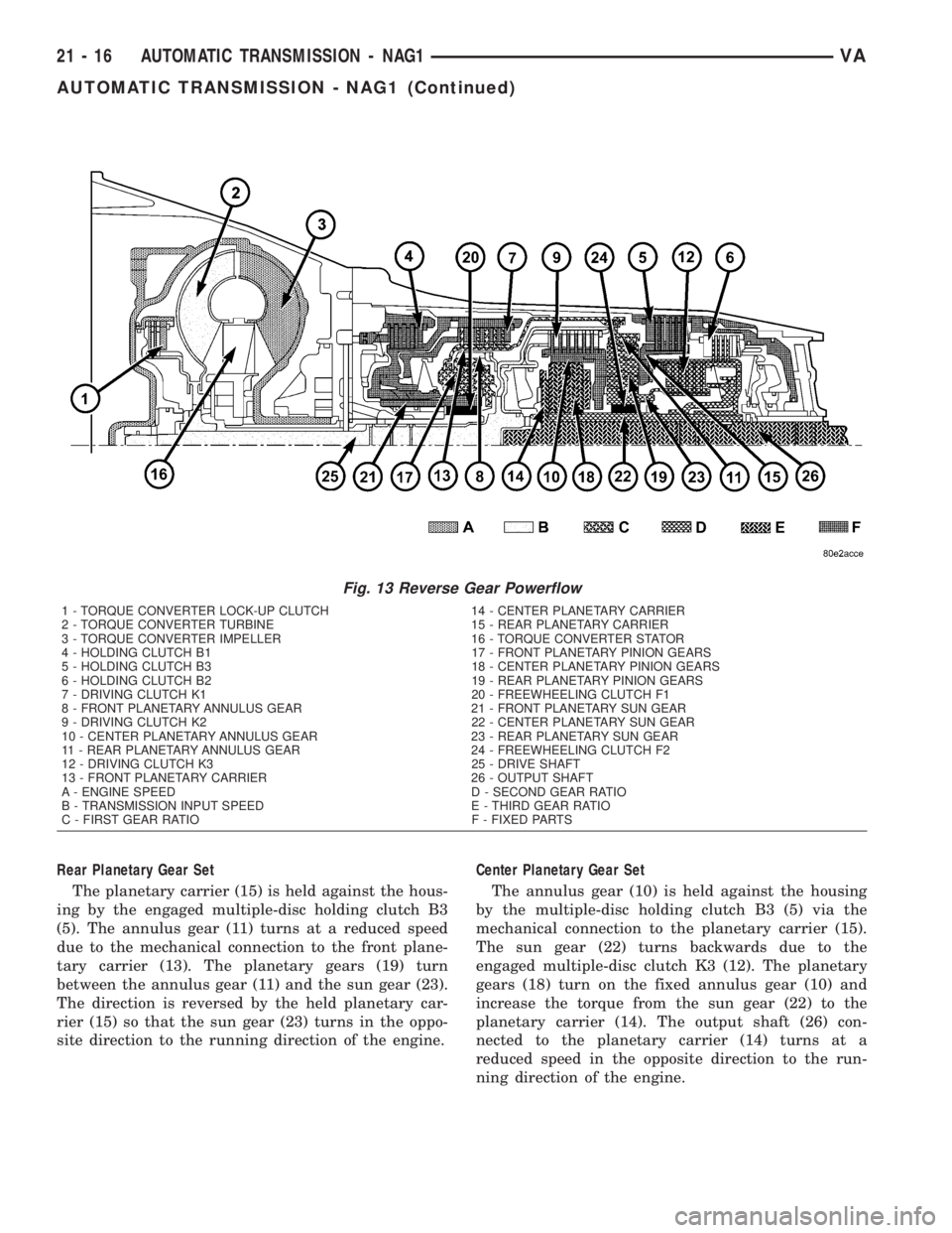
Rear Planetary Gear Set
The planetary carrier (15) is held against the hous-
ing by the engaged multiple-disc holding clutch B3
(5). The annulus gear (11) turns at a reduced speed
due to the mechanical connection to the front plane-
tary carrier (13). The planetary gears (19) turn
between the annulus gear (11) and the sun gear (23).
The direction is reversed by the held planetary car-
rier (15) so that the sun gear (23) turns in the oppo-
site direction to the running direction of the engine.Center Planetary Gear Set
The annulus gear (10) is held against the housing
by the multiple-disc holding clutch B3 (5) via the
mechanical connection to the planetary carrier (15).
The sun gear (22) turns backwards due to the
engaged multiple-disc clutch K3 (12). The planetary
gears (18) turn on the fixed annulus gear (10) and
increase the torque from the sun gear (22) to the
planetary carrier (14). The output shaft (26) con-
nected to the planetary carrier (14) turns at a
reduced speed in the opposite direction to the run-
ning direction of the engine.
Fig. 13 Reverse Gear Powerflow
1 - TORQUE CONVERTER LOCK-UP CLUTCH 14 - CENTER PLANETARY CARRIER
2 - TORQUE CONVERTER TURBINE 15 - REAR PLANETARY CARRIER
3 - TORQUE CONVERTER IMPELLER 16 - TORQUE CONVERTER STATOR
4 - HOLDING CLUTCH B1 17 - FRONT PLANETARY PINION GEARS
5 - HOLDING CLUTCH B3 18 - CENTER PLANETARY PINION GEARS
6 - HOLDING CLUTCH B2 19 - REAR PLANETARY PINION GEARS
7 - DRIVING CLUTCH K1 20 - FREEWHEELING CLUTCH F1
8 - FRONT PLANETARY ANNULUS GEAR 21 - FRONT PLANETARY SUN GEAR
9 - DRIVING CLUTCH K2 22 - CENTER PLANETARY SUN GEAR
10 - CENTER PLANETARY ANNULUS GEAR 23 - REAR PLANETARY SUN GEAR
11 - REAR PLANETARY ANNULUS GEAR 24 - FREEWHEELING CLUTCH F2
12 - DRIVING CLUTCH K3 25 - DRIVE SHAFT
13 - FRONT PLANETARY CARRIER 26 - OUTPUT SHAFT
A - ENGINE SPEED D - SECOND GEAR RATIO
B - TRANSMISSION INPUT SPEED E - THIRD GEAR RATIO
C - FIRST GEAR RATIO F - FIXED PARTS
21 - 16 AUTOMATIC TRANSMISSION - NAG1VA
AUTOMATIC TRANSMISSION - NAG1 (Continued)
Page 900 of 1232
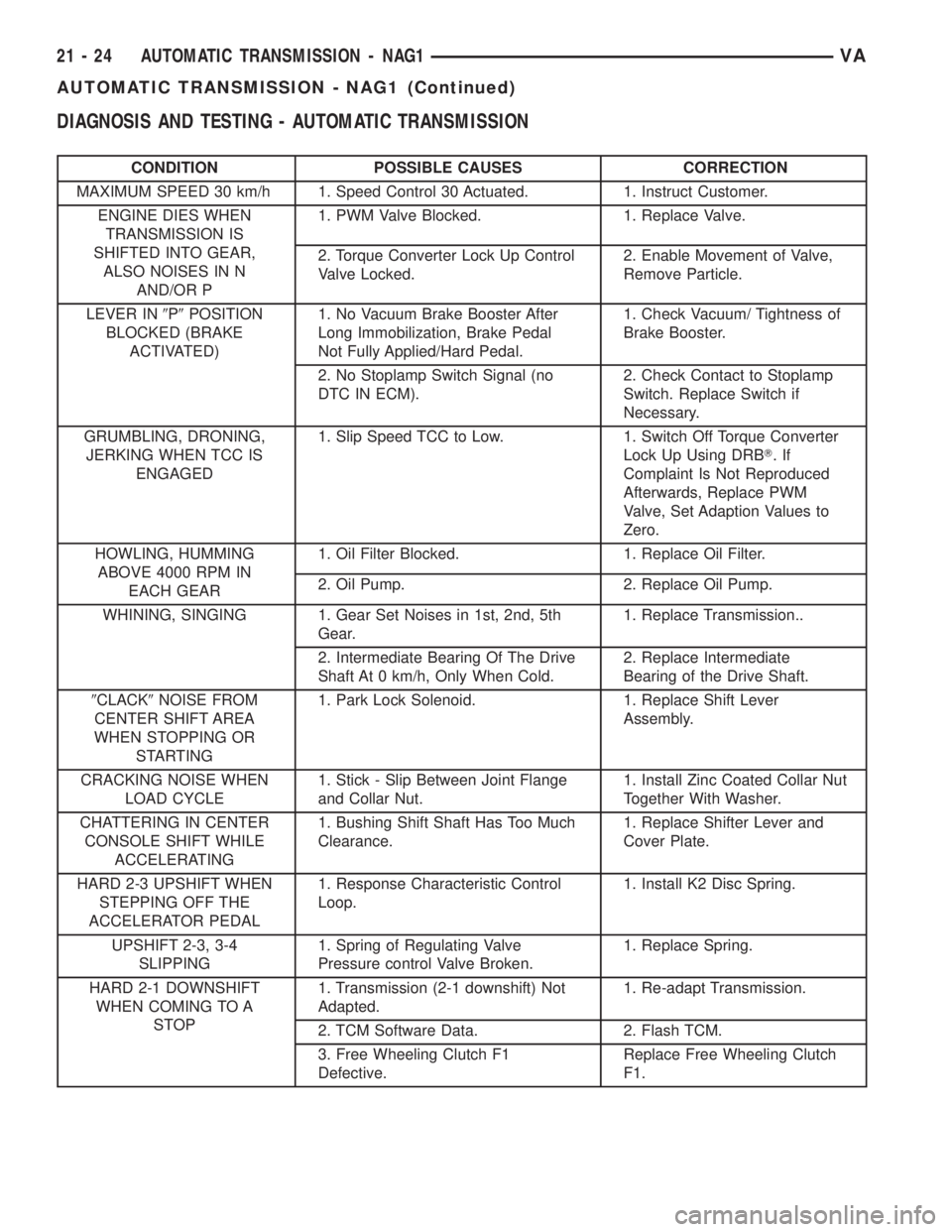
DIAGNOSIS AND TESTING - AUTOMATIC TRANSMISSION
CONDITION POSSIBLE CAUSES CORRECTION
MAXIMUM SPEED 30 km/h 1. Speed Control 30 Actuated. 1. Instruct Customer.
ENGINE DIES WHEN
TRANSMISSION IS
SHIFTED INTO GEAR,
ALSO NOISES IN N
AND/OR P1. PWM Valve Blocked. 1. Replace Valve.
2. Torque Converter Lock Up Control
Valve Locked.2. Enable Movement of Valve,
Remove Particle.
LEVER IN9P9POSITION
BLOCKED (BRAKE
ACTIVATED)1. No Vacuum Brake Booster After
Long Immobilization, Brake Pedal
Not Fully Applied/Hard Pedal.1. Check Vacuum/ Tightness of
Brake Booster.
2. No Stoplamp Switch Signal (no
DTC IN ECM).2. Check Contact to Stoplamp
Switch. Replace Switch if
Necessary.
GRUMBLING, DRONING,
JERKING WHEN TCC IS
ENGAGED1. Slip Speed TCC to Low. 1. Switch Off Torque Converter
Lock Up Using DRBT.If
Complaint Is Not Reproduced
Afterwards, Replace PWM
Valve, Set Adaption Values to
Zero.
HOWLING, HUMMING
ABOVE 4000 RPM IN
EACH GEAR1. Oil Filter Blocked. 1. Replace Oil Filter.
2. Oil Pump. 2. Replace Oil Pump.
WHINING, SINGING 1. Gear Set Noises in 1st, 2nd, 5th
Gear.1. Replace Transmission..
2. Intermediate Bearing Of The Drive
Shaft At 0 km/h, Only When Cold.2. Replace Intermediate
Bearing of the Drive Shaft.
9CLACK9NOISE FROM
CENTER SHIFT AREA
WHEN STOPPING OR
STARTING1. Park Lock Solenoid. 1. Replace Shift Lever
Assembly.
CRACKING NOISE WHEN
LOAD CYCLE1. Stick - Slip Between Joint Flange
and Collar Nut.1. Install Zinc Coated Collar Nut
Together With Washer.
CHATTERING IN CENTER
CONSOLE SHIFT WHILE
ACCELERATING1. Bushing Shift Shaft Has Too Much
Clearance.1. Replace Shifter Lever and
Cover Plate.
HARD 2-3 UPSHIFT WHEN
STEPPING OFF THE
ACCELERATOR PEDAL1. Response Characteristic Control
Loop.1. Install K2 Disc Spring.
UPSHIFT 2-3, 3-4
SLIPPING1. Spring of Regulating Valve
Pressure control Valve Broken.1. Replace Spring.
HARD 2-1 DOWNSHIFT
WHEN COMING TO A
STOP1. Transmission (2-1 downshift) Not
Adapted.1. Re-adapt Transmission.
2. TCM Software Data. 2. Flash TCM.
3. Free Wheeling Clutch F1
Defective.Replace Free Wheeling Clutch
F1.
21 - 24 AUTOMATIC TRANSMISSION - NAG1VA
AUTOMATIC TRANSMISSION - NAG1 (Continued)
Page 981 of 1232
(14) Remove the transmission oil filter and o-ring
from the electrohydraulic control unit.
(15) Clean the inside of the oil pan of any debris.
Inspect the oil pan gasket and replace if necessary.
(16) Install a new oil filter and o-ring into the elec-
trohydraulic control unit.
(17) Install the oil pan and gasket onto the trans-
mission.
(18) Install the oil pan bolts and retainers. Torque
the bolts to 8 N´m (70 in.lbs.).
(19) Lower the vehicle and add 7.0 L (7.4 qts.) of
transmission fluid to the transmission.
(20) Check the oil level (Refer to 21 - TRANSMIS-
SION/AUTOMATIC - NAG1/FLUID AND FILTER -
STANDARD PROCEDURE).
FREEWHEELING CLUTCH
DESCRIPTION
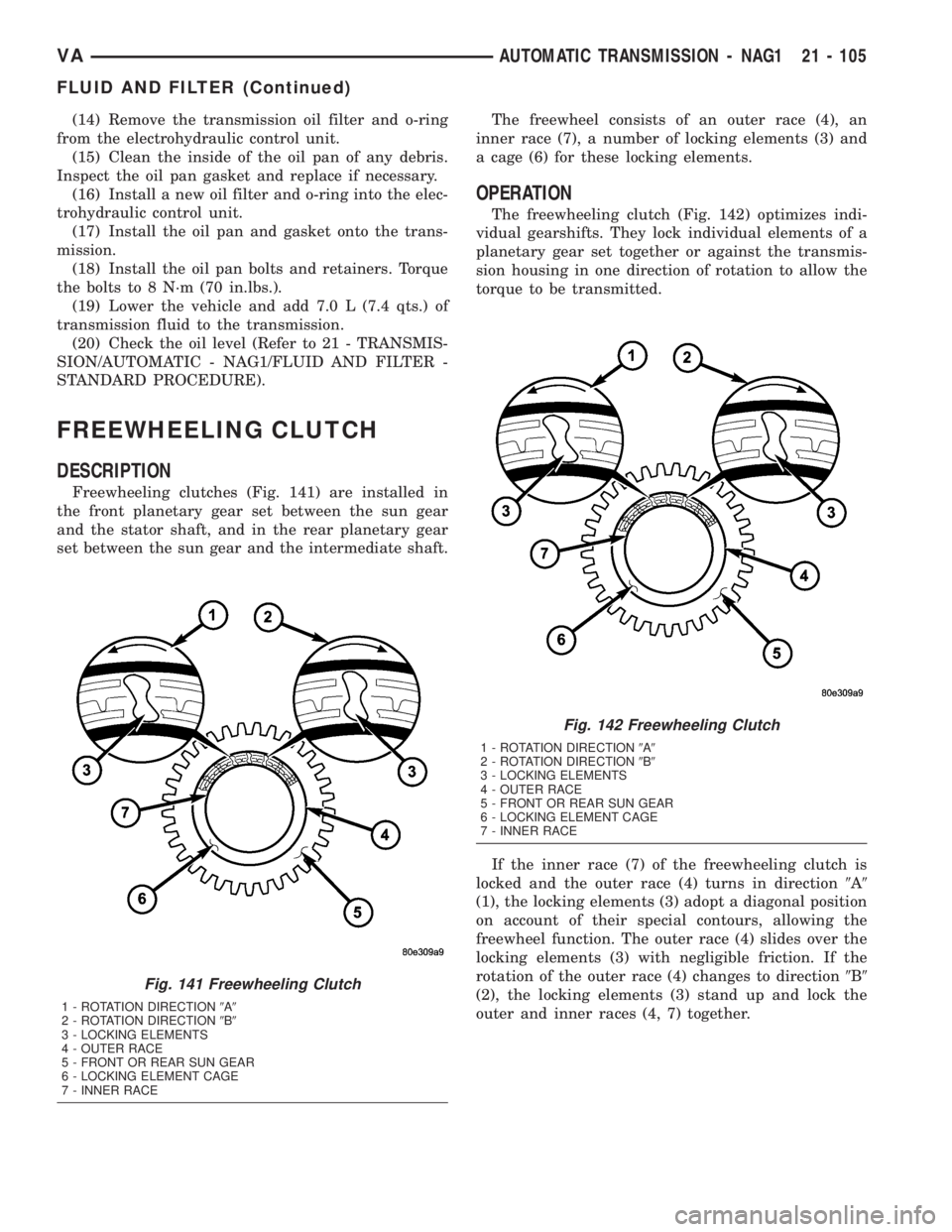
Freewheeling clutches (Fig. 141) are installed in
the front planetary gear set between the sun gear
and the stator shaft, and in the rear planetary gear
set between the sun gear and the intermediate shaft.The freewheel consists of an outer race (4), an
inner race (7), a number of locking elements (3) and
a cage (6) for these locking elements.
OPERATION
The freewheeling clutch (Fig. 142) optimizes indi-
vidual gearshifts. They lock individual elements of a
planetary gear set together or against the transmis-
sion housing in one direction of rotation to allow the
torque to be transmitted.
If the inner race (7) of the freewheeling clutch is
locked and the outer race (4) turns in direction9A9
(1), the locking elements (3) adopt a diagonal position
on account of their special contours, allowing the
freewheel function. The outer race (4) slides over the
locking elements (3) with negligible friction. If the
rotation of the outer race (4) changes to direction9B9
(2), the locking elements (3) stand up and lock the
outer and inner races (4, 7) together.
Fig. 141 Freewheeling Clutch
1 - ROTATION DIRECTION9A9
2 - ROTATION DIRECTION9B9
3 - LOCKING ELEMENTS
4 - OUTER RACE
5 - FRONT OR REAR SUN GEAR
6 - LOCKING ELEMENT CAGE
7 - INNER RACE
Fig. 142 Freewheeling Clutch
1 - ROTATION DIRECTION9A9
2 - ROTATION DIRECTION9B9
3 - LOCKING ELEMENTS
4 - OUTER RACE
5 - FRONT OR REAR SUN GEAR
6 - LOCKING ELEMENT CAGE
7 - INNER RACE
VAAUTOMATIC TRANSMISSION - NAG1 21 - 105
FLUID AND FILTER (Continued)
Page 996 of 1232
OIL PUMP
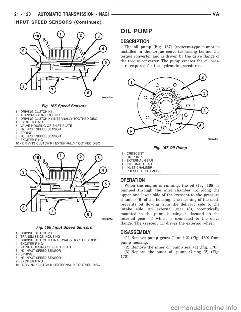
DESCRIPTION
The oil pump (Fig. 167) (crescent-type pump) is
installed in the torque converter casing behind the
torque converter and is driven by the drive flange of
the torque converter. The pump creates the oil pres-
sure required for the hydraulic procedures.
OPERATION
When the engine is running, the oil (Fig. 168) is
pumped through the inlet chamber (5) along the
upper and lower side of the crescent to the pressure
chamber (6) of the housing. The meshing of the teeth
prevents oil flowing from the delivery side to the
intake side. An external gear (3), eccentrically
mounted in the pump housing, is located on the
internal gear (4) which is connected to the drive
flange. The crescent (1) drives the external wheel.
DISASSEMBLY
(1) Remove pump gears (1 and 2) (Fig. 169) from
pump housing.
(2) Remove the inner oil pump seal (1) (Fig. 170).
(3) Replace the outer oil pump O-ring (2) (Fig.
170).
Fig. 165 Speed Sensors
1 - DRIVING CLUTCH K1
2 - TRANSMISSION HOUSING
3 - DRIVING CLUTCH K1 INTERNALLY TOOTHED DISC
4 - EXCITER RING
5 - VALVE HOUSING OF SHIFT PLATE
6 - N2 INPUT SPEED SENSOR
7 - SPRING
8 - N3 INPUT SPEED SENSOR
9 - EXCITER RING
10 - DRIVING CLUTCH K1 EXTERNALLY TOOTHED DISC
Fig. 166 Input Speed Sensors
1 - DRIVING CLUTCH K1
2 - TRANSMISSION HOUSING
3 - DRIVING CLUTCH K1 INTERNALLY TOOTHED DISC
4 - EXCITER RING
5 - VALVE HOUSING OF SHIFT PLATE
6 - N2 INPUT SPEED SENSOR
7 - SPRING
8 - N3 INPUT SPEED SENSOR
9 - EXCITER RING
10 - DRIVING CLUTCH K1 EXTERNALLY TOOTHED DISC
Fig. 167 Oil Pump
1 - CRESCENT
2 - OIL PUMP
3 - EXTERNAL GEAR
4 - INTERNAL GEAR
5 - INLET CHAMBER
6 - PRESSURE CHAMBER
21 - 120 AUTOMATIC TRANSMISSION - NAG1VA
INPUT SPEED SENSORS (Continued)
Page 1007 of 1232
The torque and engine speed are converted accord-
ing to the lever ratios and the ratio of the number of
teeth on the driven gears to that on the drive gears,
and is referred to as the gear ratio. The overall ratio
of a number of planetary gear sets connected in
series is obtained by multiplying the partial ratios.
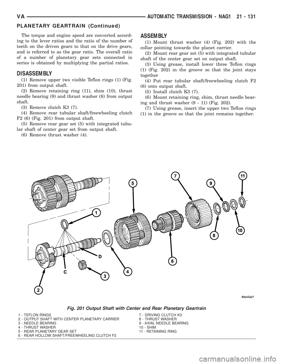
DISASSEMBLY
(1) Remove upper two visible Teflon rings (1) (Fig.
201) from output shaft.
(2) Remove retaining ring (11), shim (10), thrust
needle bearing (9) and thrust washer (8) from output
shaft.
(3) Remove clutch K3 (7).
(4) Remove rear tubular shaft/freewheeling clutch
F2 (6) (Fig. 201) from output shaft.
(5) Remove rear gear set (5) with integrated tubu-
lar shaft of center gear set from output shaft.
(6) Remove thrust washer (4).
ASSEMBLY
(1) Mount thrust washer (4) (Fig. 202) with the
collar pointing towards the planet carrier.
(2) Mount rear gear set (5) with integrated tubular
shaft of the center gear set on output shaft.
(3) Using grease, install lower three Teflon rings
(1) (Fig. 202) in the groove so that the joint stays
together
(4) Put rear tubular shaft/freewheeling clutch F2
(6) onto output shaft.
(5) Install clutch K3 (7).
(6) Mount retaining ring, shim, thrust needle bear-
ing and thrust washer (8 - 11) (Fig. 202).
(7) Using grease, insert the upper two Teflon rings
(1) in the groove so that the joint remains together.
Fig. 201 Output Shaft with Center and Rear Planetary Geartrain
1 - TEFLON RINGS 7 - DRIVING CLUTCH K3
2 - OUTPUT SHAFT WITH CENTER PLANETARY CARRIER 8 - THRUST WASHER
3 - NEEDLE BEARING 9 - AXIAL NEEDLE BEARING
4 - THRUST WASHER 10 - SHIM
5 - REAR PLANETARY GEAR SET 11 - RETAINING RING
6 - REAR HOLLOW SHAFT/FREEWHEELING CLUTCH F2
VAAUTOMATIC TRANSMISSION - NAG1 21 - 131
PLANETARY GEARTRAIN (Continued)
Page 1018 of 1232
IMPELLER
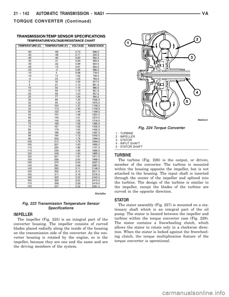
The impeller (Fig. 225) is an integral part of the
converter housing. The impeller consists of curved
blades placed radially along the inside of the housing
on the transmission side of the converter. As the con-
verter housing is rotated by the engine, so is the
impeller, because they are one and the same and are
the driving members of the system.
TURBINE
The turbine (Fig. 226) is the output, or driven,
member of the converter. The turbine is mounted
within the housing opposite the impeller, but is not
attached to the housing. The input shaft is inserted
through the center of the impeller and splined into
the turbine. The design of the turbine is similar to
the impeller, except the blades of the turbine are
curved in the opposite direction.
STATOR
The stator assembly (Fig. 227) is mounted on a sta-
tionary shaft which is an integral part of the oil
pump. The stator is located between the impeller and
turbine within the torque converter case (Fig. 228).
The stator contains a freewheeling clutch, which
allows the stator to rotate only in a clockwise direc-
tion. When the stator is locked against the freewheel-
ing clutch, the torque multiplication feature of the
torque converter is operational.Fig. 223 Transmission Temperature Sensor
Specifications
Fig. 224 Torque Converter
1 - TURBINE
2 - IMPELLER
3-STATOR
4 - INPUT SHAFT
5 - STATOR SHAFT
21 - 142 AUTOMATIC TRANSMISSION - NAG1VA
TORQUE CONVERTER (Continued)
Page 1021 of 1232
STATOR
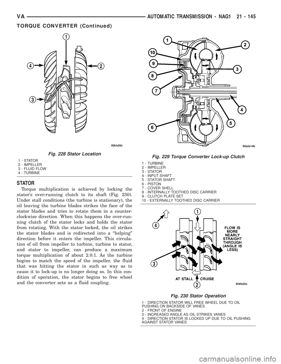
Torque multiplication is achieved by locking the
stator's over-running clutch to its shaft (Fig. 230).
Under stall conditions (the turbine is stationary), the
oil leaving the turbine blades strikes the face of the
stator blades and tries to rotate them in a counter-
clockwise direction. When this happens the over-run-
ning clutch of the stator locks and holds the stator
from rotating. With the stator locked, the oil strikes
the stator blades and is redirected into a ªhelpingº
direction before it enters the impeller. This circula-
tion of oil from impeller to turbine, turbine to stator,
and stator to impeller, can produce a maximum
torque multiplication of about 2.0:1. As the turbine
begins to match the speed of the impeller, the fluid
that was hitting the stator in such as way as to
cause it to lock-up is no longer doing so. In this con-
dition of operation, the stator begins to free wheel
and the converter acts as a fluid coupling.
Fig. 228 Stator Location
1-STATOR
2 - IMPELLER
3 - FLUID FLOW
4 - TURBINEFig. 229 Torque Converter Lock-up Clutch
1 - TURBINE
2 - IMPELLER
3-STATOR
4 - INPUT SHAFT
5 - STATOR SHAFT
6 - PISTON
7 - COVER SHELL
8 - INTERNALLY TOOTHED DISC CARRIER
9 - CLUTCH PLATE SET
10 - EXTERNALLY TOOTHED DISC CARRIER
Fig. 230 Stator Operation
1 - DIRECTION STATOR WILL FREE WHEEL DUE TO OIL
PUSHING ON BACKSIDE OF VANES
2 - FRONT OF ENGINE
3 - INCREASED ANGLE AS OIL STRIKES VANES
4 - DIRECTION STATOR IS LOCKED UP DUE TO OIL PUSHING
AGAINST STATOR VANES
VAAUTOMATIC TRANSMISSION - NAG1 21 - 145
TORQUE CONVERTER (Continued)