2005 MERCEDES-BENZ SPRINTER engine
[x] Cancel search: enginePage 299 of 1232
WIPER LINKAGE
DESCRIPTION
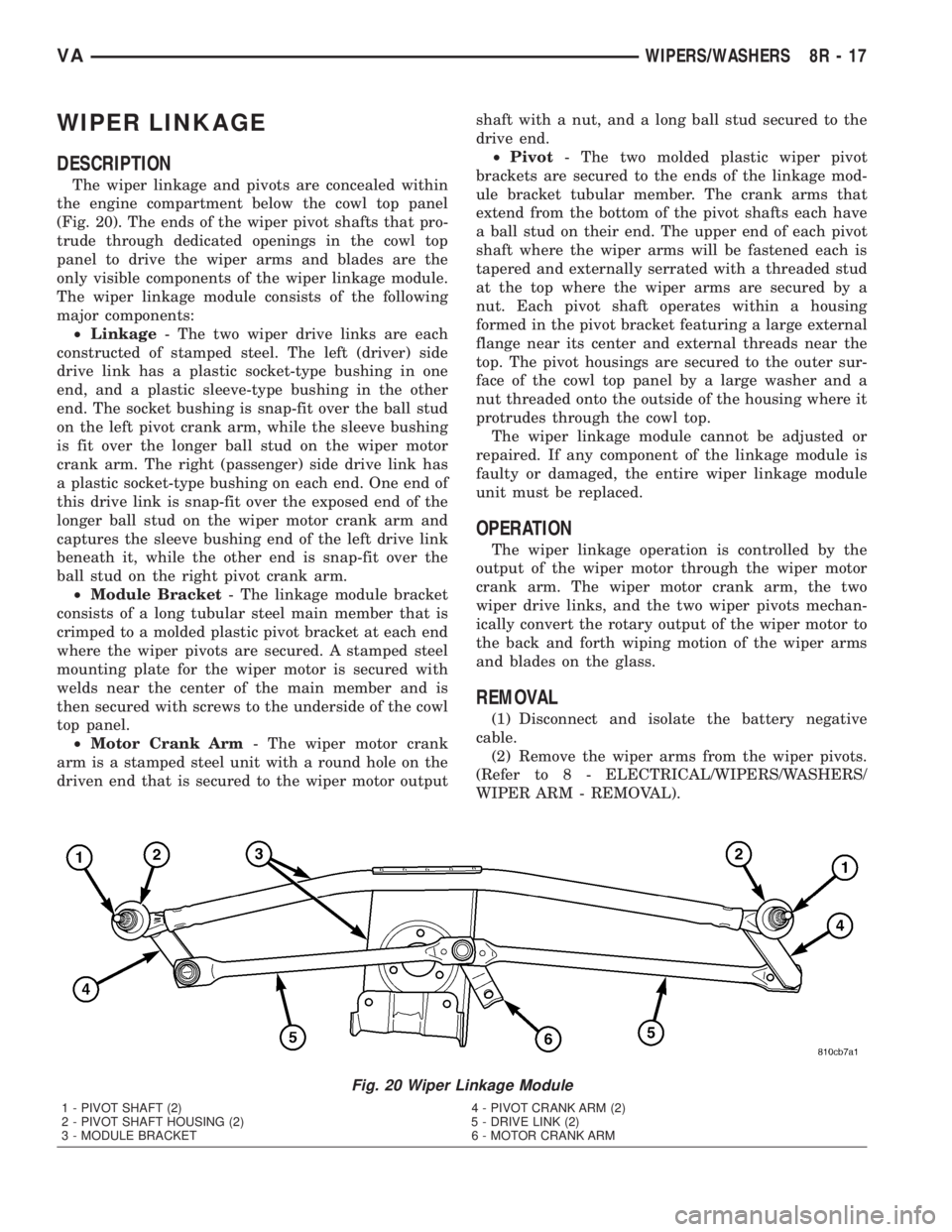
The wiper linkage and pivots are concealed within
the engine compartment below the cowl top panel
(Fig. 20). The ends of the wiper pivot shafts that pro-
trude through dedicated openings in the cowl top
panel to drive the wiper arms and blades are the
only visible components of the wiper linkage module.
The wiper linkage module consists of the following
major components:
²Linkage- The two wiper drive links are each
constructed of stamped steel. The left (driver) side
drive link has a plastic socket-type bushing in one
end, and a plastic sleeve-type bushing in the other
end. The socket bushing is snap-fit over the ball stud
on the left pivot crank arm, while the sleeve bushing
is fit over the longer ball stud on the wiper motor
crank arm. The right (passenger) side drive link has
a plastic socket-type bushing on each end. One end of
this drive link is snap-fit over the exposed end of the
longer ball stud on the wiper motor crank arm and
captures the sleeve bushing end of the left drive link
beneath it, while the other end is snap-fit over the
ball stud on the right pivot crank arm.
²Module Bracket- The linkage module bracket
consists of a long tubular steel main member that is
crimped to a molded plastic pivot bracket at each end
where the wiper pivots are secured. A stamped steel
mounting plate for the wiper motor is secured with
welds near the center of the main member and is
then secured with screws to the underside of the cowl
top panel.
²Motor Crank Arm- The wiper motor crank
arm is a stamped steel unit with a round hole on the
driven end that is secured to the wiper motor outputshaft with a nut, and a long ball stud secured to the
drive end.
²Pivot- The two molded plastic wiper pivot
brackets are secured to the ends of the linkage mod-
ule bracket tubular member. The crank arms that
extend from the bottom of the pivot shafts each have
a ball stud on their end. The upper end of each pivot
shaft where the wiper arms will be fastened each is
tapered and externally serrated with a threaded stud
at the top where the wiper arms are secured by a
nut. Each pivot shaft operates within a housing
formed in the pivot bracket featuring a large external
flange near its center and external threads near the
top. The pivot housings are secured to the outer sur-
face of the cowl top panel by a large washer and a
nut threaded onto the outside of the housing where it
protrudes through the cowl top.
The wiper linkage module cannot be adjusted or
repaired. If any component of the linkage module is
faulty or damaged, the entire wiper linkage module
unit must be replaced.
OPERATION
The wiper linkage operation is controlled by the
output of the wiper motor through the wiper motor
crank arm. The wiper motor crank arm, the two
wiper drive links, and the two wiper pivots mechan-
ically convert the rotary output of the wiper motor to
the back and forth wiping motion of the wiper arms
and blades on the glass.
REMOVAL
(1) Disconnect and isolate the battery negative
cable.
(2) Remove the wiper arms from the wiper pivots.
(Refer to 8 - ELECTRICAL/WIPERS/WASHERS/
WIPER ARM - REMOVAL).
Fig. 20 Wiper Linkage Module
1 - PIVOT SHAFT (2) 4 - PIVOT CRANK ARM (2)
2 - PIVOT SHAFT HOUSING (2) 5 - DRIVE LINK (2)
3 - MODULE BRACKET 6 - MOTOR CRANK ARM
VAWIPERS/WASHERS 8R - 17
Page 300 of 1232
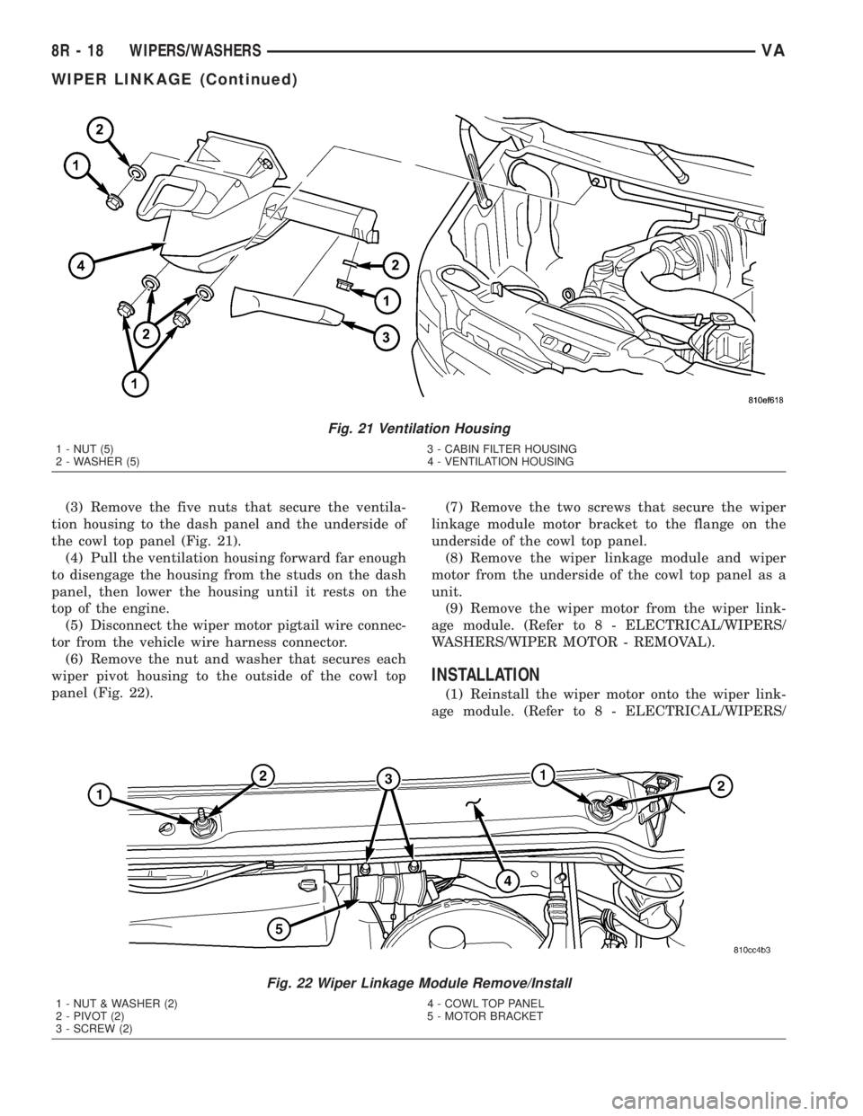
(3) Remove the five nuts that secure the ventila-
tion housing to the dash panel and the underside of
the cowl top panel (Fig. 21).
(4) Pull the ventilation housing forward far enough
to disengage the housing from the studs on the dash
panel, then lower the housing until it rests on the
top of the engine.
(5) Disconnect the wiper motor pigtail wire connec-
tor from the vehicle wire harness connector.
(6) Remove the nut and washer that secures each
wiper pivot housing to the outside of the cowl top
panel (Fig. 22).(7) Remove the two screws that secure the wiper
linkage module motor bracket to the flange on the
underside of the cowl top panel.
(8) Remove the wiper linkage module and wiper
motor from the underside of the cowl top panel as a
unit.
(9) Remove the wiper motor from the wiper link-
age module. (Refer to 8 - ELECTRICAL/WIPERS/
WASHERS/WIPER MOTOR - REMOVAL).
INSTALLATION
(1) Reinstall the wiper motor onto the wiper link-
age module. (Refer to 8 - ELECTRICAL/WIPERS/
Fig. 21 Ventilation Housing
1 - NUT (5) 3 - CABIN FILTER HOUSING
2 - WASHER (5) 4 - VENTILATION HOUSING
Fig. 22 Wiper Linkage Module Remove/Install
1 - NUT & WASHER (2) 4 - COWL TOP PANEL
2 - PIVOT (2) 5 - MOTOR BRACKET
3 - SCREW (2)
8R - 18 WIPERS/WASHERSVA
WIPER LINKAGE (Continued)
Page 301 of 1232
WASHERS/FRONT WIPER MOTOR -
INSTALLATION).
(2) Carefully position the wiper linkage module
and wiper motor to the underside of the cowl top
panel as a unit (Fig. 22).
(3) Install and tighten the two screws that secure
the wiper linkage module motor bracket to the flange
on the underside of the cowl top panel. Tighten the
screws to 6 N´m (50 in. lbs.).
(4) Install and tighten the nut and washer that
secures each wiper pivot housing to the outside of the
cowl top panel.
(5) Reconnect the wiper motor pigtail wire connec-
tor to the vehicle wire harness connector.
(6) Reinstall the ventilation housing onto the dash
panel and the underside of the cowl top panel (Fig.
21).
(7) Reinstall the wiper arms onto the wiper pivots.
(Refer to 8 - ELECTRICAL/WIPERS/WASHERS/
WIPER ARM - INSTALLATION).
(8) Reconnect the battery negative cable.
WIPER MOTOR
DESCRIPTION
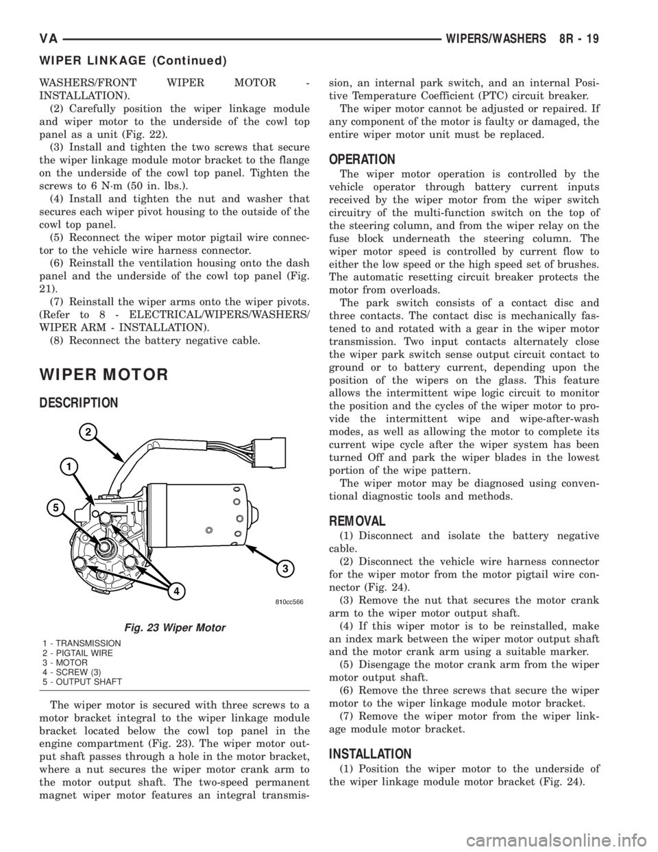
The wiper motor is secured with three screws to a
motor bracket integral to the wiper linkage module
bracket located below the cowl top panel in the
engine compartment (Fig. 23). The wiper motor out-
put shaft passes through a hole in the motor bracket,
where a nut secures the wiper motor crank arm to
the motor output shaft. The two-speed permanent
magnet wiper motor features an integral transmis-sion, an internal park switch, and an internal Posi-
tive Temperature Coefficient (PTC) circuit breaker.
The wiper motor cannot be adjusted or repaired. If
any component of the motor is faulty or damaged, the
entire wiper motor unit must be replaced.
OPERATION
The wiper motor operation is controlled by the
vehicle operator through battery current inputs
received by the wiper motor from the wiper switch
circuitry of the multi-function switch on the top of
the steering column, and from the wiper relay on the
fuse block underneath the steering column. The
wiper motor speed is controlled by current flow to
either the low speed or the high speed set of brushes.
The automatic resetting circuit breaker protects the
motor from overloads.
The park switch consists of a contact disc and
three contacts. The contact disc is mechanically fas-
tened to and rotated with a gear in the wiper motor
transmission. Two input contacts alternately close
the wiper park switch sense output circuit contact to
ground or to battery current, depending upon the
position of the wipers on the glass. This feature
allows the intermittent wipe logic circuit to monitor
the position and the cycles of the wiper motor to pro-
vide the intermittent wipe and wipe-after-wash
modes, as well as allowing the motor to complete its
current wipe cycle after the wiper system has been
turned Off and park the wiper blades in the lowest
portion of the wipe pattern.
The wiper motor may be diagnosed using conven-
tional diagnostic tools and methods.
REMOVAL
(1) Disconnect and isolate the battery negative
cable.
(2) Disconnect the vehicle wire harness connector
for the wiper motor from the motor pigtail wire con-
nector (Fig. 24).
(3) Remove the nut that secures the motor crank
arm to the wiper motor output shaft.
(4) If this wiper motor is to be reinstalled, make
an index mark between the wiper motor output shaft
and the motor crank arm using a suitable marker.
(5) Disengage the motor crank arm from the wiper
motor output shaft.
(6) Remove the three screws that secure the wiper
motor to the wiper linkage module motor bracket.
(7) Remove the wiper motor from the wiper link-
age module motor bracket.
INSTALLATION
(1) Position the wiper motor to the underside of
the wiper linkage module motor bracket (Fig. 24).
Fig. 23 Wiper Motor
1 - TRANSMISSION
2 - PIGTAIL WIRE
3 - MOTOR
4 - SCREW (3)
5 - OUTPUT SHAFT
VAWIPERS/WASHERS 8R - 19
WIPER LINKAGE (Continued)
Page 303 of 1232
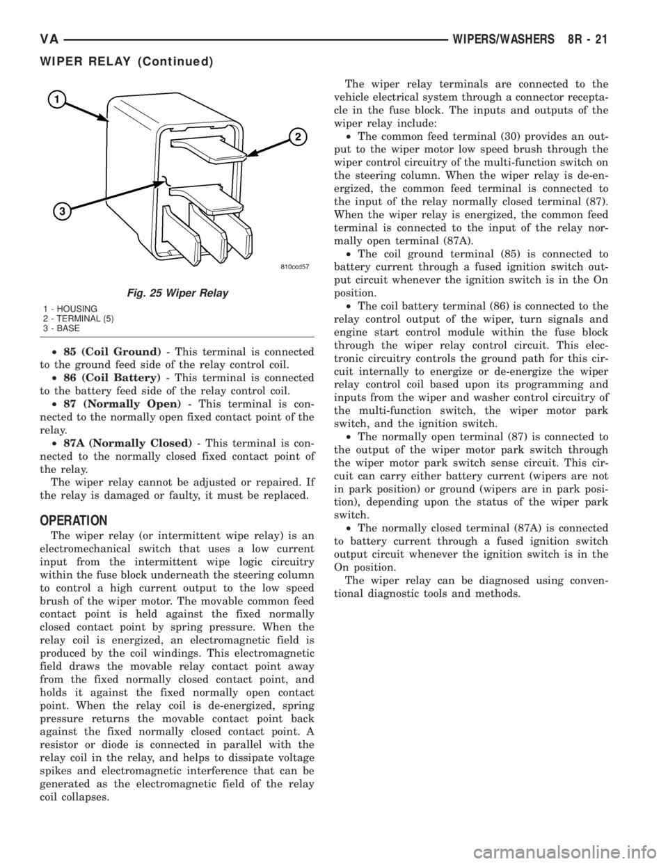
²85 (Coil Ground)- This terminal is connected
to the ground feed side of the relay control coil.
²86 (Coil Battery)- This terminal is connected
to the battery feed side of the relay control coil.
²87 (Normally Open)- This terminal is con-
nected to the normally open fixed contact point of the
relay.
²87A (Normally Closed)- This terminal is con-
nected to the normally closed fixed contact point of
the relay.
The wiper relay cannot be adjusted or repaired. If
the relay is damaged or faulty, it must be replaced.
OPERATION
The wiper relay (or intermittent wipe relay) is an
electromechanical switch that uses a low current
input from the intermittent wipe logic circuitry
within the fuse block underneath the steering column
to control a high current output to the low speed
brush of the wiper motor. The movable common feed
contact point is held against the fixed normally
closed contact point by spring pressure. When the
relay coil is energized, an electromagnetic field is
produced by the coil windings. This electromagnetic
field draws the movable relay contact point away
from the fixed normally closed contact point, and
holds it against the fixed normally open contact
point. When the relay coil is de-energized, spring
pressure returns the movable contact point back
against the fixed normally closed contact point. A
resistor or diode is connected in parallel with the
relay coil in the relay, and helps to dissipate voltage
spikes and electromagnetic interference that can be
generated as the electromagnetic field of the relay
coil collapses.The wiper relay terminals are connected to the
vehicle electrical system through a connector recepta-
cle in the fuse block. The inputs and outputs of the
wiper relay include:
²The common feed terminal (30) provides an out-
put to the wiper motor low speed brush through the
wiper control circuitry of the multi-function switch on
the steering column. When the wiper relay is de-en-
ergized, the common feed terminal is connected to
the input of the relay normally closed terminal (87).
When the wiper relay is energized, the common feed
terminal is connected to the input of the relay nor-
mally open terminal (87A).
²The coil ground terminal (85) is connected to
battery current through a fused ignition switch out-
put circuit whenever the ignition switch is in the On
position.
²The coil battery terminal (86) is connected to the
relay control output of the wiper, turn signals and
engine start control module within the fuse block
through the wiper relay control circuit. This elec-
tronic circuitry controls the ground path for this cir-
cuit internally to energize or de-energize the wiper
relay control coil based upon its programming and
inputs from the wiper and washer control circuitry of
the multi-function switch, the wiper motor park
switch, and the ignition switch.
²The normally open terminal (87) is connected to
the output of the wiper motor park switch through
the wiper motor park switch sense circuit. This cir-
cuit can carry either battery current (wipers are not
in park position) or ground (wipers are in park posi-
tion), depending upon the status of the wiper park
switch.
²The normally closed terminal (87A) is connected
to battery current through a fused ignition switch
output circuit whenever the ignition switch is in the
On position.
The wiper relay can be diagnosed using conven-
tional diagnostic tools and methods.
Fig. 25 Wiper Relay
1 - HOUSING
2 - TERMINAL (5)
3 - BASE
VAWIPERS/WASHERS 8R - 21
WIPER RELAY (Continued)
Page 311 of 1232
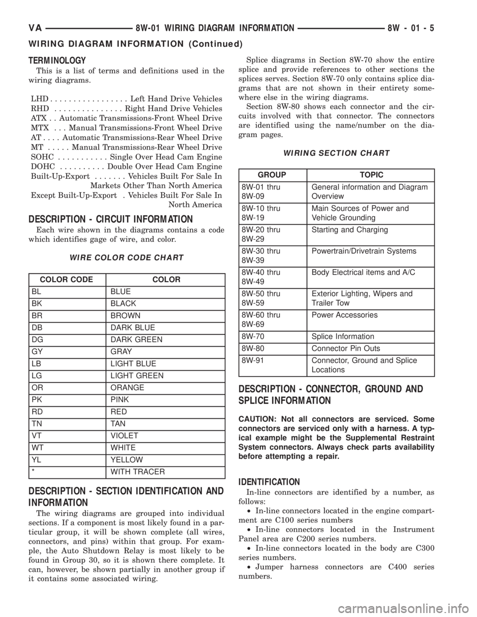
TERMINOLOGY
This is a list of terms and definitions used in the
wiring diagrams.
LHD.................Left Hand Drive Vehicles
RHD ...............Right Hand Drive Vehicles
ATX . . Automatic Transmissions-Front Wheel Drive
MTX . . . Manual Transmissions-Front Wheel Drive
AT....Automatic Transmissions-Rear Wheel Drive
MT .....Manual Transmissions-Rear Wheel Drive
SOHC...........Single Over Head Cam Engine
DOHC..........Double Over Head Cam Engine
Built-Up-Export....... Vehicles Built For Sale In
Markets Other Than North America
Except Built-Up-Export . Vehicles Built For Sale In
North America
DESCRIPTION - CIRCUIT INFORMATION
Each wire shown in the diagrams contains a code
which identifies gage of wire, and color.
WIRE COLOR CODE CHART
COLOR CODE COLOR
BL BLUE
BK BLACK
BR BROWN
DB DARK BLUE
DG DARK GREEN
GY GRAY
LB LIGHT BLUE
LG LIGHT GREEN
OR ORANGE
PK PINK
RD RED
TN TAN
VT VIOLET
WT WHITE
YL YELLOW
* WITH TRACER
DESCRIPTION - SECTION IDENTIFICATION AND
INFORMATION
The wiring diagrams are grouped into individual
sections. If a component is most likely found in a par-
ticular group, it will be shown complete (all wires,
connectors, and pins) within that group. For exam-
ple, the Auto Shutdown Relay is most likely to be
found in Group 30, so it is shown there complete. It
can, however, be shown partially in another group if
it contains some associated wiring.Splice diagrams in Section 8W-70 show the entire
splice and provide references to other sections the
splices serves. Section 8W-70 only contains splice dia-
grams that are not shown in their entirety some-
where else in the wiring diagrams.
Section 8W-80 shows each connector and the cir-
cuits involved with that connector. The connectors
are identified using the name/number on the dia-
gram pages.
WIRING SECTION CHART
GROUP TOPIC
8W-01 thru
8W-09General information and Diagram
Overview
8W-10 thru
8W-19Main Sources of Power and
Vehicle Grounding
8W-20 thru
8W-29Starting and Charging
8W-30 thru
8W-39Powertrain/Drivetrain Systems
8W-40 thru
8W-49Body Electrical items and A/C
8W-50 thru
8W-59Exterior Lighting, Wipers and
Trailer Tow
8W-60 thru
8W-69Power Accessories
8W-70 Splice Information
8W-80 Connector Pin Outs
8W-91 Connector, Ground and Splice
Locations
DESCRIPTION - CONNECTOR, GROUND AND
SPLICE INFORMATION
CAUTION: Not all connectors are serviced. Some
connectors are serviced only with a harness. A typ-
ical example might be the Supplemental Restraint
System connectors. Always check parts availability
before attempting a repair.
IDENTIFICATION
In-line connectors are identified by a number, as
follows:
²In-line connectors located in the engine compart-
ment are C100 series numbers
²In-line connectors located in the Instrument
Panel area are C200 series numbers.
²In-line connectors located in the body are C300
series numbers.
²Jumper harness connectors are C400 series
numbers.
VA8W-01 WIRING DIAGRAM INFORMATION 8W - 01 - 5
WIRING DIAGRAM INFORMATION (Continued)
Page 312 of 1232
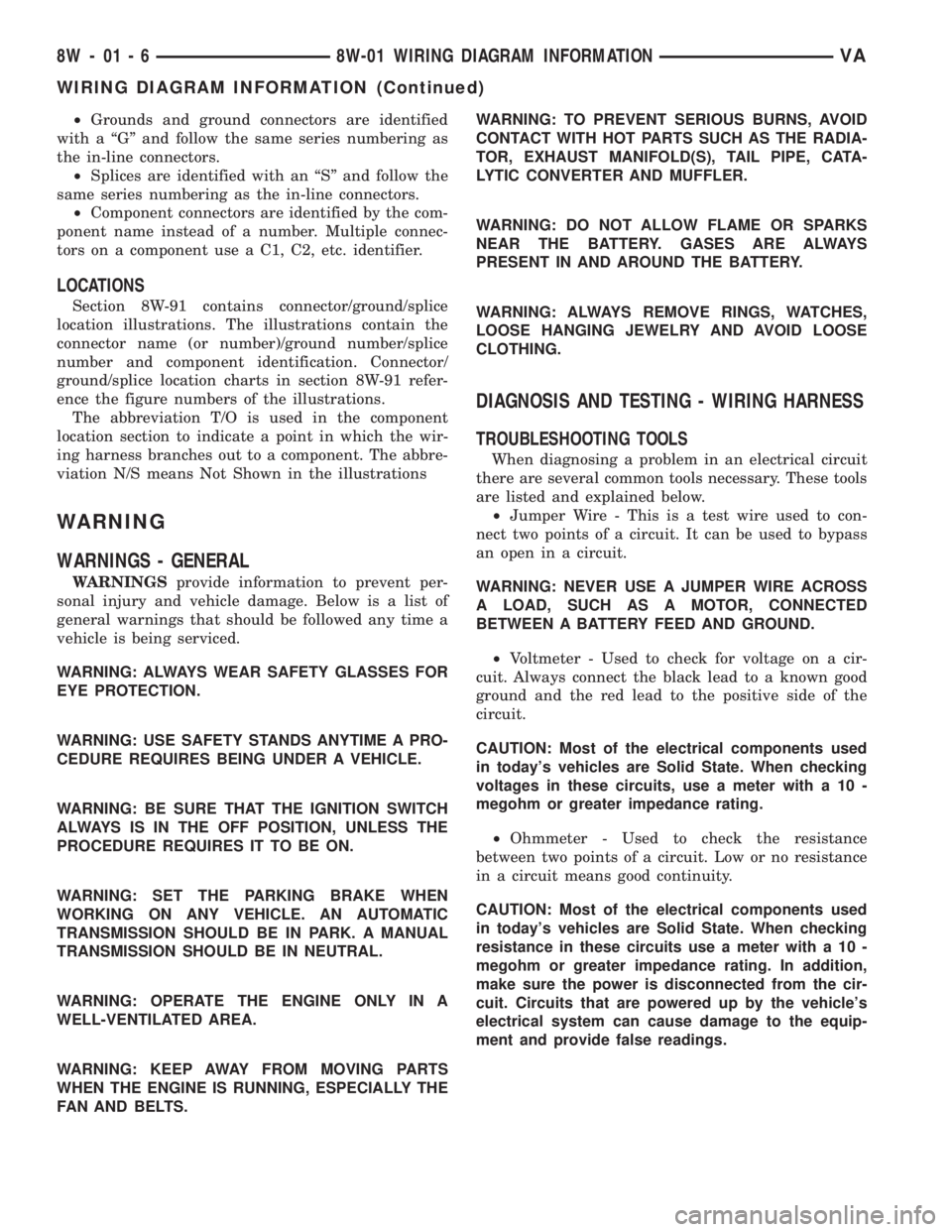
²Grounds and ground connectors are identified
with a ªGº and follow the same series numbering as
the in-line connectors.
²Splices are identified with an ªSº and follow the
same series numbering as the in-line connectors.
²Component connectors are identified by the com-
ponent name instead of a number. Multiple connec-
tors on a component use a C1, C2, etc. identifier.
LOCATIONS
Section 8W-91 contains connector/ground/splice
location illustrations. The illustrations contain the
connector name (or number)/ground number/splice
number and component identification. Connector/
ground/splice location charts in section 8W-91 refer-
ence the figure numbers of the illustrations.
The abbreviation T/O is used in the component
location section to indicate a point in which the wir-
ing harness branches out to a component. The abbre-
viation N/S means Not Shown in the illustrations
WARNING
WARNINGS - GENERAL
WARNINGSprovide information to prevent per-
sonal injury and vehicle damage. Below is a list of
general warnings that should be followed any time a
vehicle is being serviced.
WARNING: ALWAYS WEAR SAFETY GLASSES FOR
EYE PROTECTION.
WARNING: USE SAFETY STANDS ANYTIME A PRO-
CEDURE REQUIRES BEING UNDER A VEHICLE.
WARNING: BE SURE THAT THE IGNITION SWITCH
ALWAYS IS IN THE OFF POSITION, UNLESS THE
PROCEDURE REQUIRES IT TO BE ON.
WARNING: SET THE PARKING BRAKE WHEN
WORKING ON ANY VEHICLE. AN AUTOMATIC
TRANSMISSION SHOULD BE IN PARK. A MANUAL
TRANSMISSION SHOULD BE IN NEUTRAL.
WARNING: OPERATE THE ENGINE ONLY IN A
WELL-VENTILATED AREA.
WARNING: KEEP AWAY FROM MOVING PARTS
WHEN THE ENGINE IS RUNNING, ESPECIALLY THE
FAN AND BELTS.WARNING: TO PREVENT SERIOUS BURNS, AVOID
CONTACT WITH HOT PARTS SUCH AS THE RADIA-
TOR, EXHAUST MANIFOLD(S), TAIL PIPE, CATA-
LYTIC CONVERTER AND MUFFLER.
WARNING: DO NOT ALLOW FLAME OR SPARKS
NEAR THE BATTERY. GASES ARE ALWAYS
PRESENT IN AND AROUND THE BATTERY.
WARNING: ALWAYS REMOVE RINGS, WATCHES,
LOOSE HANGING JEWELRY AND AVOID LOOSE
CLOTHING.
DIAGNOSIS AND TESTING - WIRING HARNESS
TROUBLESHOOTING TOOLS
When diagnosing a problem in an electrical circuit
there are several common tools necessary. These tools
are listed and explained below.
²Jumper Wire - This is a test wire used to con-
nect two points of a circuit. It can be used to bypass
an open in a circuit.
WARNING: NEVER USE A JUMPER WIRE ACROSS
A LOAD, SUCH AS A MOTOR, CONNECTED
BETWEEN A BATTERY FEED AND GROUND.
²Voltmeter - Used to check for voltage on a cir-
cuit. Always connect the black lead to a known good
ground and the red lead to the positive side of the
circuit.
CAUTION: Most of the electrical components used
in today's vehicles are Solid State. When checking
voltages in these circuits, use a meter with a 10 -
megohm or greater impedance rating.
²Ohmmeter - Used to check the resistance
between two points of a circuit. Low or no resistance
in a circuit means good continuity.
CAUTION: Most of the electrical components used
in today's vehicles are Solid State. When checking
resistance in these circuits use a meter with a 10 -
megohm or greater impedance rating. In addition,
make sure the power is disconnected from the cir-
cuit. Circuits that are powered up by the vehicle's
electrical system can cause damage to the equip-
ment and provide false readings.
8W - 01 - 6 8W-01 WIRING DIAGRAM INFORMATIONVA
WIRING DIAGRAM INFORMATION (Continued)
Page 317 of 1232
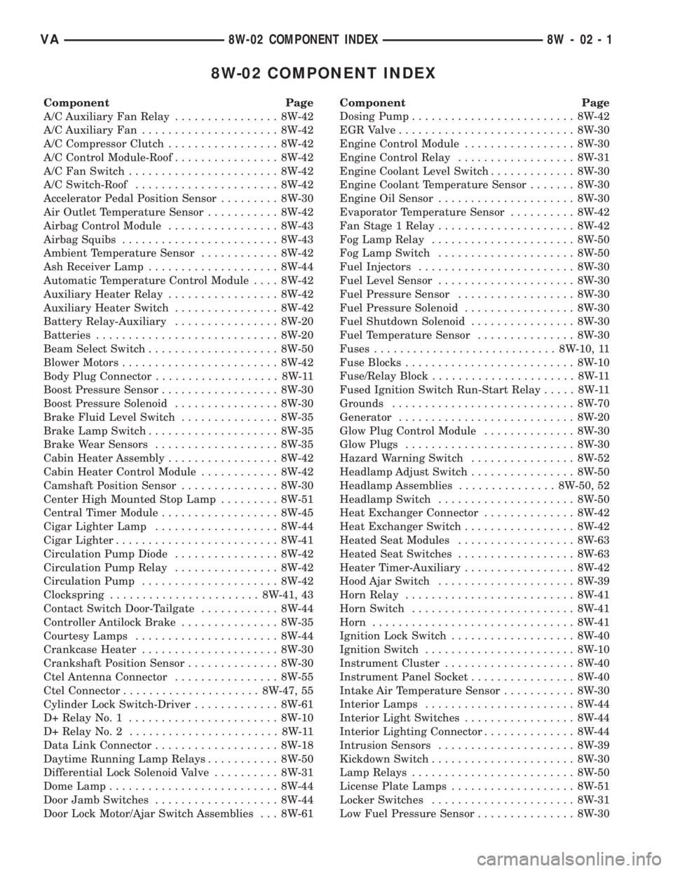
8W-02 COMPONENT INDEX
Component Page
A/C Auxiliary Fan Relay................ 8W-42
A/C Auxiliary Fan..................... 8W-42
A/C Compressor Clutch................. 8W-42
A/C Control Module-Roof................ 8W-42
A/C Fan Switch....................... 8W-42
A/C Switch-Roof...................... 8W-42
Accelerator Pedal Position Sensor......... 8W-30
Air Outlet Temperature Sensor........... 8W-42
Airbag Control Module................. 8W-43
Airbag Squibs........................ 8W-43
Ambient Temperature Sensor............ 8W-42
Ash Receiver Lamp.................... 8W-44
Automatic Temperature Control Module.... 8W-42
Auxiliary Heater Relay................. 8W-42
Auxiliary Heater Switch................ 8W-42
Battery Relay-Auxiliary................ 8W-20
Batteries............................ 8W-20
Beam Select Switch.................... 8W-50
Blower Motors........................ 8W-42
Body Plug Connector................... 8W-11
Boost Pressure Sensor.................. 8W-30
Boost Pressure Solenoid................ 8W-30
Brake Fluid Level Switch............... 8W-35
Brake Lamp Switch.................... 8W-35
Brake Wear Sensors................... 8W-35
Cabin Heater Assembly................. 8W-42
Cabin Heater Control Module............ 8W-42
Camshaft Position Sensor............... 8W-30
Center High Mounted Stop Lamp......... 8W-51
Central Timer Module.................. 8W-45
Cigar Lighter Lamp................... 8W-44
Cigar Lighter......................... 8W-41
Circulation Pump Diode................ 8W-42
Circulation Pump Relay................ 8W-42
Circulation Pump..................... 8W-42
Clockspring....................... 8W-41, 43
Contact Switch Door-Tailgate............ 8W-44
Controller Antilock Brake............... 8W-35
Courtesy Lamps...................... 8W-44
Crankcase Heater..................... 8W-30
Crankshaft Position Sensor.............. 8W-30
Ctel Antenna Connector................ 8W-55
Ctel Connector..................... 8W-47, 55
Cylinder Lock Switch-Driver............. 8W-61
D+ Relay No. 1....................... 8W-10
D+ Relay No. 2....................... 8W-11
Data Link Connector................... 8W-18
Daytime Running Lamp Relays........... 8W-50
Differential Lock Solenoid Valve.......... 8W-31
Dome Lamp.......................... 8W-44
Door Jamb Switches................... 8W-44
Door Lock Motor/Ajar Switch Assemblies . . . 8W-61Component Page
Dosing Pump......................... 8W-42
EGR Valve........................... 8W-30
Engine Control Module................. 8W-30
Engine Control Relay.................. 8W-31
Engine Coolant Level Switch............. 8W-30
Engine Coolant Temperature Sensor....... 8W-30
Engine Oil Sensor..................... 8W-30
Evaporator Temperature Sensor.......... 8W-42
Fan Stage 1 Relay..................... 8W-42
Fog Lamp Relay...................... 8W-50
Fog Lamp Switch..................... 8W-50
Fuel Injectors........................ 8W-30
Fuel Level Sensor..................... 8W-30
Fuel Pressure Sensor.................. 8W-30
Fuel Pressure Solenoid................. 8W-30
Fuel Shutdown Solenoid................ 8W-30
Fuel Temperature Sensor............... 8W-30
Fuses............................ 8W-10, 11
Fuse Blocks.......................... 8W-10
Fuse/Relay Block...................... 8W-11
Fused Ignition Switch Run-Start Relay..... 8W-11
Grounds............................ 8W-70
Generator........................... 8W-20
Glow Plug Control Module.............. 8W-30
Glow Plugs.......................... 8W-30
Hazard Warning Switch................ 8W-52
Headlamp Adjust Switch................ 8W-50
Headlamp Assemblies............... 8W-50, 52
Headlamp Switch..................... 8W-50
Heat Exchanger Connector.............. 8W-42
Heat Exchanger Switch................. 8W-42
Heated Seat Modules.................. 8W-63
Heated Seat Switches.................. 8W-63
Heater Timer-Auxiliary................. 8W-42
Hood Ajar Switch..................... 8W-39
Horn Relay.......................... 8W-41
Horn Switch......................... 8W-41
Horn............................... 8W-41
Ignition Lock Switch................... 8W-40
Ignition Switch....................... 8W-10
Instrument Cluster.................... 8W-40
Instrument Panel Socket................ 8W-40
Intake Air Temperature Sensor........... 8W-30
Interior Lamps....................... 8W-44
Interior Light Switches................. 8W-44
Interior Lighting Connector.............. 8W-44
Intrusion Sensors..................... 8W-39
Kickdown Switch...................... 8W-30
Lamp Relays......................... 8W-50
License Plate Lamps................... 8W-51
Locker Switches...................... 8W-31
Low Fuel Pressure Sensor............... 8W-30
VA8W-02 COMPONENT INDEX 8W - 02 - 1
Page 318 of 1232
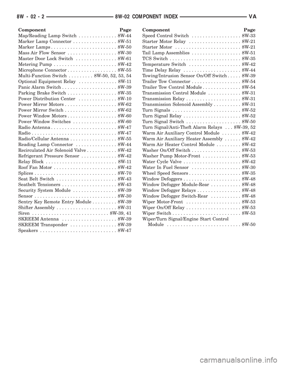
Component Page
Map/Reading Lamp Switch.............. 8W-44
Marker Lamp Connector................ 8W-51
Marker Lamps........................ 8W-50
Mass Air Flow Sensor.................. 8W-30
Master Door Lock Switch............... 8W-61
Metering Pump....................... 8W-42
Microphone Connector.................. 8W-55
Multi-Function Switch......... 8W-50, 52, 53, 54
Optional Equipment Relay.............. 8W-11
Panic Alarm Switch.................... 8W-39
Parking Brake Switch.................. 8W-35
Power Distribution Center.............. 8W-10
Power Mirror Motors................... 8W-62
Power Mirror Switch................... 8W-62
Power Window Motors.................. 8W-60
Power Window Switches................ 8W-60
Radio Antenna........................ 8W-47
Radio............................... 8W-47
Radio/Cellular Antenna................. 8W-55
Reading Lamp Connector............... 8W-44
Recirculated Air Solenoid Valve........... 8W-42
Refrigerant Pressure Sensor............. 8W-42
Relay Block.......................... 8W-11
Roof Fan Motor....................... 8W-42
Splices.............................. 8W-70
Seat Belt Switch...................... 8W-43
Seatbelt Tensioners.................... 8W-43
Security System Module................ 8W-39
Sensor.............................. 8W-30
Sentry Key Remote Entry Module......... 8W-39
Shifter Assembly...................... 8W-31
Siren............................ 8W-39, 41
SKREEM Antenna.................... 8W-39
SKREEM Transponder................. 8W-39
Speakers............................ 8W-47Component Page
Speed Control Switch.................. 8W-33
Starter Motor Relay................... 8W-21
Starter Motor........................ 8W-21
Tail Lamp Assemblies.................. 8W-51
TCS Switch.......................... 8W-35
Temperature Switch................... 8W-42
Time Delay Relay..................... 8W-44
Towing/Intrusion Sensor On/Off Switch..... 8W-39
Trailer Tow Connector.................. 8W-54
Trailer Tow Control Module.............. 8W-54
Transmission Control Module............ 8W-31
Transmission Relay.................... 8W-31
Transmission Solenoid Assembly.......... 8W-31
Turn Signals......................... 8W-52
Turn Signal Relay..................... 8W-52
Turn Signal Switch.................... 8W-50
Turn Signal/Anti-Theft Alarm Relays . . . 8W-39, 52
Warm Air Auxiliary Control Module....... 8W-42
Warm Air Auxiliary Heater Assembly...... 8W-42
Warm Air Heater Control Module......... 8W-42
Washer On/Off Switch.................. 8W-53
Washer Pump Motor-Front.............. 8W-53
Water Cycle Valve..................... 8W-42
Water In Fuel Sensor.................. 8W-30
Wheel Speed Sensors................... 8W-35
Window Defoggers..................... 8W-48
Window Defogger Module-Rear........... 8W-48
Window Defogger Relays................ 8W-48
Window Defogger Switch-Rear........... 8W-48
Wiper Motor-Front.................... 8W-53
Wiper On/Off Relay.................... 8W-53
Wiper Switch......................... 8W-53
Wiper/Turn Signal/Engine Start Control
Module........................... 8W-50
8W - 02 - 2 8W-02 COMPONENT INDEXVA