2005 MERCEDES-BENZ SPRINTER warning
[x] Cancel search: warningPage 792 of 1232
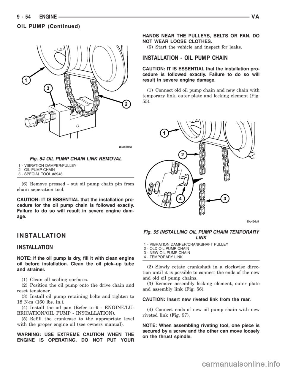
(6) Remove pressed - out oil pump chain pin from
chain seperation tool.
CAUTION: IT IS ESSENTIAL that the installation pro-
cedure for the oil pump chain is followed exactly.
Failure to do so will result in severe engine dam-
age.
INSTALLATION
INSTALLATION
NOTE: If the oil pump is dry, fill it with clean engine
oil before installation. Clean the oil pick±up tube
and strainer.
(1) Clean all sealing surfaces.
(2) Position the oil pump onto the drive chain and
reset tensioner.
(3) Install oil pump retaining bolts and tighten to
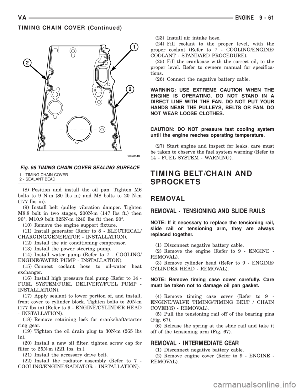
18 N´m (160 lbs. in.).
(4) Install the oil pan (Refer to 9 - ENGINE/LU-
BRICATION/OIL PUMP - INSTALLATION).
(5) Refill the crankcase to the appropriate level
with the proper engine oil (see owners manual).
WARNING: USE EXTREME CAUTION WHEN THE
ENGINE IS OPERATING. DO NOT PUT YOURHANDS NEAR THE PULLEYS, BELTS OR FAN. DO
NOT WEAR LOOSE CLOTHES.
(6) Start the vehicle and inspect for leaks.
INSTALLATION - OIL PUMP CHAIN
CAUTION: IT IS ESSENTIAL that the installation pro-
cedure is followed exactly. Failure to do so will
result in severe engine damage.
(1) Connect old oil pump chain and new chain with
temporary link, outer plate and locking element (Fig.
55).
(2) Slowly rotate crankshaft in a clockwise direc-
tion until it is possible to connect the ends of the new
and old oil pump chains.
(3) Remove assembly locking element, outer plate
and assembly link (Fig. 56).
CAUTION: Insert new riveted link from the rear.
(4) Connect ends of new oil pump chain with new
riveted link (Fig. 57).
NOTE: When assembling riveting tool, one piece is
secured by a screw and the other can move loosely
on the thrust spindle.
Fig. 54 OIL PUMP CHAIN LINK REMOVAL
1 - VIBRATION DAMPER/PULLEY
2 - OIL PUMP CHAIN
3 - SPECIAL TOOL #8948
Fig. 55 INSTALLING OIL PUMP CHAIN TEMPORARY
LINK
1 - VIBRATION DAMPER/CRANKSHAFT PULLEY
2 - OLD OIL PUMP CHAIN
3 - NEW OIL PUMP CHAIN
4 - TEMPORARY LINK
9 - 54 ENGINEVA
OIL PUMP (Continued)
Page 794 of 1232
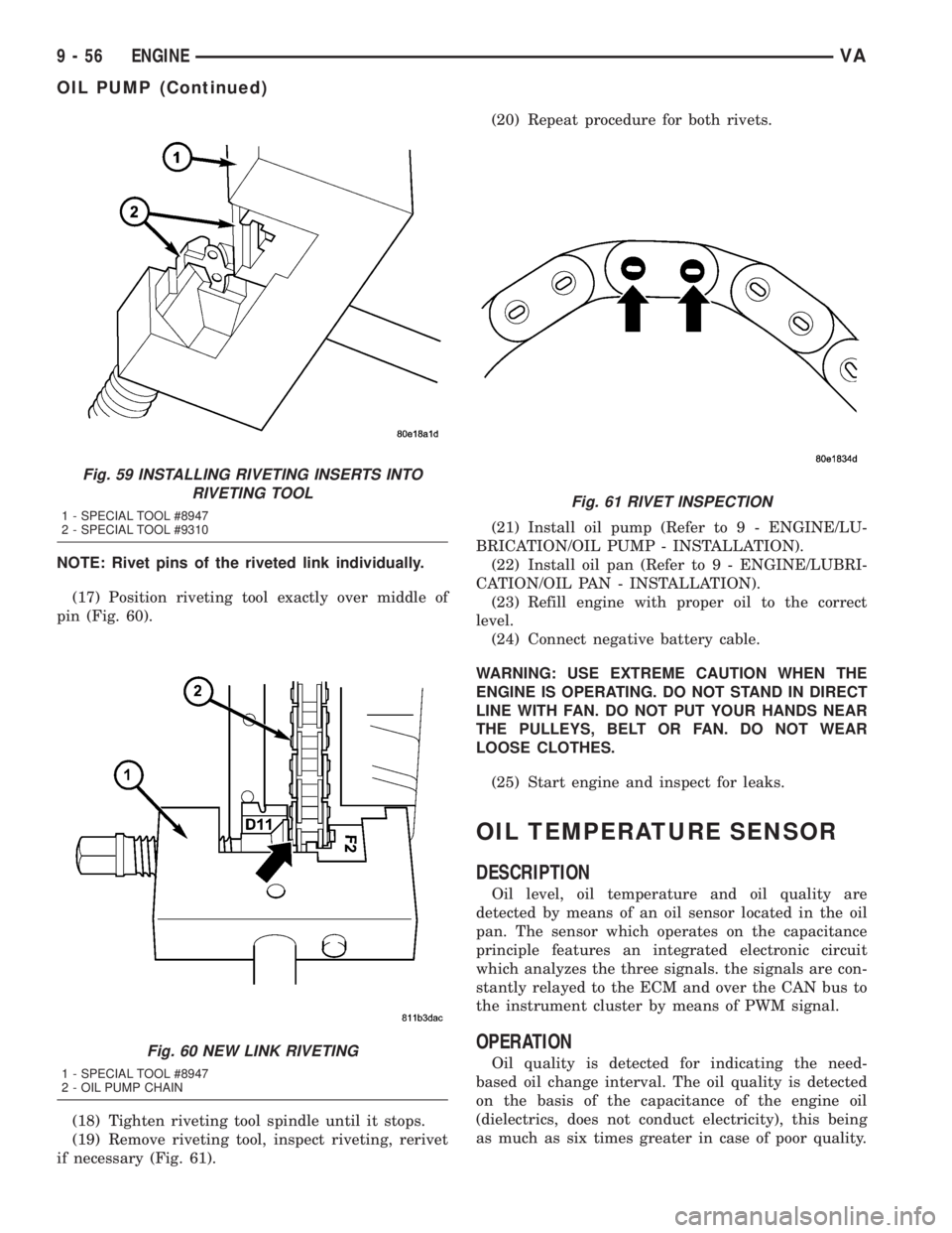
NOTE: Rivet pins of the riveted link individually.
(17) Position riveting tool exactly over middle of
pin (Fig. 60).
(18) Tighten riveting tool spindle until it stops.
(19) Remove riveting tool, inspect riveting, rerivet
if necessary (Fig. 61).(20) Repeat procedure for both rivets.
(21) Install oil pump (Refer to 9 - ENGINE/LU-
BRICATION/OIL PUMP - INSTALLATION).
(22) Install oil pan (Refer to 9 - ENGINE/LUBRI-
CATION/OIL PAN - INSTALLATION).
(23) Refill engine with proper oil to the correct
level.
(24) Connect negative battery cable.
WARNING: USE EXTREME CAUTION WHEN THE
ENGINE IS OPERATING. DO NOT STAND IN DIRECT
LINE WITH FAN. DO NOT PUT YOUR HANDS NEAR
THE PULLEYS, BELT OR FAN. DO NOT WEAR
LOOSE CLOTHES.
(25) Start engine and inspect for leaks.
OIL TEMPERATURE SENSOR
DESCRIPTION
Oil level, oil temperature and oil quality are
detected by means of an oil sensor located in the oil
pan. The sensor which operates on the capacitance
principle features an integrated electronic circuit
which analyzes the three signals. the signals are con-
stantly relayed to the ECM and over the CAN bus to
the instrument cluster by means of PWM signal.
OPERATION
Oil quality is detected for indicating the need-
based oil change interval. The oil quality is detected
on the basis of the capacitance of the engine oil
(dielectrics, does not conduct electricity), this being
as much as six times greater in case of poor quality.
Fig. 59 INSTALLING RIVETING INSERTS INTO
RIVETING TOOL
1 - SPECIAL TOOL #8947
2 - SPECIAL TOOL #9310
Fig. 60 NEW LINK RIVETING
1 - SPECIAL TOOL #8947
2 - OIL PUMP CHAIN
Fig. 61 RIVET INSPECTION
9 - 56 ENGINEVA
OIL PUMP (Continued)
Page 795 of 1232
Oil level and oil quality are separate of each other.
The information is first of all compensated in the
ECM before being transmitted over the CAN bus.
Faults at the oil sensor are detected by the ECM
and entered into fault memory. The voltage for the
oil sensor (approx.5V) is supplied by the ECM.
REMOVAL
(1) Disconnect the negative battery cable.
(2) Raise and support the vehicle.
(3) Drain engine oil into a suitable, and appropri-
ately marked container.
(4) Remove engine mount to chassis nuts.
(5) Lower vehicle and install engine support.
(6) Raise engine until the weight of the engine no
longer rests on the engine mounts.
(7) Raise and support the vehicle.
(8) Detach the front stabilizer bar at the front axle
and rotate it downward.
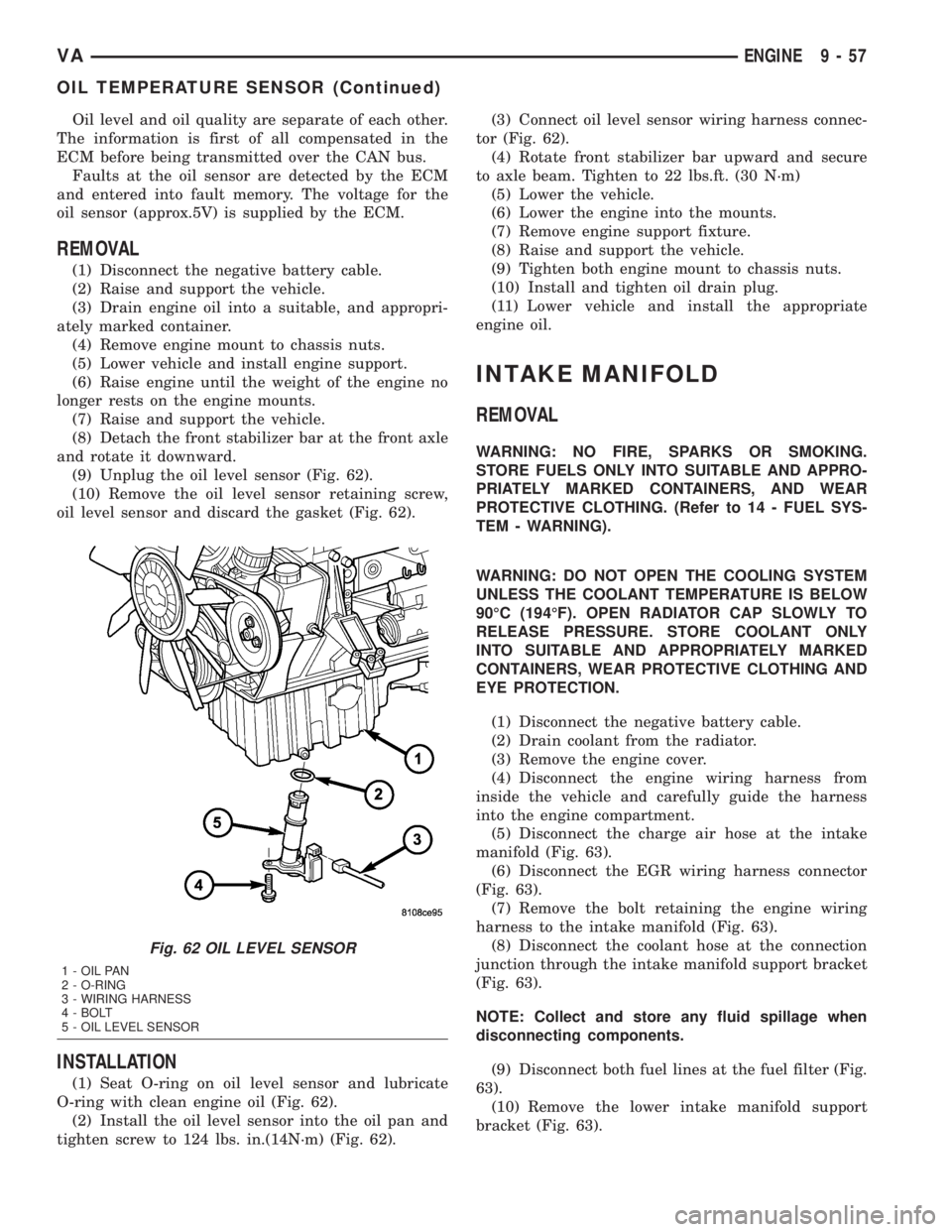
(9) Unplug the oil level sensor (Fig. 62).
(10) Remove the oil level sensor retaining screw,
oil level sensor and discard the gasket (Fig. 62).
INSTALLATION
(1) Seat O-ring on oil level sensor and lubricate
O-ring with clean engine oil (Fig. 62).
(2) Install the oil level sensor into the oil pan and
tighten screw to 124 lbs. in.(14N´m) (Fig. 62).(3) Connect oil level sensor wiring harness connec-
tor (Fig. 62).
(4) Rotate front stabilizer bar upward and secure
to axle beam. Tighten to 22 lbs.ft. (30 N´m)
(5) Lower the vehicle.
(6) Lower the engine into the mounts.
(7) Remove engine support fixture.
(8) Raise and support the vehicle.
(9) Tighten both engine mount to chassis nuts.
(10) Install and tighten oil drain plug.
(11) Lower vehicle and install the appropriate
engine oil.
INTAKE MANIFOLD
REMOVAL
WARNING: NO FIRE, SPARKS OR SMOKING.
STORE FUELS ONLY INTO SUITABLE AND APPRO-
PRIATELY MARKED CONTAINERS, AND WEAR
PROTECTIVE CLOTHING. (Refer to 14 - FUEL SYS-
TEM - WARNING).
WARNING: DO NOT OPEN THE COOLING SYSTEM
UNLESS THE COOLANT TEMPERATURE IS BELOW
90ÉC (194ÉF). OPEN RADIATOR CAP SLOWLY TO
RELEASE PRESSURE. STORE COOLANT ONLY
INTO SUITABLE AND APPROPRIATELY MARKED
CONTAINERS, WEAR PROTECTIVE CLOTHING AND
EYE PROTECTION.
(1) Disconnect the negative battery cable.
(2) Drain coolant from the radiator.
(3) Remove the engine cover.
(4) Disconnect the engine wiring harness from
inside the vehicle and carefully guide the harness
into the engine compartment.
(5) Disconnect the charge air hose at the intake
manifold (Fig. 63).
(6) Disconnect the EGR wiring harness connector
(Fig. 63).
(7) Remove the bolt retaining the engine wiring
harness to the intake manifold (Fig. 63).
(8) Disconnect the coolant hose at the connection
junction through the intake manifold support bracket
(Fig. 63).
NOTE: Collect and store any fluid spillage when
disconnecting components.
(9) Disconnect both fuel lines at the fuel filter (Fig.
63).
(10) Remove the lower intake manifold support
bracket (Fig. 63).
Fig. 62 OIL LEVEL SENSOR
1 - OIL PAN
2 - O-RING
3 - WIRING HARNESS
4 - BOLT
5 - OIL LEVEL SENSOR
VAENGINE 9 - 57
OIL TEMPERATURE SENSOR (Continued)
Page 797 of 1232
(7) Install the right intake manifold support brack-
ets. Tighten the bolts to 14 N´m (124 lbs. in.) (Fig.
63).
(8) Install the lower intake manifold support
bracket. Tighten bolts to 20 N´m (177 lbs. in.) (Fig.
63).
(9) Connect both fuel lines to fuel filter assembly
(Refer to 14 - FUEL SYSTEM/FUEL DELIVERY/
FUEL FILTER - INSTALLATION).
(10) Connect the coolant hose at the connection
junction above the lower intake manifold support
bracket (Fig. 63).
(11) Secure the engine wiring harness and cable
duct to the intake manifold (Fig. 63).
(12) Connect the EGR wiring harness connector
(Fig. 63).
(13) Connect the charge air hose to the intake
manifold (Fig. 63).
(14) Carefully route the engine wiring harness
through and into the passenger compartment and
reconnect.
(15) Install the engine cover.
(16) Fill the cooling system.
(17) Connect the negative battery cable.
(18) Start the engine and inspect for leaks. Care
must be taken to observe the fuel system warnin-
g.(Refer to 14 - FUEL SYSTEM - WARNING).
EXHAUST MANIFOLD
REMOVAL
(1) Remove the turbocharger (Refer to 11 -
EXHAUST SYSTEM/TURBOCHARGER SYSTEM/
TURBOCHARGER - REMOVAL).
(2) Remove the self locking exhaust manifold nuts
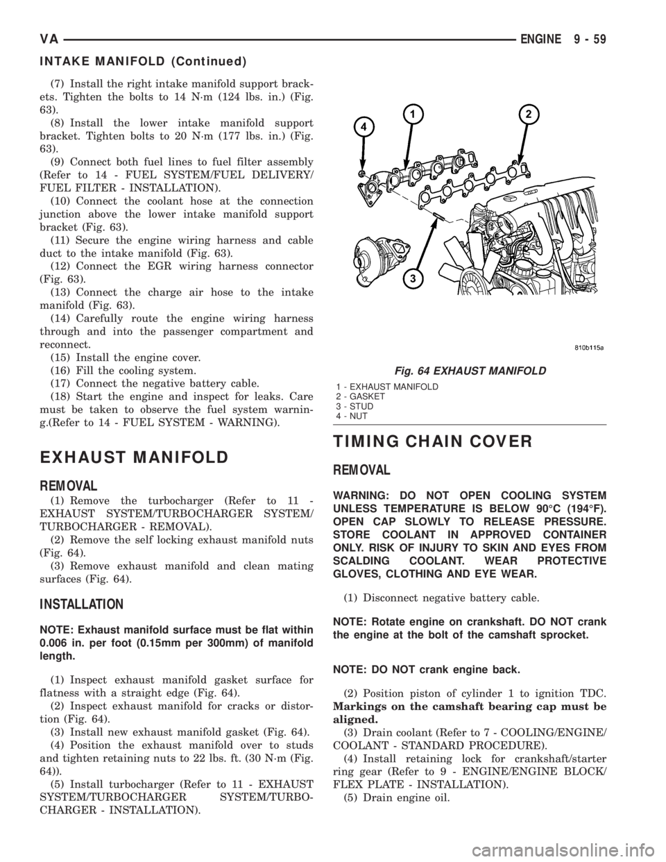
(Fig. 64).
(3) Remove exhaust manifold and clean mating
surfaces (Fig. 64).
INSTALLATION
NOTE: Exhaust manifold surface must be flat within
0.006 in. per foot (0.15mm per 300mm) of manifold
length.
(1) Inspect exhaust manifold gasket surface for
flatness with a straight edge (Fig. 64).
(2) Inspect exhaust manifold for cracks or distor-
tion (Fig. 64).
(3) Install new exhaust manifold gasket (Fig. 64).
(4) Position the exhaust manifold over to studs
and tighten retaining nuts to 22 lbs. ft. (30 N´m (Fig.
64)).
(5) Install turbocharger (Refer to 11 - EXHAUST
SYSTEM/TURBOCHARGER SYSTEM/TURBO-
CHARGER - INSTALLATION).
TIMING CHAIN COVER
REMOVAL
WARNING: DO NOT OPEN COOLING SYSTEM
UNLESS TEMPERATURE IS BELOW 90ÉC (194ÉF).
OPEN CAP SLOWLY TO RELEASE PRESSURE.
STORE COOLANT IN APPROVED CONTAINER
ONLY. RISK OF INJURY TO SKIN AND EYES FROM
SCALDING COOLANT. WEAR PROTECTIVE
GLOVES, CLOTHING AND EYE WEAR.
(1) Disconnect negative battery cable.
NOTE: Rotate engine on crankshaft. DO NOT crank
the engine at the bolt of the camshaft sprocket.
NOTE: DO NOT crank engine back.
(2) Position piston of cylinder 1 to ignition TDC.
Markings on the camshaft bearing cap must be
aligned.
(3) Drain coolant (Refer to 7 - COOLING/ENGINE/
COOLANT - STANDARD PROCEDURE).
(4) Install retaining lock for crankshaft/starter
ring gear (Refer to 9 - ENGINE/ENGINE BLOCK/
FLEX PLATE - INSTALLATION).
(5) Drain engine oil.
Fig. 64 EXHAUST MANIFOLD
1 - EXHAUST MANIFOLD
2 - GASKET
3 - STUD
4 - NUT
VAENGINE 9 - 59
INTAKE MANIFOLD (Continued)
Page 799 of 1232
(8) Position and install the oil pan. Tighten M6
bolts to 9 N´m (80 lbs in) and M8 bolts to 20 N´m
(177 lbs in).
(9) Install belt /pulley vibration damper. Tighten
M8.8 bolt in two stages, 200N´m (147 lbs ft.) then
90É, M10.9 bolt 325N´m (240 lbs ft) then 90É.
(10) Remove the engine support fixture.
(11) Install generator (Refer to 8 - ELECTRICAL/
CHARGING/GENERATOR - INSTALLATION).
(12) Install the air conditioning compressor.
(13) Install the power steering pump.
(14) Install water pump (Refer to 7 - COOLING/
ENGINE/WATER PUMP - INSTALLATION).
(15) Connect coolant hose to oil-water heat
exchanger.
(16) Install high pressure fuel pump (Refer to 14 -
FUEL SYSTEM/FUEL DELIVERY/FUEL PUMP -
INSTALLATION).
(17) Apply sealant to lower portion of, and install,
front cover to cylinder block. Tighten bolts to 20N´m
(177 lbs in) (Refer to 9 - ENGINE/CYLINDER HEAD
- INSTALLATION).
(18) Remove retaining lock for crankshaft/starter
ring gear.
(19) Tighten the oil drain plug to 30N´m (265 lbs
in).
(20) Install a new oil filter. tighten screw cap for
filter to 25N´m (221 lbs. in.).
(21) Install the accessory drive belt.
(22) Install the radiator assembly (Refer to 7 -
COOLING/ENGINE/RADIATOR - INSTALLATION).(23) Install air intake hose.
(24) Fill coolant to the proper level, with the
proper coolant (Refer to 7 - COOLING/ENGINE/
COOLANT - STANDARD PROCEDURE).
(25) Fill the crankcase with the correct oil, to the
proper level. Refer to owners manual for specifica-
tions.
(26) Connect the negative battery cable.
WARNING: USE EXTREME CAUTION WHEN THE
ENGINE IS OPERATING. DO NOT STAND IN A
DIRECT LINE WITH THE FAN. DO NOT PUT YOUR
HANDS NEAR THE PULLEYS, BELTS OR FAN. DO
NOT WEAR LOOSE CLOTHES.
CAUTION: DO NOT pressure test cooling system
until the engine reaches operating temperature.
(27) Start engine and inspect for leaks. care must
be taken to observe the fuel system warning (Refer to
14 - FUEL SYSTEM - WARNING).
TIMING BELT/CHAIN AND
SPROCKETS
REMOVAL
REMOVAL - TENSIONING AND SLIDE RAILS
NOTE: If it necessary to replace the tensioning rail,
slide rail or tensioning arm, they are always
replaced together.
(1) Disconnect negative battery cable.
(2) Remove the engine (Refer to 9 - ENGINE -
REMOVAL).
(3) Remove cylinder head (Refer to 9 - ENGINE/
CYLINDER HEAD - REMOVAL).
NOTE: Remove timing case cover carefully. Care
must be taken not to damage oil pan gasket.
(4) Remove timing case cover (Refer to 9 -
ENGINE/VALVE TIMING/TIMING BELT / CHAIN
COVER(S) - REMOVAL).
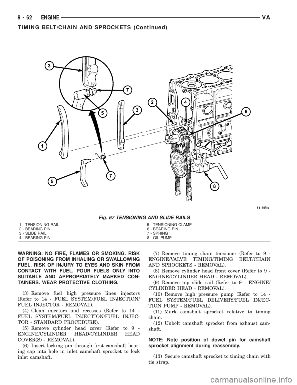
(5) Pull the tensioning rail off of the bearing pins
(Fig. 67).
(6) Release the spring at the slide rail and take it
off of the tensioning arm (Fig. 67).
REMOVAL - INTERMEDIATE GEAR
(1) Disconnect negative battery cable.
(2) Remove engine cover (Refer to 9 - ENGINE -
REMOVAL).
Fig. 66 TIMING CHAIN COVER SEALING SURFACE
1 - TIMING CHAIN COVER
2 - SEALANT BEAD
VAENGINE 9 - 61
TIMING CHAIN COVER (Continued)
Page 800 of 1232
WARNING: NO FIRE, FLAMES OR SMOKING. RISK
OF POISONING FROM INHALING OR SWALLOWING
FUEL. RISK OF INJURY TO EYES AND SKIN FROM
CONTACT WITH FUEL. POUR FUELS ONLY INTO
SUITABLE AND APPROPRIATELY MARKED CON-
TAINERS. WEAR PROTECTIVE CLOTHING.
(3) Remove fuel high pressure lines injectors
(Refer to 14 - FUEL SYSTEM/FUEL INJECTION/
FUEL INJECTOR - REMOVAL).
(4) Clean injectors and recesses (Refer to 14 -
FUEL SYSTEM/FUEL INJECTION/FUEL INJEC-
TOR - STANDARD PROCEDURE).
(5) Remove cylinder head cover (Refer to 9 -
ENGINE/CYLINDER HEAD/CYLINDER HEAD
COVER(S) - REMOVAL).
(6) Insert locking pin through first camshaft bear-
ing cap into hole in inlet camshaft sprocket to lock
inlet camshaft.(7) Remove timing chain tensioner (Refer to 9 -
ENGINE/VALVE TIMING/TIMING BELT/CHAIN
AND SPROCKETS - REMOVAL).
(8) Remove cylinder head front cover (Refer to 9 -
ENGINE/CYLINDER HEAD - REMOVAL).
(9) Remove top slide rail (Refer to 9 - ENGINE/
CYLINDER HEAD - REMOVAL).
(10) Remove high pressure pump (Refer to 14 -
FUEL SYSTEM/FUEL DELIVERY/FUEL INJEC-
TION PUMP - REMOVAL).
(11) Mark camshaft sprocket relative to timing
chain.
(12) Unbolt camshaft sprocket from exhaust cam-
shaft.
NOTE: Note position of dowel pin for camshaft
sprocket alignment during reassembly.
(13) Secure camshaft sprocket to timing chain with
tie strap.
Fig. 67 TENSIONING AND SLIDE RAILS
1 - TENSIONING RAIL 5 - TENSIONING CLAMP
2 - BEARING PIN 6 - BEARING PIN
3 - SLIDE RAIL 7 - SPRING
4 - BEARING PIN 8 - OIL PUMP
9 - 62 ENGINEVA
TIMING BELT/CHAIN AND SPROCKETS (Continued)
Page 804 of 1232
CAUTION: IT IS ESSENTIAL that the installation pro-
cedure for the timing chain is followed exactly. Fail-
ure to do so will result in severe engine damage.
INSTALLATION
INSTALLATION - TENSIONING AND SLIDE RAIL
NOTE: Carefully clean all mating surfaces with
appropriate solvents to assure that no grease or oil
is present during reassembly.
CAUTION: ENSURE THAT THE SPRING IS COR-
RECTLY INSTALLED ON THE TENSIONING CLAMP
AND SLIDE RAIL.
(1) Install rail on bearing pin (Fig. 67).
(2) Install timing cover (Refer to 9 - ENGINE/
VALVE TIMING/TIMING BELT / CHAIN COVER(S)
- INSTALLATION).
(3) Install oil pan bolts. Tighten M6 bolts to 9N´m
(80 lbs.in.) and M8 bolts to 20N´m (15 lbs. ft.).
(4) Install cylinder head (Refer to 9 - ENGINE/
CYLINDER HEAD - INSTALLATION).
(5) Install the engine.
(6) Reconnect negative battery cable.
WARNING: USE EXTREME CAUTION WHEN THE
ENGINE IS OPERATING. DO NOT STAND IN A
DIRECT LINE WITH THE FAN. DO NOT PUT YOUR
HANDS NEAR THE PULLEYS, BELTS OR FAN. DO
NOT WEAR LOOSE CLOTHES.
(7) Start the engine and inspect for leaks. care
must be take to observe the fuel system warning
(Refer to 14 - FUEL SYSTEM - WARNING).
INSTALLATION - INTERMEDIATE GEAR
NOTE: Refer to appropriate injector servicing proce-
dures for cleaning of injectors and recesses.
(1) Install intermediate gear and bushing. Tighten
bolt to 40N´m (30 lbs.ft.)
(2) Install camshaft sprocket, noting dowel pin
alignment. Tighten bolt to 18 N´m (159 lbs. in.).
(3) Remove tie strap retaining timing chain to
sprocket.
WARNING: NO FIRE, FLAMES OR SMOKING. SER-
VICE VEHICLE IN WELL VENTILATED AREA. RISK
OF INJURY FROM INHALING OR SWALLOWING
FUEL. RISK OF INJURY TO EYES AND SKIN FROM
CONTACT WITH FUEL. WEAR PROTECTIVE CLOTH-
ING.(4) Install high pressure pump (Refer to 14 -
FUEL SYSTEM/FUEL DELIVERY/FUEL INJEC-
TION PUMP - INSTALLATION).
(5) Install top slide rail (Refer to 9 - ENGINE/
VALVE TIMING/TIMING BELT/CHAIN AND
SPROCKETS - INSTALLATION).
(6) Install cylinder head front cover (Refer to 9 -
ENGINE/CYLINDER HEAD - INSTALLATION).
(7) Install timing chain tensioner with new gasket
(Refer to 9 - ENGINE/VALVE TIMING/TIMING
BELT/CHAIN AND SPROCKETS - INSTALLA-
TION).
NOTE: Inspect basic position of camshaft and reset
if necessary.
(8) Remove camshaft locking pin.
(9) Install cylinder head cover (Refer to 9 -
ENGINE/CYLINDER HEAD/CYLINDER HEAD
COVER(S) - INSTALLATION).
WARNING: NO FIRE, FLAMES OR SMOKING. SER-
VICE VEHICLE IN WELL VENTILATED AREA. RISK
OF INJURY FROM INHALING OR SWALLOWING
FUEL. RISK OF INJURY TO EYES AND SKIN FROM
CONTACT WITH FUEL. WEAR PROTECTIVE CLOTH-
ING.
(10) Install fuel high pressure lines and injectors
(Refer to 14 - FUEL SYSTEM/FUEL INJECTION/
FUEL INJECTOR - INSTALLATION).
(11) Install engine cover (Refer to 9 - ENGINE -
INSTALLATION).
(12) Connect negative battery cable.
WARNING: USE EXTREME CAUTION WHEN THE
ENGINE IS OPERATING. DO NOT STAND IN A
DIRECT LINE WITH FAN. DO NOT PUT YOUR
HANDS NEAR THE PULLEYS, BELTS OR FAN. DO
NOT WEAR LOOSE CLOTHING.
(13) Start engine and inspect for leaks. Care must
be taken to observe the fuel system warning (Refer to
14 - FUEL SYSTEM - WARNING).
INSTALLATION - TIMING CHAIN TENSIONING
RAIL
NOTE: Carefully clean all mating surfaces with
appropriate solvents to assure that no grease or oil
is present during reassembly.
(1) Install tensioning rail on bearing pin
(2) Install timing cover (Refer to 9 - ENGINE/
VALVE TIMING/TIMING BELT / CHAIN COVER(S)
- INSTALLATION).
9 - 66 ENGINEVA
TIMING BELT/CHAIN AND SPROCKETS (Continued)
Page 805 of 1232
(3) Install oil pan and bolts. Tighten M6 bolts to
9N´m (80 lbs.in.) and M8 bolts to 20N´m (15 lbs. ft.).
(4) Install cylinder head (Refer to 9 - ENGINE/
CYLINDER HEAD - INSTALLATION).
(5) Reconnect negative battery cable.
WARNING: USE EXTREME CAUTION WHEN THE
ENGINE IS OPERATING. DO NOT PUT YOUR
HANDS NEAR THE PULLEYS, BELTS OR FAN. DO
NOT WEAR LOOSE CLOTHES.
(6) Start the engine and inspect for leaks. Care
must be taken to observe the fuel system warning
(Refer to 14 - FUEL SYSTEM - WARNING).
ADJUSTMENTS
INSTALLATION - TIMING CHAIN
CAUTION: IT IS ESSENTIAL that the installation pro-
cedure is followed exactly. Failure to do so will
result in severe engine damage.CAUTION: Cover timing case recesses to prevent
foreign material from entering engine.
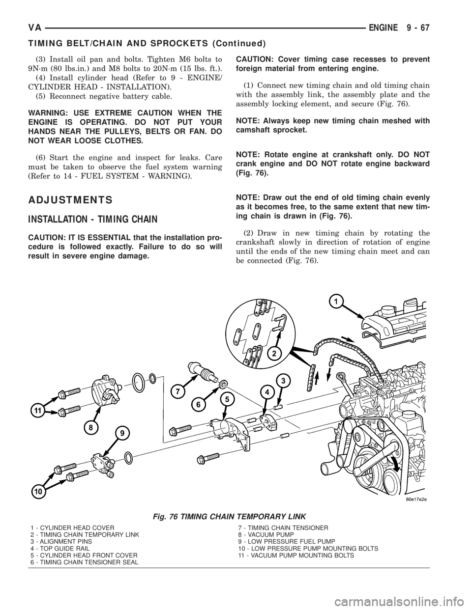
(1) Connect new timing chain and old timing chain
with the assembly link, the assembly plate and the
assembly locking element, and secure (Fig. 76).
NOTE: Always keep new timing chain meshed with
camshaft sprocket.
NOTE: Rotate engine at crankshaft only. DO NOT
crank engine and DO NOT rotate engine backward
(Fig. 76).
NOTE: Draw out the end of old timing chain evenly
as it becomes free, to the same extent that new tim-
ing chain is drawn in (Fig. 76).
(2) Draw in new timing chain by rotating the
crankshaft slowly in direction of rotation of engine
until the ends of the new timing chain meet and can
be connected (Fig. 76).
Fig. 76 TIMING CHAIN TEMPORARY LINK
1 - CYLINDER HEAD COVER
2 - TIMING CHAIN TEMPORARY LINK
3 - ALIGNMENT PINS
4 - TOP GUIDE RAIL
5 - CYLINDER HEAD FRONT COVER
6 - TIMING CHAIN TENSIONER SEAL7 - TIMING CHAIN TENSIONER
8 - VACUUM PUMP
9 - LOW PRESSURE FUEL PUMP
10 - LOW PRESSURE PUMP MOUNTING BOLTS
11 - VACUUM PUMP MOUNTING BOLTS
VAENGINE 9 - 67
TIMING BELT/CHAIN AND SPROCKETS (Continued)