2005 MERCEDES-BENZ SPRINTER warning
[x] Cancel search: warningPage 776 of 1232
(2) Install the rear main seal/adaptor to crankcase
bolts and tighten to 9´Nm (80 lbs.in) (Fig. 29).
(3) Tighten the M6 oil pan bolts to 9N´m (80 lbs
in) and the M8 bolts to 20 N´m (15 lbs ft).
(4) Install the fly wheel and tighten bolts in two
stages (Fig. 29). 45N´m (33 lbs. ft.) then 90É.
(5) Install the oil pan drain plug and tighten to
25N´m (18 lbs ft).
(6) Lower the vehicle.
(7) Fill the crankcase with the correct engine oil,
to the proper level. Refer to owners manual for spec-
ifications.
(8) Connect the negative battery cable.
WARNING: USE EXTREME CAUTION WHEN THE
ENGINE IS OPERATING. DO NOT PUT YOUR
HANDS NEAR THE PULLEYS, BELTS OR FAN. DO
NOT WEAR LOOSE CLOTHES.
(9) Start the engine and inspect for leaks.
CRANKSHAFT OIL SEAL -
FRONT
REMOVAL
(1) Disconnect the negative battery cable.
(2) Remove the accessory drive belt.
(3) Install the retaining lock for the crankshaft/
ring gear.
NOTE: If the hub of the belt pulley/vibration damper
is tight, use a puller to remove it. Do Not tilt the
puller. The groves of the puller MUST mesh fully
into the slots of the belt pulley.
NOTE: Inspect the running surface of the belt pulley
for wear.
(4) Remove the belt pully/vibration damper.
CAUTION: Care must be taken to prevent severe
damage to the crankshaft and mounting whole for
the front crankshaft seal.
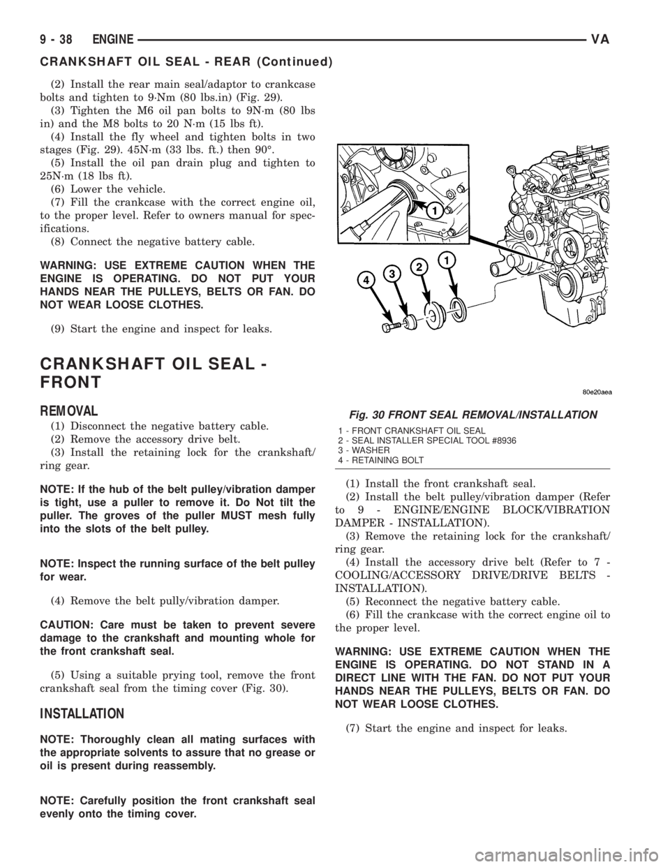
(5) Using a suitable prying tool, remove the front
crankshaft seal from the timing cover (Fig. 30).
INSTALLATION
NOTE: Thoroughly clean all mating surfaces with
the appropriate solvents to assure that no grease or
oil is present during reassembly.
NOTE: Carefully position the front crankshaft seal
evenly onto the timing cover.(1) Install the front crankshaft seal.
(2) Install the belt pulley/vibration damper (Refer
to 9 - ENGINE/ENGINE BLOCK/VIBRATION
DAMPER - INSTALLATION).
(3) Remove the retaining lock for the crankshaft/
ring gear.
(4) Install the accessory drive belt (Refer to 7 -
COOLING/ACCESSORY DRIVE/DRIVE BELTS -
INSTALLATION).
(5) Reconnect the negative battery cable.
(6) Fill the crankcase with the correct engine oil to
the proper level.
WARNING: USE EXTREME CAUTION WHEN THE
ENGINE IS OPERATING. DO NOT STAND IN A
DIRECT LINE WITH THE FAN. DO NOT PUT YOUR
HANDS NEAR THE PULLEYS, BELTS OR FAN. DO
NOT WEAR LOOSE CLOTHES.
(7) Start the engine and inspect for leaks.
Fig. 30 FRONT SEAL REMOVAL/INSTALLATION
1 - FRONT CRANKSHAFT OIL SEAL
2 - SEAL INSTALLER SPECIAL TOOL #8936
3 - WASHER
4 - RETAINING BOLT
9 - 38 ENGINEVA
CRANKSHAFT OIL SEAL - REAR (Continued)
Page 777 of 1232
FLYWHEEL
REMOVAL
(1) Remove transmission (Refer to 21 - TRANS-
MISSION/TRANSAXLE/AUTOMATIC - W5J400 -
REMOVAL).
NOTE: M6x90 bolts must be used with retaining
lock to prevent damage to rear end cover.
(2) Install retaining lock for crankshaft/starter
ring gear.
NOTE: Flywheel does not need balancing or should
it be interchanged.
(3) Remove flywheel with both inner and outer
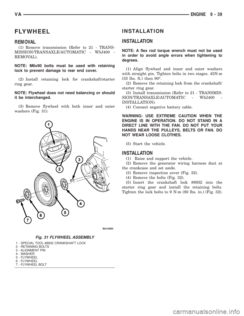
washers (Fig. 31).
INSTALLATION
INSTALLATION
NOTE: A flex rod torque wrench must not be used
in order to avoid angle errors when tightening to
degrees.
(1) Align flywheel and inner and outer washers
with straight pin. Tighten bolts in two stages. 45N´m
(33 lbs. ft.) then 90É.
(2) Remove the retaining lock from the crankshaft/
starter ring gear.
(3) Install transmission (Refer to 21 - TRANSMIS-
SION/TRANSAXLE/AUTOMATIC - W5J400 -
INSTALLATION).
(4) Connect negative battery cable.
WARNING: USE EXTREME CAUTION WHEN THE
ENGINE IS IN OPERATION. DO NOT STAND IN A
DIRECT LINE WITH THE FAN. DO NOT PUT YOUR
HANDS NEAR THE PULLEYS, BELTS OR FAN. DO
NOT WEAR LOOSE CLOTHES.
(5) Start the vehicle.
INSTALLATION
(1) Raise and support the vehicle.
(2) Remove the generator wiring harness duct at
the crankcase and set aside.
(3) Remove inspection cover (Fig. 32).
(4) Remove the bolts (Fig. 32).
(5) Insert the crankshaft lock #8932 into the
starter ring gear and install the retaining bolts.
Tighten the lock bolts to 9 N´m (80 lbs. in.) (Fig. 32).
Fig. 31 FLYWHEEL ASSEMBLY
1 - SPECIAL TOOL #8932 CRANKSHAFT LOCK
2 - RETAINING BOLTS
3 - ALIGNMENT PIN
4 - WASHER
5 - FLYWHEEL
6 - FLYWHEEL
7 - FLYWHEEL BOLT
VAENGINE 9 - 39
Page 782 of 1232
CAUTION: Assemble the piston and connecting rod
so that the arrow is pointing in the direction of
travel (in the opposite direction of power flow). The
marking on the connecting rod is pointing toward
the inlet side.
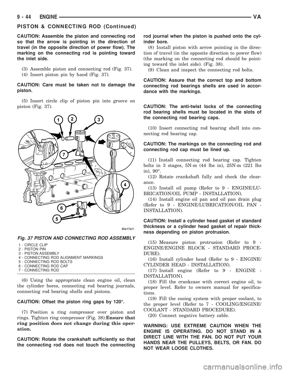
(3) Assemble piston and connecting rod (Fig. 37).
(4) Insert piston pin by hand (Fig. 37).
CAUTION: Care must be taken not to damage the
piston.
(5) Insert circle clip of piston pin into groove on
piston (Fig. 37).
(6) Using the appropriate clean engine oil, clean
the cylinder bores, connecting rod bearing journals,
connecting rod bearing shells and pistons.
CAUTION: Offset the piston ring gaps by 120É.
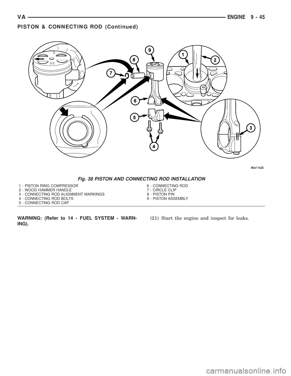
(7) Position a ring compressor over piston and
rings. Tighten ring compressor (Fig. 38).Ensure that
ring position does not change during this oper-
ation.
CAUTION: Rotate the crankshaft sufficiently so that
the connecting rod does not touch the connectingrod journal when the piston is pushed onto the cyl-
inder bore.
(8) Install piston with arrow pointing in the direc-
tion of travel (in the opposite direction to power flow)
(the marking on the connecting rod should be point-
ing toward the inlet side). (Fig. 38).
(9) Clean and inspect the connecting rod bolts.
CAUTION: Assure that the correct top and bottom
connecting rod bearings shells are used in accor-
dance with the markings.
CAUTION: The anti-twist locks of the connecting
rod bearing shells must be located in the slots of
the connecting rod bearing caps.
(10) Insert connecting rod bearing shell into con-
necting rod bearing cap.
CAUTION: The markings on the connecting rod and
connecting rod cap must be lined up.
(11) Install connecting rod bearing cap. Tighten
bolts in 3 stages, 5N´m (44 lbs in), 25N´m (221 lbs
in), 90É.
(12) Rotate crankshaft fully and check the clear-
ance.
(13) Install oil pump (Refer to 9 - ENGINE/LU-
BRICATION/OIL PUMP - INSTALLATION).
(14) Install engine oil pan and oil pan drain plug
(Refer to 9 - ENGINE/LUBRICATION/OIL PAN -
INSTALLATION).
CAUTION: Install a cylinder head gasket of standard
thickness or a cylinder head gasket of repair thick-
ness depending on piston protrusion.
(15) Measure piston protrusion (Refer to 9 -
ENGINE/ENGINE BLOCK - STANDARD PROCE-
DURE).
(16) Install cylinder head (Refer to 9 - ENGINE/
CYLINDER HEAD - INSTALLATION).
(17) Install engine (Refer to 9 - ENGINE -
INSTALLATION).
(18) Fill the crankcase with correct engine oil, to
proper level. Refer to owners manual for specifica-
tions.
(19) Fill the cooing system with proper coolant, to
the proper level (Refer to 7 - COOLING/ENGINE/
COOLANT - STANDARD PROCEDURE).
(20) Connect negative battery cable.
WARNING: USE EXTREME CAUTION WHEN THE
ENGINE IS OPERATING. DO NOT STAND IN A
DIRECT LINE WITH THE FAN. DO NOT PUT YOUR
HANDS NEAR THE PULLEYS, BELTS, OR FAN. DO
NOT WEAR LOOSE CLOTHES.
Fig. 37 PISTON AND CONNECTING ROD ASSEMBLY
1 - CIRCLE CLIP
2 - PISTON PIN
3 - PISTON ASSEMBLY
4 - CONNECTING ROD ALIGNMENT MARKINGS
5 - CONNECTING ROD BOLTS
6 - CONNECTING ROD CAP
7 - CONNECTING ROD
9 - 44 ENGINEVA
PISTON & CONNECTING ROD (Continued)
Page 783 of 1232
WARNING: (Refer to 14 - FUEL SYSTEM - WARN-
ING).(21) Start the engine and inspect for leaks.
Fig. 38 PISTON AND CONNECTING ROD INSTALLATION
1 - PISTON RING COMPRESSOR
2 - WOOD HAMMER HANDLE
3 - CONNECTING ROD ALIGNMENT MARKINGS
4 - CONNECTING ROD BOLTS
5 - CONNECTING ROD CAP6 - CONNECTING ROD
7 - CIRCLE CLIP
8 - PISTON PIN
9 - PISTON ASSEMBLY
VAENGINE 9 - 45
PISTON & CONNECTING ROD (Continued)
Page 786 of 1232
NOTE: If grooves can be felt in the belt pulley/vibra-
tion damper during inspection, the pulley/damper
must be replaced.
(6) Inspect hub at belt pulley/vibration damper for
wear grooves.
(7) Replace front crankshaft seal.
INSTALLATION
NOTE: Align parallel key, fix in place with grease.
Turn to ensure the slot is aligned with parallel key
in crankshaft.
NOTE: Front crankshaft seal must be replaced
before installing the belt pulley/vibration damper.
(1) Position the belt pulley/vibration damper.
(2) Install crankshaft center bolt and washer.
Tighten bolt in two stages. M8.8 bolt to 200N´m (148
lbs. ft.) then 90É, M10.9 bolt to 325N´m (240 lbs. ft.)
then 90É.
(3) Remove the retaining lock for the crankshaft/
ring gear (Fig. 43).
NOTE: Inspect accessory drive belt for wear.
Replace as necessary.
(4) Install accessory drive belt (Refer to 7 - COOL-
ING/ACCESSORY DRIVE/DRIVE BELTS - INSTAL-
LATION).
(5) Reconnect negative battery cable.
WARNING: USE EXTREME CAUTION WHEN THE
ENGINE IS IN OPERATION. DO NOT STAND IN A
DIRECT LINE WITH THE FAN. DO NOT PUT YOUR
HANDS NEAR THE PULLEYS, BELTS OR FAN. DO
NOT WEAR LOOSE CLOTHING.
(6) Start vehicle and inspect for leaks.
VACUUM PUMP
DESCRIPTION
The vacuum pump is operated by a slotted exten-
sion attached to the vacuum pump shaft. The vac-
uum pump shaft slotted extension fits into, and is
driven by, the exhaust camshaft gear.
The vacuum pump is a constant displacement,
vane-type pump. Vacuum is generated by vanes
mounted in the pump rotor. The rotor is located in
the pump housing and is pressed onto the pump
shaft.
The vacuum pump rotating components are inter-
nally lubricated.The vacuum pump is not serviceable and must be
replaced as a unit. Do not disassemble or attempt to
repair the pump.
OPERATION
Vacuum pump output is transmitted to the Heater,
Electronic, Vacuum, Air Conditioner (HEVAC) and
speed control, systems through a supply hose. The
hose is connected to an outlet port on the pump hous-
ing and uses an in-line check valve to retain system
vacuum when vehicle is not running.
Pump output ranges from a minimum of 8.5 to 25
inches vacuum.
The pump rotor and vanes are rotated by the pump
drive gear. The drive gear is operated by the exhaust
camshaft gear.
REMOVAL
(1) Disconnect negative battery cable.
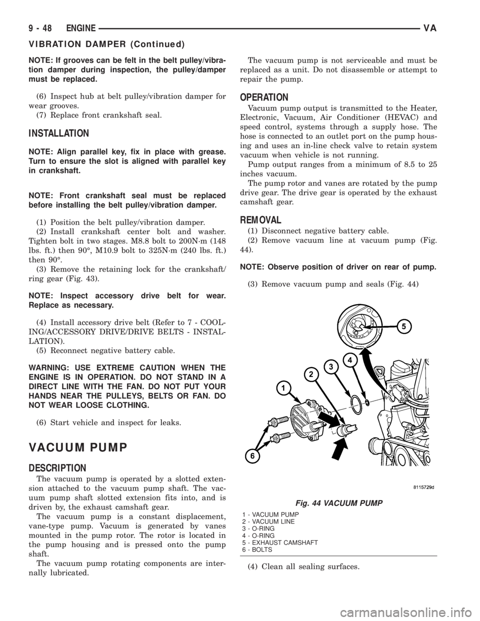
(2) Remove vacuum line at vacuum pump (Fig.
44).
NOTE: Observe position of driver on rear of pump.
(3) Remove vacuum pump and seals (Fig. 44)
(4) Clean all sealing surfaces.
Fig. 44 VACUUM PUMP
1 - VACUUM PUMP
2 - VACUUM LINE
3 - O-RING
4 - O-RING
5 - EXHAUST CAMSHAFT
6 - BOLTS
9 - 48 ENGINEVA
VIBRATION DAMPER (Continued)
Page 787 of 1232
INSTALLATION
(1) Clean all sealing surfaces.
(2) Position driver on rear of pump and install vac-
uum pump with new seals. Tighten bolts to 14N´m
(124 lbs. in.). (Fig. 44)
(3) Install vacuum line to vacuum pump (Fig. 44).
(4) Connect negative battery cable.
WARNING: USE EXTREME CAUTION WHEN THE
ENGINE IS OPERATING. DO NOT STAND IN A
DIRECT LINE WITH THE FAN. DO NOT PUT YOUR
HANDS NEAR THE PULLEYS, BELTS OR FAN. DO
NOT WEAR LOOSE CLOTHES.
(5) Start the engine and inspect for leaks.
LEFT MOUNT
REMOVAL
(1) Install engine support fixture #8534 with adap-
tors #8534±16 and raise the engine slightly.
(2) Raise and support the vehicle.
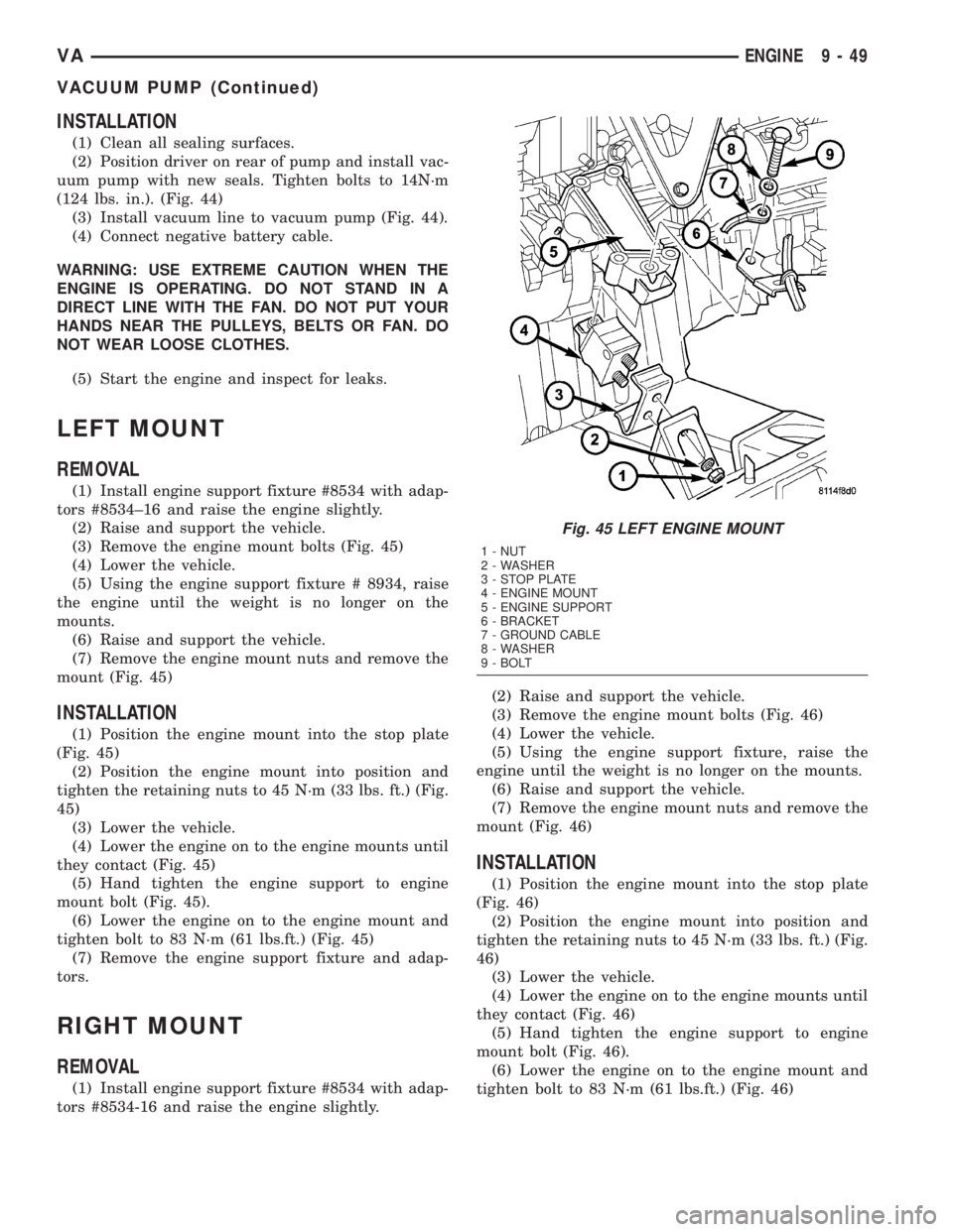
(3) Remove the engine mount bolts (Fig. 45)
(4) Lower the vehicle.
(5) Using the engine support fixture # 8934, raise
the engine until the weight is no longer on the
mounts.
(6) Raise and support the vehicle.
(7) Remove the engine mount nuts and remove the
mount (Fig. 45)
INSTALLATION
(1) Position the engine mount into the stop plate
(Fig. 45)
(2) Position the engine mount into position and
tighten the retaining nuts to 45 N´m (33 lbs. ft.) (Fig.
45)
(3) Lower the vehicle.
(4) Lower the engine on to the engine mounts until
they contact (Fig. 45)
(5) Hand tighten the engine support to engine
mount bolt (Fig. 45).
(6) Lower the engine on to the engine mount and
tighten bolt to 83 N´m (61 lbs.ft.) (Fig. 45)
(7) Remove the engine support fixture and adap-
tors.
RIGHT MOUNT
REMOVAL
(1) Install engine support fixture #8534 with adap-
tors #8534-16 and raise the engine slightly.(2) Raise and support the vehicle.
(3) Remove the engine mount bolts (Fig. 46)
(4) Lower the vehicle.
(5) Using the engine support fixture, raise the
engine until the weight is no longer on the mounts.
(6) Raise and support the vehicle.
(7) Remove the engine mount nuts and remove the
mount (Fig. 46)
INSTALLATION
(1) Position the engine mount into the stop plate
(Fig. 46)
(2) Position the engine mount into position and
tighten the retaining nuts to 45 N´m (33 lbs. ft.) (Fig.
46)
(3) Lower the vehicle.
(4) Lower the engine on to the engine mounts until
they contact (Fig. 46)
(5) Hand tighten the engine support to engine
mount bolt (Fig. 46).
(6) Lower the engine on to the engine mount and
tighten bolt to 83 N´m (61 lbs.ft.) (Fig. 46)
Fig. 45 LEFT ENGINE MOUNT
1 - NUT
2 - WASHER
3 - STOP PLATE
4 - ENGINE MOUNT
5 - ENGINE SUPPORT
6 - BRACKET
7 - GROUND CABLE
8 - WASHER
9 - BOLT
VAENGINE 9 - 49
VACUUM PUMP (Continued)
Page 788 of 1232
(7) Remove the engine support fixture and adap-
tors.
OIL
REMOVAL - OIL SEPARATOR
(1) Disconnect breather hose.
(2) Remove the separator retaining bolts
(3) Twist to remove oil separator from cover.
INSTALLATION - OIL SEPARATOR
(1) Lubricate the oil separator o - ring with clean
engine oil.
(2) Position separator above cover and apply down-
ward pressure to seat.
(3) Install retaining bolts and tighten to 8N´m (70
lbs. in.).
(4) Connect breather hose.
OIL COOLER & LINES
REMOVAL
WARNING: RISK OF INJURY TO SKIN AND EYES
DUE TO SCALDING FROM HOT COOLANT. DO NOTOPEN THE COOLING SYSTEM UNLESS THE TEM-
PERATURE IS BELOW 194ÉF (90ÉC). WEAR PRO-
TECTIVE CLOTHING AND EYE WEAR. RISK OF
POISONING IF COOLANT IS SWALLOWED. STORE
COOLANT IN PROPER AND APPROPRIATELY
MARKED CONTAINERS.
(1) Drain cooling system.
(2) Remove the oil filter.
(3) Remove the coolant hoses from the oil cooler
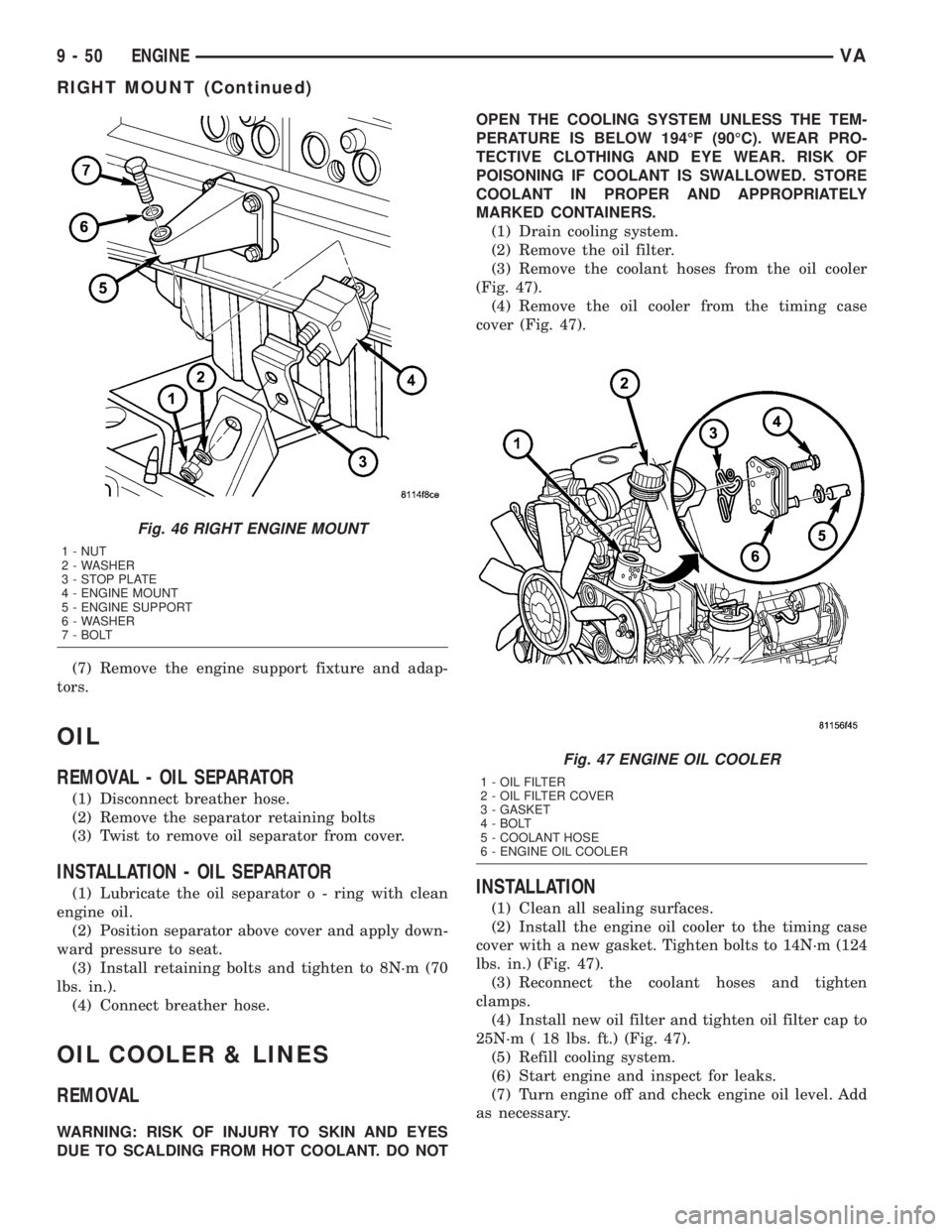
(Fig. 47).
(4) Remove the oil cooler from the timing case
cover (Fig. 47).
INSTALLATION
(1) Clean all sealing surfaces.
(2) Install the engine oil cooler to the timing case
cover with a new gasket. Tighten bolts to 14N´m (124
lbs. in.) (Fig. 47).
(3) Reconnect the coolant hoses and tighten
clamps.
(4) Install new oil filter and tighten oil filter cap to
25N´m ( 18 lbs. ft.) (Fig. 47).
(5) Refill cooling system.
(6) Start engine and inspect for leaks.
(7) Turn engine off and check engine oil level. Add
as necessary.
Fig. 46 RIGHT ENGINE MOUNT
1 - NUT
2 - WASHER
3 - STOP PLATE
4 - ENGINE MOUNT
5 - ENGINE SUPPORT
6 - WASHER
7 - BOLT
Fig. 47 ENGINE OIL COOLER
1 - OIL FILTER
2 - OIL FILTER COVER
3 - GASKET
4 - BOLT
5 - COOLANT HOSE
6 - ENGINE OIL COOLER
9 - 50 ENGINEVA
RIGHT MOUNT (Continued)
Page 791 of 1232
(3) Tighten the bolt of the transmission bell hous-
ing to oil pan to 40N´m (30 lbs. ft.).(4) Install the wiring harness duct (Fig. 51).
(5) Install the transmission lines (Fig. 51).
(6) Connect the oil level sensor (Fig. 51).
(7) Lower the vehicle.
(8) Lower the engine until the engine mount and
engine supports make contact.
(9) Start and hand tighten the engine mount bolts.
(10) Lower the engine the rest of the way and
remove the engine support fixture.
(11) Tighten the engine mount bolts to 83 N´m (61
lbs. ft.).
(12) Install the sway bar and tighten bolts to 30
N´m (22 lbs. ft.).
(13) Refill crankcase with the proper engine oil to
the proper level. Refer to owners manual for specifi-
cation.
(14) Reconnect negative battery cable.
WARNING: USE EXTREME CAUTION WHEN THE
ENGINE IS OPERATING. DO NOT PUT YOUR
HANDS NEAR THE PULLEYS, BELTS OR FAN. DO
NOT WEAR LOOSE CLOTHES.
(15) Start the engine and inspect for leaks.
OIL PUMP
REMOVAL
REMOVAL
(1) Remove the oil pan (Refer to 9 - ENGINE/LU-
BRICATION/OIL PAN - REMOVAL).
(2) Remove the oil pump bolts (Fig. 51).
(3) Press the chain tensioner off of the oil pump
chain, and remove pump from chain.
(4) Remove the oil pump, pick-up tube and O-ring
(Fig. 51).
REMOVAL- OIL PUMP CHAIN
(1) Disconnect negative battery cable.
(2) Remove oil pan (Refer to 9 - ENGINE/LUBRI-
CATION/OIL PAN - REMOVAL).
(3) Remove oil pump (Refer to 9 - ENGINE/LU-
BRICATION/OIL PUMP - REMOVAL).
NOTE: Make sure the pin of the thrust spindle is
backed out into the thrust spindle before seating
the thrust spindle to the oil pump chain.
(4) Using special tool #8948 and thrust pin #9311,
position and fit chain seperating tool and thrust spin-
dle onto a link of the oil pump chain (Fig. 54).
(5) Screw the thrust pin in and seperate the oil
pump chain link.
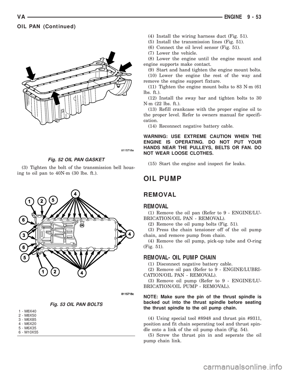
Fig. 52 OIL PAN GASKET
Fig. 53 OIL PAN BOLTS
1 - M8X40
2 - M8X50
3 - M6X85
4 - M6X20
5 - M6X35
6 - M10X55
VAENGINE 9 - 53
OIL PAN (Continued)