2005 MERCEDES-BENZ SPRINTER warning
[x] Cancel search: warningPage 272 of 1232
(8) Remove the seat belt turning loop height
adjuster from the inner B-pillar.
INSTALLATION
WARNING: ON VEHICLES EQUIPPED WITH AIR-
BAGS, DISABLE THE SUPPLEMENTAL RESTRAINT
SYSTEM BEFORE ATTEMPTING ANY STEERING
WHEEL, STEERING COLUMN, DRIVER AIRBAG,
PASSENGER AIRBAG, SEAT BELT TENSIONER, OR
INSTRUMENT PANEL COMPONENT DIAGNOSIS OR
SERVICE. DISCONNECT AND ISOLATE THE BAT-
TERY NEGATIVE (GROUND) CABLE, THEN WAIT
TWO MINUTES FOR THE SYSTEM CAPACITOR TO
DISCHARGE BEFORE PERFORMING FURTHER
DIAGNOSIS OR SERVICE. THIS IS THE ONLY SUREWAY TO DISABLE THE SUPPLEMENTAL
RESTRAINT SYSTEM. FAILURE TO TAKE THE
PROPER PRECAUTIONS COULD RESULT IN ACCI-
DENTAL AIRBAG DEPLOYMENT AND POSSIBLE
PERSONAL INJURY.
WARNING: DURING AND FOLLOWING ANY SEAT
BELT SERVICE, CAREFULLY INSPECT ALL SEAT
BELTS, BUCKLES, MOUNTING HARDWARE,
RETRACTORS, AND ANCHORS FOR PROPER
INSTALLATION, OPERATION, OR DAMAGE.
REPLACE ANY BELT THAT IS CUT, FRAYED, OR
TORN. STRAIGHTEN ANY BELT THAT IS TWISTED.
TIGHTEN ANY LOOSE FASTENERS. REPLACE ANY
BELT THAT HAS A DAMAGED OR INOPERATIVE
BUCKLE OR RETRACTOR. REPLACE ANY BELT
THAT HAS A BENT OR DAMAGED LATCH PLATE
OR ANCHOR PLATE. NEVER ATTEMPT TO REPAIR
A SEAT BELT COMPONENT. ALWAYS REPLACE
DAMAGED OR FAULTY SEAT BELT COMPONENTS
WITH THE CORRECT, NEW AND UNUSED
REPLACEMENT PARTS LISTED IN THE
DAIMLERCHRYSLER MOPAR PARTS CATALOG.
(1) Position the seat belt turning loop height
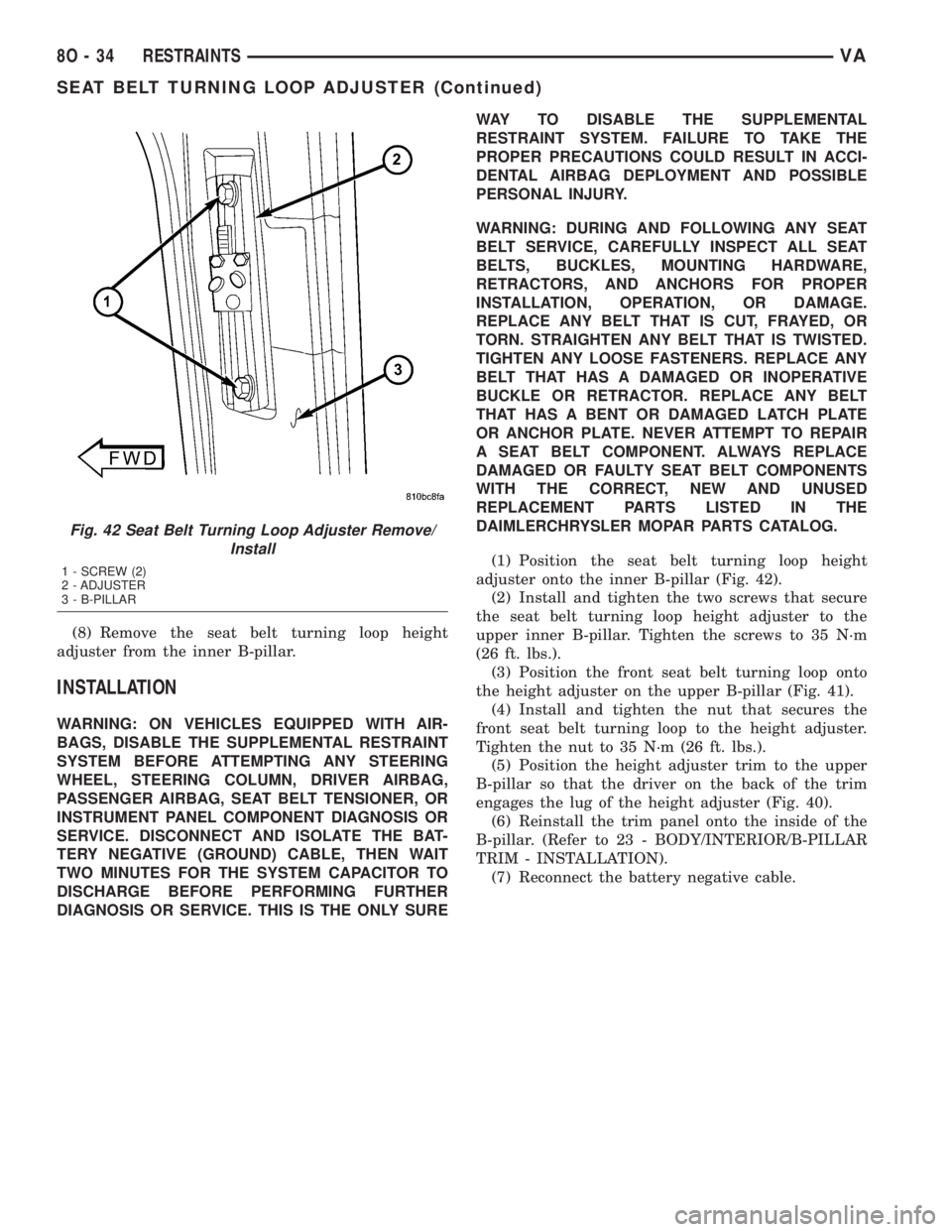
adjuster onto the inner B-pillar (Fig. 42).
(2) Install and tighten the two screws that secure
the seat belt turning loop height adjuster to the
upper inner B-pillar. Tighten the screws to 35 N´m
(26 ft. lbs.).
(3) Position the front seat belt turning loop onto
the height adjuster on the upper B-pillar (Fig. 41).
(4) Install and tighten the nut that secures the
front seat belt turning loop to the height adjuster.
Tighten the nut to 35 N´m (26 ft. lbs.).
(5) Position the height adjuster trim to the upper
B-pillar so that the driver on the back of the trim
engages the lug of the height adjuster (Fig. 40).
(6) Reinstall the trim panel onto the inside of the
B-pillar. (Refer to 23 - BODY/INTERIOR/B-PILLAR
TRIM - INSTALLATION).
(7) Reconnect the battery negative cable.
Fig. 42 Seat Belt Turning Loop Adjuster Remove/
Install
1 - SCREW (2)
2 - ADJUSTER
3 - B-PILLAR
8O - 34 RESTRAINTSVA
SEAT BELT TURNING LOOP ADJUSTER (Continued)
Page 273 of 1232
SPEED CONTROL
TABLE OF CONTENTS
page page
SPEED CONTROL
DESCRIPTION..........................1
OPERATION............................1
SPECIFICATIONS
TORQUE.............................2
CABLE
DESCRIPTION..........................3SERVO
DESCRIPTION..........................3
SWITCH
REMOVAL.............................3
INSTALLATION..........................3
SPEED CONTROL
DESCRIPTION
The speed control system is electronically con-
trolled by the Engine Control Module (ECM).A
cable and a vacuum controlled servo are not
used. This is a servo-less system.Control of the
system is accomplished by a 4-position, instrument
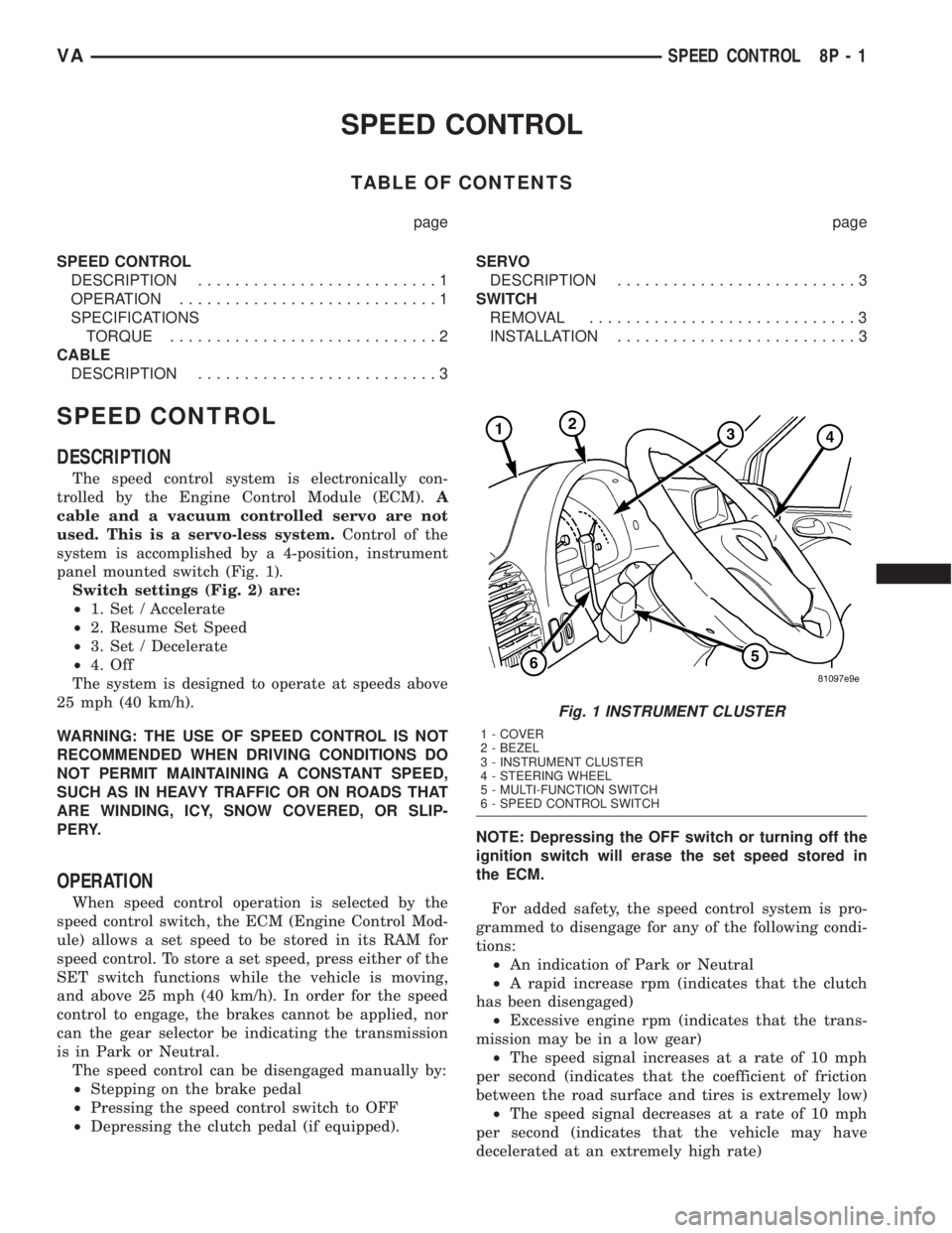
panel mounted switch (Fig. 1).
Switch settings (Fig. 2) are:
²1. Set / Accelerate
²2. Resume Set Speed
²3. Set / Decelerate
²4. Off
The system is designed to operate at speeds above
25 mph (40 km/h).
WARNING: THE USE OF SPEED CONTROL IS NOT
RECOMMENDED WHEN DRIVING CONDITIONS DO
NOT PERMIT MAINTAINING A CONSTANT SPEED,
SUCH AS IN HEAVY TRAFFIC OR ON ROADS THAT
ARE WINDING, ICY, SNOW COVERED, OR SLIP-
PERY.
OPERATION
When speed control operation is selected by the
speed control switch, the ECM (Engine Control Mod-
ule) allows a set speed to be stored in its RAM for
speed control. To store a set speed, press either of the
SET switch functions while the vehicle is moving,
and above 25 mph (40 km/h). In order for the speed
control to engage, the brakes cannot be applied, nor
can the gear selector be indicating the transmission
is in Park or Neutral.
The speed control can be disengaged manually by:
²Stepping on the brake pedal
²Pressing the speed control switch to OFF
²Depressing the clutch pedal (if equipped).NOTE: Depressing the OFF switch or turning off the
ignition switch will erase the set speed stored in
the ECM.
For added safety, the speed control system is pro-
grammed to disengage for any of the following condi-
tions:
²An indication of Park or Neutral
²A rapid increase rpm (indicates that the clutch
has been disengaged)
²Excessive engine rpm (indicates that the trans-
mission may be in a low gear)
²The speed signal increases at a rate of 10 mph
per second (indicates that the coefficient of friction
between the road surface and tires is extremely low)
²The speed signal decreases at a rate of 10 mph
per second (indicates that the vehicle may have
decelerated at an extremely high rate)
Fig. 1 INSTRUMENT CLUSTER
1 - COVER
2 - BEZEL
3 - INSTRUMENT CLUSTER
4 - STEERING WHEEL
5 - MULTI-FUNCTION SWITCH
6 - SPEED CONTROL SWITCH
VASPEED CONTROL 8P - 1
Page 277 of 1232
VEHICLE THEFT SECURITY
TABLE OF CONTENTS
page page
VEHICLE THEFT SECURITY
DESCRIPTION..........................1
OPERATION............................1
DIAGNOSIS AND TESTING - VEHICLE THEFT
SECURITY............................1
INTRUSION SENSOR
REMOVAL.............................2
INSTALLATION..........................2
SECURITY SYSTEM MODULE
REMOVAL.............................2
INSTALLATION..........................2SENTRY KEY REMOTE ENTRY MODULE
DESCRIPTION..........................2
OPERATION............................3
REMOVAL.............................3
INSTALLATION..........................4
SIREN
REMOVAL.............................4
INSTALLATION..........................4
TRANSPONDER KEY
DESCRIPTION..........................5
OPERATION............................5
VEHICLE THEFT SECURITY
DESCRIPTION
An anti-theft alarm with battery powered horn is
available as an option and includes interior monitor-
ing, anti-tow away protection and rear window mon-
itoring based on the heater wires. The alarm is
automatically activated when the central locking sys-
tem is operated.
The alarm will sound when any of the following
occur:
²A door is opened
²A door is unlocked from inside the vehicle
²The hood is opened
²The vehicle is raised at the front or rear
²The trailer wire harness is disconnected
²Movements inside the vehicle
²The central locking is unlocked by a key at any
other door than the driver's door
The alarm is functional about 30 seconds after the
vehicle is locked using the RKE transmitter or the
key in the driver's door. Activation is indicated by the
indicator lights flashing three times and the warning
lamp flashing in the switch. If persons or animals
remain in the locked vehicle, the operator should
switch off the interior monitor to avoid a false alarm.
OPERATION
The anti-theft alarm is activated/deactivated by
locking/unlocking the vehicle with the remote trans-
mitter or with the key at the driver's door. The key
must be held in the locking position for more than
two seconds. Activation is indicated by the turn sig-
nal lights flashing once. Unlocking the vehicle at one
of the other doors will trigger an alarm.The interior monitoring system included in the
anti-theft alarm is based on ultrasonics and triggers
an alarm if an object intrudes the interior of the
vehicle or if any movement is detected inside the
vehicle. For proper and effective protection, all win-
dows and the sunroof must be closed.
To switch off the interior monitoring system and /
or the anti-tow away protection, a switch with LED
indicator light is provided in the switch panel. An
alarm button enables the operator to trigger an
alarm manually and to lock all doors if they are
closed. Triggering an alarm makes the horn sound
and the turn signals flash until the alarm is switched
off.
The anti-theft alarm control unit includes a gradi-
ent indicator as anti-tow away protection. The gradi-
ent indicator triggers an audible and visual alarm if
the vehicle is lifted (to tow away or to remove the
wheels). The alarm remains effective even if the bat-
tery is disconnected as the horn is powered by its
own battery. The interior monitoring system should
be switched off if people and/or animals are left in
the vehicle.
DIAGNOSIS AND TESTING - VEHICLE THEFT
SECURITY
Any diagnosis of the Vehicle Theft Security
system should begin with the use of the DRB
IIItdiagnostic tool. For information on the use
of the DRB IIIt, refer to the appropriate Diag-
nostic Service Manual.
VAVEHICLE THEFT SECURITY 8Q - 1
Page 283 of 1232
WIPERS/WASHERS
TABLE OF CONTENTS
page page
WIPERS/WASHERS
DESCRIPTION..........................1
OPERATION............................3
DIAGNOSIS AND TESTING - WIPER &
WASHER SYSTEM.....................5
CLEANING - WIPER & WASHER SYSTEM.....5
INSPECTION - WIPER & WASHER SYSTEM . . . 6
CHECK VALVE
DESCRIPTION..........................7
OPERATION............................7
REMOVAL.............................7
INSTALLATION..........................7
WASHER FLUID LEVEL SWITCH
DESCRIPTION..........................7
OPERATION............................8
WASHER HOSES/TUBES
DESCRIPTION..........................8
OPERATION............................9
WASHER NOZZLE
DESCRIPTION..........................9
OPERATION............................9
REMOVAL.............................9
INSTALLATION..........................9
WASHER PUMP/MOTOR
DESCRIPTION..........................9
OPERATION...........................10
REMOVAL.............................10
INSTALLATION.........................10
WASHER RESERVOIR
DESCRIPTION.........................11OPERATION...........................11
REMOVAL.............................11
INSTALLATION.........................12
WIPER ARM
DESCRIPTION.........................13
OPERATION...........................14
REMOVAL.............................14
INSTALLATION.........................14
WIPER BLADE
DESCRIPTION.........................15
OPERATION...........................15
REMOVAL.............................16
INSTALLATION.........................16
WIPER LINKAGE
DESCRIPTION.........................17
OPERATION...........................17
REMOVAL.............................17
INSTALLATION.........................18
WIPER MOTOR
DESCRIPTION.........................19
OPERATION...........................19
REMOVAL.............................19
INSTALLATION.........................19
WIPER RELAY
DESCRIPTION.........................20
OPERATION...........................21
REMOVAL.............................22
INSTALLATION.........................22
WIPERS/WASHERS
DESCRIPTION
An electrically operated intermittent wiper and
washer system is standard factory-installed safety
equipment on this model (Fig. 1). The wiper and
washer system includes the following major compo-
nents, which are described in further detail else-
where in this service information:
²Check Valve- The washer system check valve
is integral to the plumbing fitting located in the
washer plumbing between the cowl plenum washer
hose and the two washer nozzle hoses, and is located
beneath the cowl top panel at the base of the wind-
shield in the engine compartment.
²Multi-Function Switch- The multi-function
switch is secured to the top of the steering column,just below the steering wheel. Only the left (lighting),
right (wiper) control stalks and the hazard warning
switch button for the multi-function switch are visi-
ble, the remainder of the switch is concealed beneath
the steering column shrouds. The multi-function
switch contains all of the switches for both the wiper
and washer systems.(Refer to 8 - ELECTRICAL/
LAMPS/LIGHTING - EXTERIOR/MULTI-FUNC-
TION SWITCH - DESCRIPTION)
²Washer Fluid Level Switch- The optional
washer fluid level switch is integral to a unique ver-
sion of the washer pump/motor unit, which is located
in a dedicated hole on the top of the sump area near
the back of the windshield washer reservoir on the
right front fender wheel house in the engine com-
partment.
²Washer Nozzle- A single washer nozzle with
three separate orifices is secured with integral snap
VAWIPERS/WASHERS 8R - 1
Page 287 of 1232
and methods. Proper testing of the intermittent wipe
logic circuitry within the fuse block requires the use
of a DRBIIItscan tool. Refer to the appropriate diag-
nostic information. Refer to the owner's manual in
the vehicle glove box for more information on the fea-
tures and operation of the wiper and washer system.
DIAGNOSIS AND TESTING - WIPER &
WASHER SYSTEM
If the wiper motor operates, but the wipers do not
move on the windshield, replace the faulty wiper
linkage module. If the washer pump/motor operates,
but no washer fluid is dispensed on the glass; or, if
the wipers operate, but chatter, lift, or do not clear
the glass, clean and inspect the wiper and washer
system components as required. (Refer to 8 - ELEC-
TRICAL/WIPERS/WASHERS - CLEANING) and
(Refer to 8 - ELECTRICAL/WIPERS/WASHERS -
INSPECTION). For diagnosis and testing of the
multi-function switch (Refer to 8 - ELECTRICAL/
LAMPS/LIGHTING - EXTERIOR/MULTI-FUNC-
TION SWITCH - DIAGNOSIS AND TESTING).
Refer to the appropriate wiring information. The wir-
ing information includes wiring diagrams, proper
wire and connector repair procedures, details of wire
harness routing and retention, connector pin-out
information and location views for the various wire
harness connectors, splices and grounds.
The hard wired circuits and components of the
wiper and washer system may be diagnosed and
tested using conventional diagnostic tools and proce-
dures. However, conventional diagnostic methods
may not prove conclusive in the diagnosis of the
intermittent wipe logic circuitry contained within the
fuse block underneath the steering column. The most
reliable, efficient, and accurate means to diagnose
the intermittent wipe logic circuitry requires the use
of a DRBIIItscan tool. Refer to the appropriate diag-
nostic information.
WARNING: ON VEHICLES EQUIPPED WITH AIR-
BAGS, DISABLE THE SUPPLEMENTAL RESTRAINT
SYSTEM BEFORE ATTEMPTING ANY STEERING
WHEEL, STEERING COLUMN, DRIVER AIRBAG,
PASSENGER AIRBAG, SEAT BELT TENSIONER, OR
INSTRUMENT PANEL COMPONENT DIAGNOSIS OR
SERVICE. DISCONNECT AND ISOLATE THE BAT-
TERY NEGATIVE (GROUND) CABLE, THEN WAIT
TWO MINUTES FOR THE SYSTEM CAPACITOR TO
DISCHARGE BEFORE PERFORMING FURTHER
DIAGNOSIS OR SERVICE. THIS IS THE ONLY SURE
WAY TO DISABLE THE SUPPLEMENTAL
RESTRAINT SYSTEM. FAILURE TO TAKE THE
PROPER PRECAUTIONS COULD RESULT IN ACCI-
DENTAL AIRBAG DEPLOYMENT AND POSSIBLE
PERSONAL INJURY.
CLEANING - WIPER & WASHER SYSTEM
WIPER SYSTEM
The squeegees of wiper blades exposed to the ele-
ments for a long time tend to lose their wiping effec-
tiveness. Periodic cleaning of the squeegees is
suggested to remove any deposits of salt or road film.
The wiper blades, arms, and windshield glass should
only be cleaned using a sponge or soft cloth and
windshield washer fluid, a mild detergent, or a non-
abrasive cleaner. If the wiper blades continue to
leave streaks, smears, hazing, or beading on the
glass after thorough cleaning of the squeegees and
the glass, the entire wiper blade assembly must be
replaced.
CAUTION: Protect the rubber squeegees of the
wiper blades from any petroleum-based cleaners,
solvents, or contaminants. These products can rap-
idly deteriorate the rubber squeegees.
WASHER SYSTEM
If the washer system is contaminated with foreign
material, drain the washer reservoir by removing the
washer pump/motor from the reservoir. Clean foreign
material from the inside of the washer pump/motor
inlet nipple and the washer reservoir using clean
washer fluid, a mild detergent, or a non-abrasive
cleaner. Flush foreign material from the washer sys-
tem plumbing by first disconnecting the washer
hoses from the washer nozzles, then running the
washer pump/motor to run clean washer fluid or
water through the system. Plugged or restricted
washer nozzles should be carefully back-flushed
using compressed air. If the washer nozzle obstruc-
tion cannot be cleared, replace the washer nozzle.
CAUTION: Never introduce petroleum-based clean-
ers, solvents, or contaminants into the washer sys-
tem. These products can rapidly deteriorate the
rubber seals and hoses of the washer system, as
well as the rubber squeegees of the wiper blades.
CAUTION: Never use compressed air to flush the
washer system plumbing. Compressed air pres-
sures are too great for the washer system plumbing
components and will result in further system dam-
age. Never use sharp instruments to clear a
plugged washer nozzle or damage to the nozzle ori-
fice and improper nozzle spray patterns will result.
VAWIPERS/WASHERS 8R - 5
WIPERS/WASHERS (Continued)
Page 293 of 1232
(3) Using hand pressure, press firmly and evenly
on the washer pump until the inlet nipple is fully
seated in the rubber grommet seal in the washer res-
ervoir mounting hole (Fig. 10).
(4)
If the vehicle is so equipped, reconnect the
washer fluid level switch vent hose to the barbed vent
nipple at the top of the washer pump/motor housing.
(5) Reconnect the washer hose to the barbed outlet
nipple of the washer pump.
(6) Reconnect the vehicle wire harness connector
for the washer pump/motor unit to the motor connec-
tor receptacle.
(7) Refill the washer reservoir with the washer
fluid drained from the reservoir during the removal
procedure.
WASHER RESERVOIR
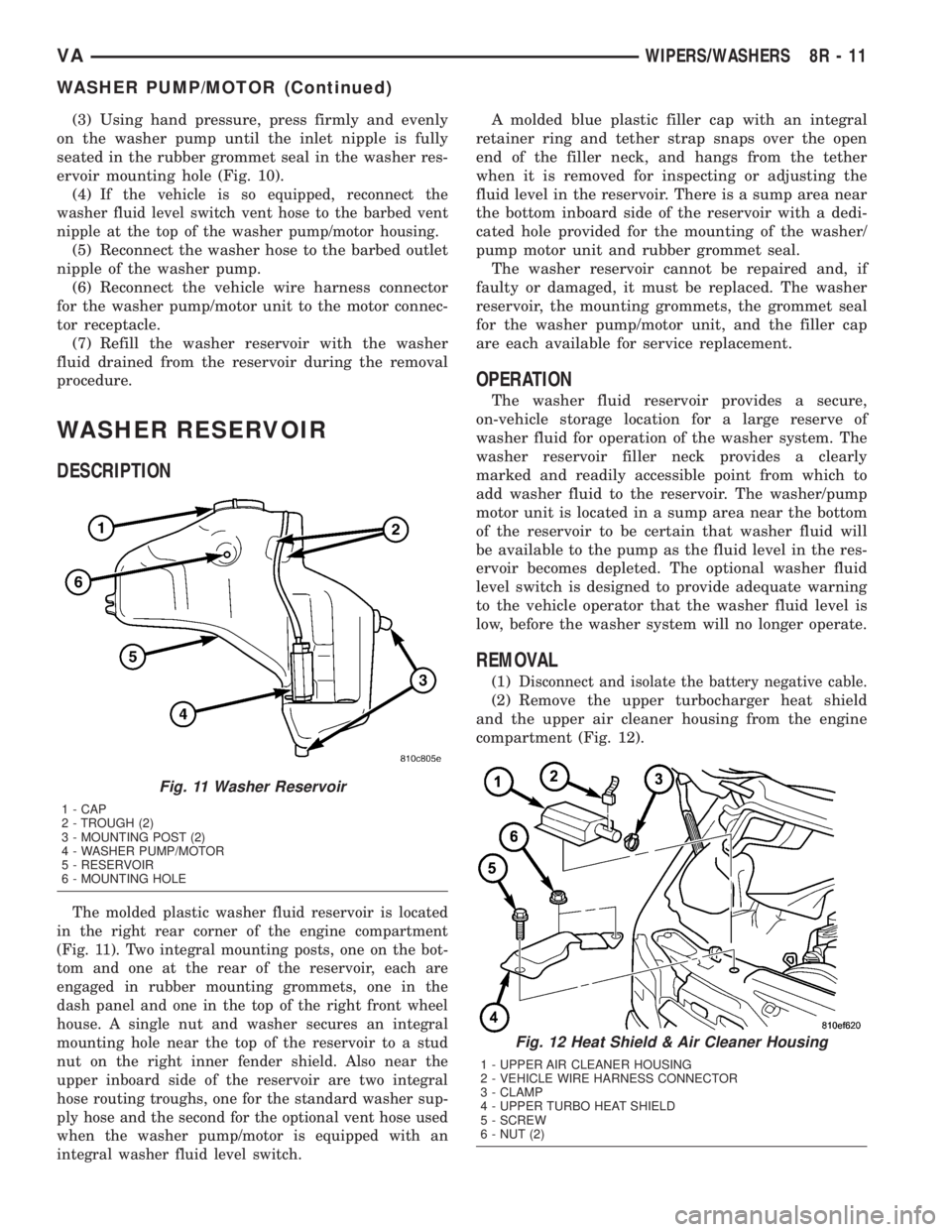
DESCRIPTION
The molded plastic washer fluid reservoir is located
in the right rear corner of the engine compartment
(Fig. 11). Two integral mounting posts, one on the bot-
tom and one at the rear of the reservoir, each are
engaged in rubber mounting grommets, one in the
dash panel and one in the top of the right front wheel
house. A single nut and washer secures an integral
mounting hole near the top of the reservoir to a stud
nut on the right inner fender shield. Also near the
upper inboard side of the reservoir are two integral
hose routing troughs, one for the standard washer sup-
ply hose and the second for the optional vent hose used
when the washer pump/motor is equipped with an
integral washer fluid level switch.
A molded blue plastic filler cap with an integral
retainer ring and tether strap snaps over the open
end of the filler neck, and hangs from the tether
when it is removed for inspecting or adjusting the
fluid level in the reservoir. There is a sump area near
the bottom inboard side of the reservoir with a dedi-
cated hole provided for the mounting of the washer/
pump motor unit and rubber grommet seal.
The washer reservoir cannot be repaired and, if
faulty or damaged, it must be replaced. The washer
reservoir, the mounting grommets, the grommet seal
for the washer pump/motor unit, and the filler cap
are each available for service replacement.
OPERATION
The washer fluid reservoir provides a secure,
on-vehicle storage location for a large reserve of
washer fluid for operation of the washer system. The
washer reservoir filler neck provides a clearly
marked and readily accessible point from which to
add washer fluid to the reservoir. The washer/pump
motor unit is located in a sump area near the bottom
of the reservoir to be certain that washer fluid will
be available to the pump as the fluid level in the res-
ervoir becomes depleted. The optional washer fluid
level switch is designed to provide adequate warning
to the vehicle operator that the washer fluid level is
low, before the washer system will no longer operate.
REMOVAL
(1)Disconnect and isolate the battery negative cable.
(2) Remove the upper turbocharger heat shield
and the upper air cleaner housing from the engine
compartment (Fig. 12).
Fig. 11 Washer Reservoir
1 - CAP
2 - TROUGH (2)
3 - MOUNTING POST (2)
4 - WASHER PUMP/MOTOR
5 - RESERVOIR
6 - MOUNTING HOLE
Fig. 12 Heat Shield & Air Cleaner Housing
1 - UPPER AIR CLEANER HOUSING
2 - VEHICLE WIRE HARNESS CONNECTOR
3 - CLAMP
4 - UPPER TURBO HEAT SHIELD
5 - SCREW
6 - NUT (2)
VAWIPERS/WASHERS 8R - 11
WASHER PUMP/MOTOR (Continued)
Page 304 of 1232
REMOVAL
WARNING: ON VEHICLES EQUIPPED WITH AIR-
BAGS, DISABLE THE SUPPLEMENTAL RESTRAINT
SYSTEM BEFORE ATTEMPTING ANY STEERING
WHEEL, STEERING COLUMN, DRIVER AIRBAG,
PASSENGER AIRBAG, SEAT BELT TENSIONER, OR
INSTRUMENT PANEL COMPONENT DIAGNOSIS OR
SERVICE. DISCONNECT AND ISOLATE THE BAT-
TERY NEGATIVE (GROUND) CABLE, THEN WAIT
TWO MINUTES FOR THE SYSTEM CAPACITOR TO
DISCHARGE BEFORE PERFORMING FURTHER
DIAGNOSIS OR SERVICE. THIS IS THE ONLY SURE
WAY TO DISABLE THE SUPPLEMENTAL
RESTRAINT SYSTEM. FAILURE TO TAKE THE
PROPER PRECAUTIONS COULD RESULT IN ACCI-
DENTAL AIRBAG DEPLOYMENT AND POSSIBLE
PERSONAL INJURY.
(1) Disconnect and isolate the battery negative
cable.
(2) Remove the fuse access panel from the steering
column opening cover below the steering column on
the instrument panel.
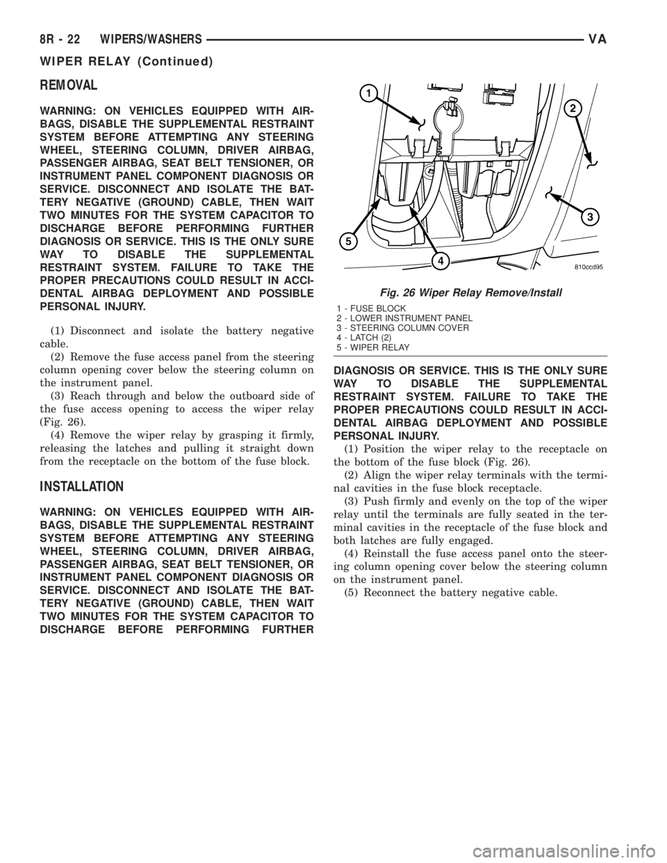
(3) Reach through and below the outboard side of
the fuse access opening to access the wiper relay
(Fig. 26).
(4) Remove the wiper relay by grasping it firmly,
releasing the latches and pulling it straight down
from the receptacle on the bottom of the fuse block.
INSTALLATION
WARNING: ON VEHICLES EQUIPPED WITH AIR-
BAGS, DISABLE THE SUPPLEMENTAL RESTRAINT
SYSTEM BEFORE ATTEMPTING ANY STEERING
WHEEL, STEERING COLUMN, DRIVER AIRBAG,
PASSENGER AIRBAG, SEAT BELT TENSIONER, OR
INSTRUMENT PANEL COMPONENT DIAGNOSIS OR
SERVICE. DISCONNECT AND ISOLATE THE BAT-
TERY NEGATIVE (GROUND) CABLE, THEN WAIT
TWO MINUTES FOR THE SYSTEM CAPACITOR TO
DISCHARGE BEFORE PERFORMING FURTHERDIAGNOSIS OR SERVICE. THIS IS THE ONLY SURE
WAY TO DISABLE THE SUPPLEMENTAL
RESTRAINT SYSTEM. FAILURE TO TAKE THE
PROPER PRECAUTIONS COULD RESULT IN ACCI-
DENTAL AIRBAG DEPLOYMENT AND POSSIBLE
PERSONAL INJURY.
(1) Position the wiper relay to the receptacle on
the bottom of the fuse block (Fig. 26).
(2) Align the wiper relay terminals with the termi-
nal cavities in the fuse block receptacle.
(3) Push firmly and evenly on the top of the wiper
relay until the terminals are fully seated in the ter-
minal cavities in the receptacle of the fuse block and
both latches are fully engaged.
(4) Reinstall the fuse access panel onto the steer-
ing column opening cover below the steering column
on the instrument panel.
(5) Reconnect the battery negative cable.
Fig. 26 Wiper Relay Remove/Install
1 - FUSE BLOCK
2 - LOWER INSTRUMENT PANEL
3 - STEERING COLUMN COVER
4 - LATCH (2)
5 - WIPER RELAY
8R - 22 WIPERS/WASHERSVA
WIPER RELAY (Continued)
Page 307 of 1232
8W-01 WIRING DIAGRAM INFORMATION
TABLE OF CONTENTS
page page
WIRING DIAGRAM INFORMATION
DESCRIPTION
DESCRIPTION - HOW TO USE WIRING
DIAGRAMS...........................1
DESCRIPTION - CIRCUIT INFORMATION....5
DESCRIPTION - SECTION IDENTIFICATION
AND INFORMATION....................5
DESCRIPTION - CONNECTOR, GROUND
AND SPLICE INFORMATION..............5
WARNING
WARNINGS - GENERAL.................6
DIAGNOSIS AND TESTING - WIRING
HARNESS............................6
STANDARD PROCEDURE
STANDARD PROCEDURE -
ELECTROSTATIC DISCHARGE (ESD)
SENSITIVE DEVICES...................7
STANDARD PROCEDURE - TESTING OF
VOLTAGE POTENTIAL...................7
STANDARD PROCEDURE - TESTING FOR
CONTINUITY..........................8STANDARD PROCEDURE - TESTING FOR A
SHORT TO GROUND...................8
STANDARD PROCEDURE - TESTING FOR A
SHORT TO GROUND ON FUSES
POWERING SEVERAL LOADS............8
STANDARD PROCEDURE - TESTING FOR A
VOLTAGE DROP.......................8
CONNECTOR
REMOVAL.............................8
INSTALLATION..........................9
DIODE
REMOVAL.............................9
INSTALLATION..........................9
TERMINAL
REMOVAL.............................9
INSTALLATION.........................10
WIRE
STANDARD PROCEDURE - WIRE SPLICING . . 10
WIRING DIAGRAM
INFORMATION
DESCRIPTION
DESCRIPTION - HOW TO USE WIRING
DIAGRAMS
DaimlerChrysler Corporation wiring diagrams are
designed to provide information regarding the vehi-
cles wiring content. In order to effectively use the
wiring diagrams to diagnose and repair
DaimlerChrysler Corporation vehicles, it is important
to understand all of their features and characteris-
tics.
Diagrams are arranged such that the power (B+)
side of the circuit is placed near the top of the page,
and the ground (B-) side of the circuit is placed near
the bottom of the page (Fig. 1).
All switches, components, and modules are shown
in the at rest position with the doors closed and the
key removed from the ignition (Fig. 2).Components are shown two ways. A solid line
around a component indicates that the component is
complete. A dashed line around the component indi-
cates that the component is being shown is not com-
plete. Incomplete components have a reference
number to indicate the page where the component is
shown complete.
It is important to realize that no attempt is made
on the diagrams to represent components and wiring
as they appear on the vehicle. For example, a short
piece of wire is treated the same as a long one. In
addition, switches and other components are shown
as simply as possible, with regard to function only.
SYMBOLS
International symbols are used throughout the wir-
ing diagrams. These symbols are consistent with
those being used around the world (Fig. 3).
VA8W-01 WIRING DIAGRAM INFORMATION 8W - 01 - 1