2005 MERCEDES-BENZ SPRINTER Cool
[x] Cancel search: CoolPage 873 of 1232
Wipe filler cap clean, then check the fluid level.
The dipstick should indicateCOLDwhen the fluid is
at normal temperature.
(1) Turn steering wheel all the way to the left
(2) Fill the pump fluid reservoir to the proper level
and let the fluid settle for at least two (2) minutes.
(3) Raise the front wheels off the ground.
(4)
Slowly turn the steering wheel lock-to-lock 20
times with the engine off while checking the fluid level.
NOTE: For vehicles with long return lines or oil
coolers turn wheel 40 times.
(5) Start the engine. With the engine idling main-
tain the fluid level.
(6) Lower the front wheels and let the engine idle
for two minutes.
(7) Turn the steering wheel in both direction and
verify power assist and quiet operation of the pump.
If the fluid is extremely foamy or milky looking,
allow the vehicle to stand a few minutes and repeat
the procedure.
CAUTION: Do not run a vehicle with foamy fluid for
an extended period. This may cause pump damage.
STANDARD PROCEDURE - FLUSHING POWER
STEERING SYSTEM
Flushing is required when the power steering/hy-
draulic booster system fluid has become contami-
nated. Contaminated fluid in the steering/booster
system can cause seal deterioration and affect steer-
ing gear/booster spool valve operation.
(1) Raise the front end of the vehicle off the
ground until the wheels are free to turn.
(2) Remove the return line from the pump.
NOTE: If vehicle is equipped with a hydraulic
booster remove both return lines from the pump.
(3) Plug the return line port/ports at the pump.
(4) Position the return line/lines into a large con-
tainer to catch the fluid.
(5) While an assistant is filling the pump reservoir
start the engine.
(6) With the engine running at idle turn the wheel
back and forth.
NOTE: Do not contact or hold the wheel against the
steering stops.
(7) Run a quart of fluid through the system then
stop the engine and install the return line/lines.
(8) Fill the system with fluid and perform Steering
Pump Initial Operation, (Refer to 19 - STEERING/
PUMP - STANDARD PROCEDURE).(9) Start the engine and run it for fifteen minutes
then stop the engine.
(10) Remove the return line/lines from the pump
and plug the pump port/ports.
(11) Pour fresh fluid into the reservoir and check
the draining fluid for contamination. If the fluid is
still contaminated, then flush the system again.
(12) Install the return line/lines and perform
Steering Pump Initial Operation, (Refer to 19 -
STEERING/PUMP - STANDARD PROCEDURE).
REMOVAL
(1) Remove the belt from the power steering pump.
(2) Siphon as much power steering fluid as possi-
ble out of the reservoir.
(3) Remove the high pressure power steering hose
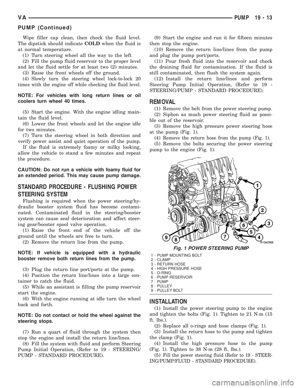
at the pump (Fig. 1).
(4)
Remove the return hose from the pump (Fig. 1).
(5) Remove the bolts securing the power steering
pump to the engine (Fig. 1).
INSTALLATION
(1) Install the power steering pump to the engine
and tighten the bolts (Fig. 1). Tighten to 21 N´m (15
ft. lbs.).
(2) Replace all o-rings and hose clamps (Fig. 1).
(3) Install the return hose to the pump and tighten
the clamp (Fig. 1).
(4) Install the high pressure hose to the pump
(Fig. 1). Tighten to 38 N´m (28 ft. lbs.).
(5)
Fill the power steering fluid (Refer to 19 - STEER-
ING/PUMP/FLUID - STANDARD PROCEDURE).
Fig. 1 POWER STEERING PUMP
1 - PUMP MOUNTING BOLT
2 - CLAMP
3 - RETURN HOSE
4 - HIGH PRESSURE HOSE
5 - O-RING
6 - PUMP RESERVOIR
7 - PUMP
8 - PULLEY
9 - PULLEY BOLT
VAPUMP 19 - 13
PUMP (Continued)
Page 874 of 1232
SPECIFICATIONS - TORQUE CHART
TORQUE SPECIFICATIONS
DESCRIPTION N´m Ft. Lbs. In. Lbs.
Power Steering Pump To
Timing Case Cover/
Support21 15 185
High Pressure Flexible
Hose To Power Steering
Pump38 28 336
Power Steering Pulley To
Pump30 22 265
FLUID
STANDARD PROCEDURE
POWER STEERING PUMP FILL AND BLEED
PROCEDURE
(1) Remove the cap from the fluid reservoir.
Check cap seal for damage and replace if
needed.
(2) Fill the power steering pump with Mopar
ATF+4 Automatic Transmission fluid or equivalent.
Do not fill fluid beyond the MAX mark.
(3) Raise the vehicles front wheels off the ground.
(4) With the engine off turn the steering wheel
from right to left.Perform this step until all the
bubble formations can no longer be seen in the
power steering reservoir.
(5) Start the engine and turn the steering wheel
with the engine at idle speed then shut the engine off
and check for correct oil level and no bubble in the
system.
(6) Reinstall power steering cap tightly.
(7) Test the system for leaks and proper operation.
FLUID COOLER TUBE
REMOVAL
(1) Siphon as much power steering fluid as possi-
ble out of the reservoir.
(2) Remove the grille (Refer to 23 - BODY/EXTE-
RIOR/GRILLE - REMOVAL).
(3) Remove the left headlight assembly.
(4) Disconnect the return lines from the cooler
tube.
(5) Remove the radiator clips (2).
(6) Remove the heat shield bolt for the turbo at
the core support.
(7) Remove the right headlight assembly.(8) Remove the core support bolts (4) and discon-
nect the hood latch cable.
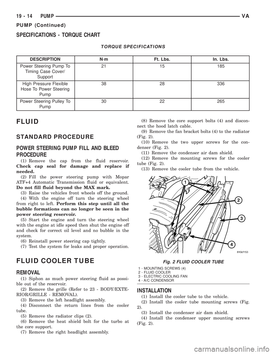
(9) Remove the fan bracket bolts (4) to the radiator
(Fig. 2).
(10) Remove the two upper screws for the con-
denser (Fig. 2).
(11) Remove the condenser air dam shield.
(12) Remove the mounting screws for the cooler
tube (Fig. 2).
(13) Remove the cooler tube from the vehicle.
INSTALLATION
(1) Install the cooler tube to the vehicle.
(2) Install the cooler tube mounting screws (Fig.
2).
(3) Install the condenser air dam shield.
(4) Install the condenser upper mounting screws
(Fig. 2).
Fig. 2 FLUID COOLER TUBE
1 - MOUNTING SCREWS (4)
2 - FLUID COOLER
3 - ELECTRIC COOLING FAN
4 - A/C CONDENSOR
19 - 14 PUMPVA
PUMP (Continued)
Page 875 of 1232
(5) Install the fan bracket bolts to the radiator
(Fig. 2).
(6) Install the core support bolts and reconnect the
hood latch cable.
(7) Install the right headlight assembly.
(8) Install the bolt for the turbo shield at the core
support.
(9) Install the radiator clips.
(10) Install the return lines to the cooler tube.
(11) Install the left headlight assembly.
(12) Install the grille assembly (Refer to 23 -
BODY/EXTERIOR/GRILLE - INSTALLATION).
(13) Fill the power steering fluid (Refer to 19 -
STEERING/PUMP/FLUID - STANDARD PROCE-
DURE).
HOSES
REMOVAL
REMOVAL - PRESSURE HOSE
(1) Siphon as much power steering fluid as possi-
ble out of the reservoir.
(2) Disconnect the pressure hose at the pump.
(3) Disconnect the pressure hose at the steering
gear.
(4) Remove the pressure hose mounting bracket
from the gear.
(5) Remove the pressure hose from the vehicle.
REMOVAL - RETURN LINE FROM PUMP TO
COOLER TUBE
(1) Siphon as much power steering fluid as possi-
ble out of the reservoir.
(2) Disconnect the return line at the pump.
(3) Remove the grille (Refer to 23 - BODY/EXTE-
RIOR/GRILLE - REMOVAL).
(4) Remove the left headlight assembly.
(5) Disconnect the return line at the cooler tube.
(6) Remove the return line from the vehicle.
REMOVAL - RETURN HOSE FROM GEAR TO
COOLER TUBE
(1) Siphon as much power steering fluid as possi-
ble out of the reservoir.
(2) Disconnect the return hose from the gear.(3) Remove the grille (Refer to 23 - BODY/EXTE-
RIOR/GRILLE - REMOVAL).
(4) Remove the left headlight assembly.
(5) Disconnect the return line at the cooler tube.
(6) Remove the return line from the vehicle.
INSTALLATION
INSTALLATION - PRESSURE HOSE
(1) Install the pressure hose to the vehicle.
(2) Reconnect the pressure hose at the steering
gear. Tighten to 37 N´m (27 ft.lbs.).
(3) Install the pressure hose mounting bracket to
the steering gear.
(4) Reconnect the pressure hose at the power
steering pump. Tighten to 38 N´m (28 ft.lbs.).
(5) Fill the power steering fluid (Refer to 19 -
STEERING/PUMP/FLUID - STANDARD PROCE-
DURE).
INSTALLATION - RETURN LINE FROM PUMP
TO COOLER TUBE
(1) Install the return line to the vehicle.
(2) Reconnect the return line at the cooler tube.
(3) Install the left headlight assembly.
(4) Install the grille assembly (Refer to 23 - BODY/
EXTERIOR/GRILLE - INSTALLATION).
(5) Reconnect the return line at the power steering
pump.
(6) Fill the power steering fluid (Refer to 19 -
STEERING/PUMP/FLUID - STANDARD PROCE-
DURE).
INSTALLATION - RETURN HOSE FROM GEAR
TO COOLER TUBE
(1) Install the return line to the vehicle.
(2) Reconnect the return line at the cooler tube.
(3) Install the left headlight assembly.
(4) Install the grille assembly (Refer to 23 - BODY/
EXTERIOR/GRILLE - INSTALLATION).
(5) Reconnect the return line at the power steering
gear.
(6) Fill the power steering fluid (Refer to 19 -
STEERING/PUMP/FLUID - STANDARD
PROCEDURE).
VAPUMP 19 - 15
FLUID COOLER TUBE (Continued)
Page 899 of 1232
DIAGNOSIS AND TESTING
DIAGNOSIS AND TESTING - AUTOMATIC
TRANSMISSION
CAUTION: Before attempting any repair on a NAG1
automatic transmission, check for Diagnostic Trou-
ble Codes with the DRBTscan tool.
Transmission malfunctions may be caused by these
general conditions:
²Poor engine performance.
²Improper adjustments.
²Hydraulic malfunctions.
²Mechanical malfunctions.
²Electronic malfunctions.
²Transfer case performance.
Diagnosis of these problems should always begin
by checking the easily accessible variables: fluid level
and condition, gearshift cable adjustment. Then per-
form a road test to determine if the problem has been
corrected or if more diagnosis is necessary.
DIAGNOSIS AND TESTING - PRELIMINARY
Two basic procedures are required. One procedure
for vehicles that are drivable and an alternate proce-
dure for disabled vehicles (will not back up or move
forward).
VEHICLE IS DRIVABLE
(1) Check for transmission fault codes using DRBt
scan tool.
(2) Check fluid level and condition.
(3) Adjust gearshift cable if complaint was based
on delayed, erratic, or harsh shifts.
(4) Road test and note how transmission upshifts,
downshifts, and engages.
VEHICLE IS DISABLED
(1) Check fluid level and condition.(2) Check for broken or disconnected gearshift
cable.
(3) Check for cracked, leaking cooler lines, or loose
or missing pressure-port plugs.
(4) Raise and support vehicle on safety stands,
start engine, shift transmission into gear, and note
following:
(a) If propeller shaft turns but wheels do not,
problem is with differential or axle shafts.
(b) If propeller shaft does not turn and transmis-
sion is noisy, stop engine. Remove oil pan, and
check for debris. If pan is clear, remove transmis-
sion and check for damaged driveplate, converter,
oil pump, or input shaft.
(c) If propeller shaft does not turn and transmis-
sion is not noisy, perform hydraulic-pressure test to
determine if problem is hydraulic or mechanical.
DIAGNOSIS AND TESTING - ROAD TESTING
Before road testing, be sure the fluid level and con-
trol cable adjustments have been checked and
adjusted if necessary. Verify that all diagnostic trou-
ble codes have been resolved.
Observe engine performance during the road test.
A poorly tuned engine will not allow accurate analy-
sis of transmission operation.
Operate the transmission in all gear ranges. Check
for shift variations and engine flare which indicates
slippage. Note if shifts are harsh, spongy, delayed,
early, or if part throttle downshifts are sensitive.
Slippage indicated by engine flare, usually means
clutch, overrunning clutch, or line pressure problems.
A slipping clutch can often be determined by com-
paring which internal units are applied in the vari-
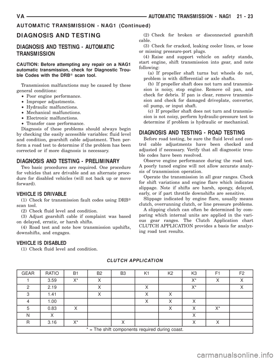
ous gear ranges. The Clutch Application chart
CLUTCH APPLICATION provides a basis for analyz-
ing road test results.
CLUTCH APPLICATION
GEAR RATIO B1 B2 B3 K1 K2 K3 F1 F2
1 3.59 X* X X* X X
2 2.19 X X X* X
3 1.41 X X X
4 1.00 X X X
5 0.83 X X X X*
NX X
R 3.16 X* X X X
* = The shift components required during coast.
VAAUTOMATIC TRANSMISSION - NAG1 21 - 23
AUTOMATIC TRANSMISSION - NAG1 (Continued)
Page 903 of 1232
STANDARD PROCEDURE - ALUMINUM
THREAD REPAIR
Damaged or worn threads in the aluminum trans-
mission case and valve body can be repaired by the
use of Heli-CoilsŸ, or equivalent. This repair con-
sists of drilling out the worn-out damaged threads.
Then tap the hole with a special Heli-CoilŸ tap, or
equivalent, and installing a Heli-CoilŸ insert, or
equivalent, into the hole. This brings the hole back to
its original thread size.
Heli-CoilŸ, or equivalent, tools and inserts are
readily available from most automotive parts suppli-
ers.
REMOVAL
(1) Disconnect the negative (ground) battery cable.
CAUTION: Isolate ground lead to prevent accidental
contact.
(2) Apply parking brake.
(3) Move gear selector lever to position9N9.
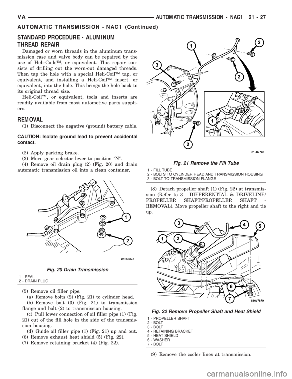
(4) Remove oil drain plug (2) (Fig. 20) and drain
automatic transmission oil into a clean container.
(5) Remove oil filler pipe.
(a) Remove bolts (2) (Fig. 21) to cylinder head.
(b) Remove bolt (3) (Fig. 21) to transmission
flange and bolt (2) to transmission housing.
(c) Pull lower connection of oil filler pipe (1) (Fig.
21) out of the fill hole in the side of the transmis-
sion housing.
(d) Guide oil filler pipe (1) (Fig. 21) up and out.
(6) Remove exhaust heat shield (5) (Fig. 22).
(7) Remove retaining bracket (4) (Fig. 22).(8) Detach propeller shaft (1) (Fig. 22) at transmis-
sion (Refer to 3 - DIFFERENTIAL & DRIVELINE/
PROPELLER SHAFT/PROPELLER SHAFT -
REMOVAL). Move propeller shaft to the right and tie
up.
(9) Remove the cooler lines at transmission.
Fig. 20 Drain Transmission
1 - SEAL
2 - DRAIN PLUG
Fig. 21 Remove the Fill Tube
1 - FILL TUBE
2 - BOLTS TO CYLINDER HEAD AND TRANSMISSION HOUSING
3 - BOLT TO TRANSMISSION FLANGE
Fig. 22 Remove Propeller Shaft and Heat Shield
1 - PROPELLER SHAFT
2 - BOLT
3 - BOLT
4 - RETAINING BRACKET
5 - HEAT SHIELD
6 - WASHER
7 - BOLT
VAAUTOMATIC TRANSMISSION - NAG1 21 - 27
AUTOMATIC TRANSMISSION - NAG1 (Continued)
Page 904 of 1232
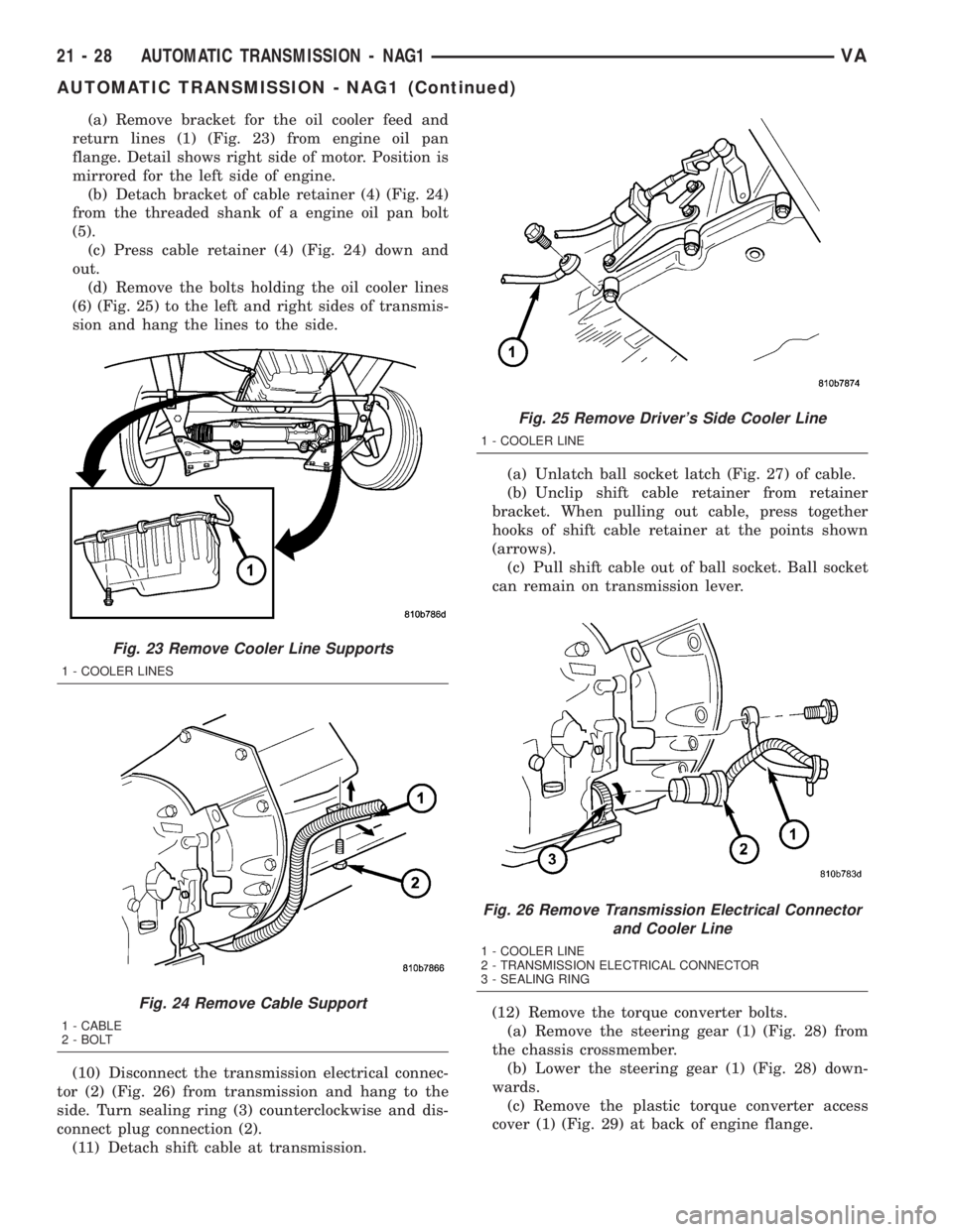
(a) Remove bracket for the oil cooler feed and
return lines (1) (Fig. 23) from engine oil pan
flange. Detail shows right side of motor. Position is
mirrored for the left side of engine.
(b) Detach bracket of cable retainer (4) (Fig. 24)
from the threaded shank of a engine oil pan bolt
(5).
(c) Press cable retainer (4) (Fig. 24) down and
out.
(d) Remove the bolts holding the oil cooler lines
(6) (Fig. 25) to the left and right sides of transmis-
sion and hang the lines to the side.
(10) Disconnect the transmission electrical connec-
tor (2) (Fig. 26) from transmission and hang to the
side. Turn sealing ring (3) counterclockwise and dis-
connect plug connection (2).
(11) Detach shift cable at transmission.(a) Unlatch ball socket latch (Fig. 27) of cable.
(b) Unclip shift cable retainer from retainer
bracket. When pulling out cable, press together
hooks of shift cable retainer at the points shown
(arrows).
(c) Pull shift cable out of ball socket. Ball socket
can remain on transmission lever.
(12) Remove the torque converter bolts.
(a) Remove the steering gear (1) (Fig. 28) from
the chassis crossmember.
(b) Lower the steering gear (1) (Fig. 28) down-
wards.
(c) Remove the plastic torque converter access
cover (1) (Fig. 29) at back of engine flange.
Fig. 23 Remove Cooler Line Supports
1 - COOLER LINES
Fig. 24 Remove Cable Support
1 - CABLE
2 - BOLT
Fig. 25 Remove Driver's Side Cooler Line
1 - COOLER LINE
Fig. 26 Remove Transmission Electrical Connector
and Cooler Line
1 - COOLER LINE
2 - TRANSMISSION ELECTRICAL CONNECTOR
3 - SEALING RING
21 - 28 AUTOMATIC TRANSMISSION - NAG1VA
AUTOMATIC TRANSMISSION - NAG1 (Continued)
Page 920 of 1232
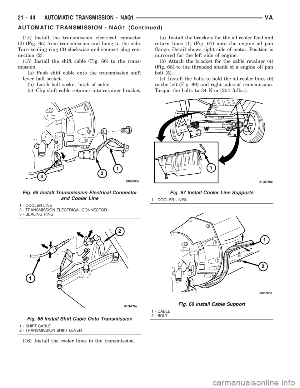
(14) Install the transmission electrical connector
(2) (Fig. 65) from transmission and hang to the side.
Turn sealing ring (3) clockwise and connect plug con-
nection (2).
(15) Install the shift cable (Fig. 66) to the trans-
mission.
(a) Push shift cable onto the transmission shift
lever ball socket.
(b) Latch ball socket latch of cable.
(c) Clip shift cable retainer into retainer bracket.
(16) Install the cooler lines to the transmission.(a) Install the brackets for the oil cooler feed and
return lines (1) (Fig. 67) onto the engine oil pan
flange. Detail shows right side of motor. Position is
mirrored for the left side of engine.
(b) Attach the bracket for the cable retainer (4)
(Fig. 68) to the threaded shank of a engine oil pan
bolt (5).
(c) Install the bolts to hold the oil cooler lines (6)
to the left (Fig. 69) and right sides of transmission.
Torque the bolts to 34 N´m (254 ft.lbs.).
Fig. 65 Install Transmission Electrical Connector
and Cooler Line
1 - COOLER LINE
2 - TRANSMISSION ELECTRICAL CONNECTOR
3 - SEALING RING
Fig. 66 Install Shift Cable Onto Transmission
1 - SHIFT CABLE
2 - TRANSMISSION SHIFT LEVER
Fig. 67 Install Cooler Line Supports
1 - COOLER LINES
Fig. 68 Install Cable Support
1 - CABLE
2 - BOLT
21 - 44 AUTOMATIC TRANSMISSION - NAG1VA
AUTOMATIC TRANSMISSION - NAG1 (Continued)
Page 921 of 1232
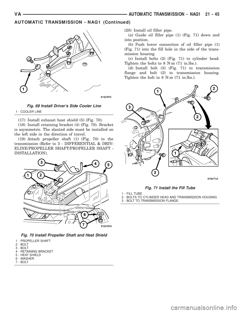
(17) Install exhaust heat shield (5) (Fig. 70).
(18) Install retaining bracket (4) (Fig. 70). Bracket
is asymmetric. The slanted side must be installed on
the left side in the direction of travel.
(19) Attach propeller shaft (1) (Fig. 70) to the
transmission (Refer to 3 - DIFFERENTIAL & DRIV-
ELINE/PROPELLER SHAFT/PROPELLER SHAFT -
INSTALLATION).(20) Install oil filler pipe.
(a) Guide oil filler pipe (1) (Fig. 71) down and
into position.
(b) Push lower connection of oil filler pipe (1)
(Fig. 71) into the fill hole in the side of the trans-
mission housing.
(c) Install bolts (2) (Fig. 71) to cylinder head.
Tighten the bolts to 8 N´m (71 in.lbs.).
(d) Install bolt (3) (Fig. 71) to transmission
flange and bolt (2) to transmission housing.
Tighten the bolt to 8 N´m (71 in.lbs.).
Fig. 69 Install Driver's Side Cooler Line
1 - COOLER LINE
Fig. 70 Install Propeller Shaft and Heat Shield
1 - PROPELLER SHAFT
2 - BOLT
3 - BOLT
4 - RETAINING BRACKET
5 - HEAT SHIELD
6 - WASHER
7 - BOLT
Fig. 71 Install the Fill Tube
1 - FILL TUBE
2 - BOLTS TO CYLINDER HEAD AND TRANSMISSION HOUSING
3 - BOLT TO TRANSMISSION FLANGE
VAAUTOMATIC TRANSMISSION - NAG1 21 - 45
AUTOMATIC TRANSMISSION - NAG1 (Continued)