2005 MERCEDES-BENZ SPRINTER Cool
[x] Cancel search: CoolPage 958 of 1232
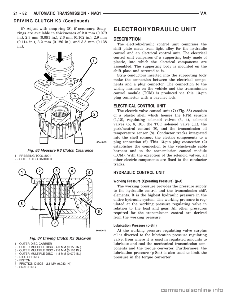
(f) Adjust with snap-ring (8), if necessary. Snap-
rings are available in thicknesses of 2.0 mm (0.079
in.), 2.3 mm (0.091 in.), 2.6 mm (0.102 in.), 2.9 mm
(0.114 in.), 3.2 mm (0.126 in.), and 3.5 mm (0.138
in.).ELECTROHYDRAULIC UNIT
DESCRIPTION
The electrohydraulic control unit comprises the
shift plate made from light alloy for the hydraulic
control and an electrical control unit. The electrical
control unit comprises of a supporting body made of
plastic, into which the electrical components are
assembled. The supporting body is mounted on the
shift plate and screwed to it.
Strip conductors inserted into the supporting body
make the connection between the electrical compo-
nents and a plug connector. The connection to the
wiring harness on the vehicle and the transmission
control module (TCM) is produced via this 13-pin
plug connector with a bayonet lock.
ELECTRICAL CONTROL UNIT
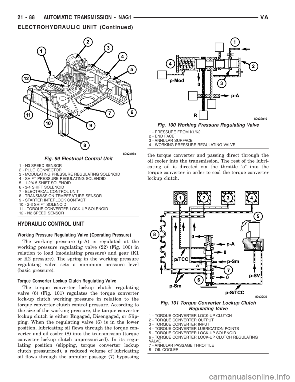
The electric valve control unit (7) (Fig. 88) consists
of a plastic shell which houses the RPM sensors
(1,12), regulating solenoid valves (3, 4), solenoid
valves (5, 6, 10), the TCC solenoid valve (11), the
park/neutral contact (9), and the transmission oil
temperature sensor (8). Conductor tracks integrated
into the shell connect the electric components to a
plug connection (2). This 13-pin plug connection (2)
establishes the connection to the vehicle-side cable
harness and to the transmission control module
(TCM). With the exception of the solenoid valves, all
other electric components are fixed to the conductor
tracks.
HYDRAULIC CONTROL UNIT
Working Pressure (Operating Pressure) (p-A)
The working pressure provides the pressure supply
to the hydraulic control and the transmission shift
elements. It is the highest hydraulic pressure in the
entire hydraulic system. The working pressure is reg-
ulated at the working pressure regulating valve in
relation to the load and gear. All other pressures
required for the transmission control are derived
from the working pressure.
Lubrication Pressure (p-Sm)
At the working pressure regulating valve surplus
oil is diverted to the lubrication pressure regulating
valve, from where it is used in regulated amounts to
lubricate and cool the mechanical transmission com-
ponents and the torque converter. Furthermore, the
lubrication pressure (p-Sm) is also used to limit the
pressure in the torque converter.
Fig. 86 Measure K3 Clutch Clearance
1 - PRESSING TOOL 8901
2 - OUTER DISC CARRIER
Fig. 87 Driving Clutch K3 Stack-up
1 - OUTER DISC CARRIER
2 - OUTER MULTIPLE DISC - 4.0 MM (0.158 IN.)
3 - OUTER MULTIPLE DISC - 2.8 MM (0.110 IN.)
4 - OUTER MULTIPLE DISC - 1.8 MM (0.079 IN.)
5 - DISC SPRING
6 - PISTON
7 - FRICTION DISCS - 2.1 MM (0.083 IN.)
8 - SNAP-RING
21 - 82 AUTOMATIC TRANSMISSION - NAG1VA
DRIVING CLUTCH K3 (Continued)
Page 960 of 1232
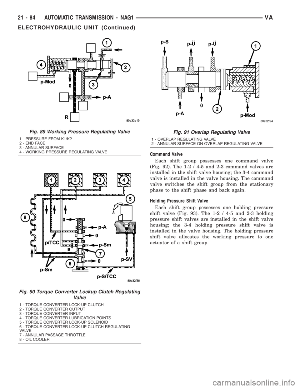
Command Valve
Each shift group possesses one command valve
(Fig. 92). The 1-2 / 4-5 and 2-3 command valves are
installed in the shift valve housing; the 3-4 command
valve is installed in the valve housing. The command
valve switches the shift group from the stationary
phase to the shift phase and back again.
Holding Pressure Shift Valve
Each shift group possesses one holding pressure
shift valve (Fig. 93). The 1-2 / 4-5 and 2-3 holding
pressure shift valves are installed in the shift valve
housing; the 3-4 holding pressure shift valve is
installed in the valve housing. The holding pressure
shift valve allocates the working pressure to one
actuator of a shift group.
Fig. 89 Working Pressure Regulating Valve
1 - PRESSURE FROM K1/K2
2 - END FACE
3 - ANNULAR SURFACE
4 - WORKING PRESSURE REGULATING VALVE
Fig. 90 Torque Converter Lockup Clutch Regulating
Valve
1 - TORQUE CONVERTER LOCK-UP CLUTCH
2 - TORQUE CONVERTER OUTPUT
3 - TORQUE CONVERTER INPUT
4 - TORQUE CONVERTER LUBRICATION POINTS
5 - TORQUE CONVERTER LOCK-UP SOLENOID
6 - TORQUE CONVERTER LOCK-UP CLUTCH REGULATING
VA LV E
7 - ANNULAR PASSAGE THROTTLE
8 - OIL COOLER
Fig. 91 Overlap Regulating Valve
1 - OVERLAP REGULATING VALVE
2 - ANNULAR SURFACE ON OVERLAP REGULATING VALVE
21 - 84 AUTOMATIC TRANSMISSION - NAG1VA
ELECTROHYDRAULIC UNIT (Continued)
Page 962 of 1232
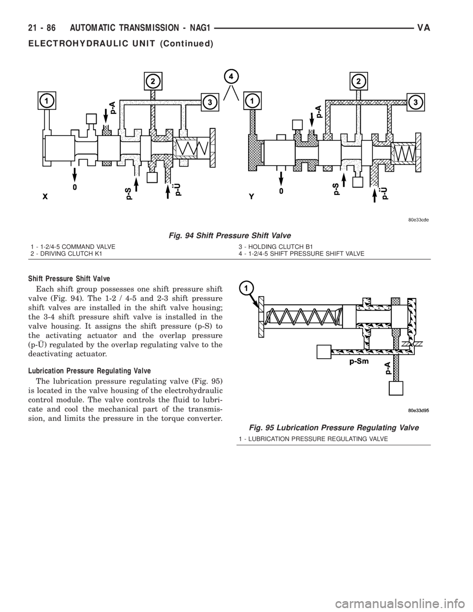
Shift Pressure Shift Valve
Each shift group possesses one shift pressure shift
valve (Fig. 94). The 1-2 / 4-5 and 2-3 shift pressure
shift valves are installed in the shift valve housing;
the 3-4 shift pressure shift valve is installed in the
valve housing. It assigns the shift pressure (p-S) to
the activating actuator and the overlap pressure
(p-š) regulated by the overlap regulating valve to the
deactivating actuator.
Lubrication Pressure Regulating Valve
The lubrication pressure regulating valve (Fig. 95)
is located in the valve housing of the electrohydraulic
control module. The valve controls the fluid to lubri-
cate and cool the mechanical part of the transmis-
sion, and limits the pressure in the torque converter.
Fig. 94 Shift Pressure Shift Valve
1 - 1-2/4-5 COMMAND VALVE
2 - DRIVING CLUTCH K13 - HOLDING CLUTCH B1
4 - 1-2/4-5 SHIFT PRESSURE SHIFT VALVE
Fig. 95 Lubrication Pressure Regulating Valve
1 - LUBRICATION PRESSURE REGULATING VALVE
21 - 86 AUTOMATIC TRANSMISSION - NAG1VA
ELECTROHYDRAULIC UNIT (Continued)
Page 964 of 1232
HYDRAULIC CONTROL UNIT
Working Pressure Regulating Valve (Operating Pressure)
The working pressure (p-A) is regulated at the
working pressure regulating valve (22) (Fig. 100) in
relation to load (modulating pressure) and gear (K1
or K2 pressure). The spring in the working pressure
regulating valve sets a minimum pressure level
(basic pressure).
Torque Converter Lockup Clutch Regulating Valve
The torque converter lockup clutch regulating
valve (6) (Fig. 101) regulates the torque converter
lock-up clutch working pressure in relation to the
torque converter clutch control pressure. According to
the size of the working pressure, the torque converter
lockup clutch is either Engaged, Disengaged, or Slip-
ping. When the regulating valve (6) is in the lower
position, lubricating oil flows through the torque con-
verter and oil cooler (8) into the transmission (torque
converter lockup clutch unpressurized). In its regu-
lating position (slipping, torque converter lockup
clutch pressurized), a reduced volume of lubricating
oil flows through the annular passage (7) bypassingthe torque converter and passing direct through the
oil cooler into the transmission. The rest of the lubri-
cating oil is directed via the throttle9a9into the
torque converter in order to cool the torque converter
lockup clutch.
Fig. 99 Electrical Control Unit
1 - N3 SPEED SENSOR
2 - PLUG CONNECTOR
3 - MODULATING PRESSURE REGULATING SOLENOID
4 - SHIFT PRESSURE REGULATING SOLENOID
5 - 1-2/4-5 SHIFT SOLENOID
6 - 3-4 SHIFT SOLENOID
7 - ELECTRICAL CONTROL UNIT
8 - TRANSMISSION TEMPERATURE SENSOR
9 - STARTER INTERLOCK CONTACT
10 - 2-3 SHIFT SOLENOID
11 - TORQUE CONVERTER LOCK-UP SOLENOID
12 - N2 SPEED SENSOR
Fig. 100 Working Pressure Regulating Valve
1 - PRESSURE FROM K1/K2
2 - END FACE
3 - ANNULAR SURFACE
4 - WORKING PRESSURE REGULATING VALVE
Fig. 101 Torque Converter Lockup Clutch
Regulating Valve
1 - TORQUE CONVERTER LOCK-UP CLUTCH
2 - TORQUE CONVERTER OUTPUT
3 - TORQUE CONVERTER INPUT
4 - TORQUE CONVERTER LUBRICATION POINTS
5 - TORQUE CONVERTER LOCK-UP SOLENOID
6 - TORQUE CONVERTER LOCK-UP CLUTCH REGULATING
VA LV E
7 - ANNULAR PASSAGE THROTTLE
8 - OIL COOLER
21 - 88 AUTOMATIC TRANSMISSION - NAG1VA
ELECTROHYDRAULIC UNIT (Continued)
Page 968 of 1232
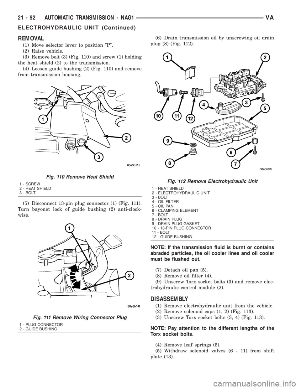
REMOVAL
(1) Move selector lever to position9P9.
(2) Raise vehicle.
(3) Remove bolt (3) (Fig. 110) and screw (1) holding
the heat shield (2) to the transmission.
(4) Loosen guide bushing (2) (Fig. 110) and remove
from transmission housing.
(5) Disconnect 13-pin plug connector (1) (Fig. 111).
Turn bayonet lock of guide bushing (2) anti-clock-
wise.(6) Drain transmission oil by unscrewing oil drain
plug (8) (Fig. 112).
NOTE: If the transmission fluid is burnt or contains
abraded particles, the oil cooler lines and oil cooler
must be flushed out.
(7) Detach oil pan (5).
(8) Remove oil filter (4).
(9) Unscrew Torx socket bolts (3) and remove elec-
trohydraulic control module (2).
DISASSEMBLY
(1) Remove electrohydraulic unit from the vehicle.
(2) Remove solenoid caps (1, 2) (Fig. 113).
(3) Unscrew Torx socket bolts (3, 4) (Fig. 113).
NOTE: Pay attention to the different lengths of the
Torx socket bolts.
(4) Remove leaf springs (5).
(5) Withdraw solenoid valves (6 - 11) from shift
plate (13).
Fig. 110 Remove Heat Shield
1 - SCREW
2 - HEAT SHIELD
3 - BOLT
Fig. 111 Remove Wiring Connector Plug
1 - PLUG CONNECTOR
2 - GUIDE BUSHING
Fig. 112 Remove Electrohydraulic Unit
1 - HEAT SHIELD
2 - ELECTROHYDRAULIC UNIT
3 - BOLT
4 - OIL FILTER
5 - OIL PAN
6 - CLAMPING ELEMENT
7 - BOLT
8 - DRAIN PLUG
9 - DRAIN PLUG GASKET
10 - 13-PIN PLUG CONNECTOR
11 - BOLT
12 - GUIDE BUSHING
21 - 92 AUTOMATIC TRANSMISSION - NAG1VA
ELECTROHYDRAULIC UNIT (Continued)
Page 978 of 1232
DIAGNOSIS AND TESTING
DIAGNOSIS AND TESTING - EFFECTS OF
INCORRECT FLUID LEVEL
A low fluid level allows the pump to take in air
along with the fluid. Air in the fluid will cause fluid
pressures to be low and develop slower than normal.
If the transmission is overfilled, the gears churn the
fluid into foam. This aerates the fluid and causing
the same conditions occurring with a low level. In
either case, air bubbles cause fluid overheating, oxi-
dation and varnish buildup which interferes with
valve and clutch operation. Foaming also causes fluid
expansion which can result in fluid overflow from the
transmission vent or fill tube. Fluid overflow can eas-
ily be mistaken for a leak if inspection is not careful.
DIAGNOSIS AND TESTING - CAUSES OF
BURNT FLUID
Burnt, discolored fluid is a result of overheating
which has three primary causes.
(1) Internal clutch slippage, usually caused by low
line pressure, inadequate clutch apply pressure, or
clutch seal failure.
(2) A result of restricted fluid flow through the
main and/or auxiliary cooler. This condition is usu-
ally the result of a faulty or improperly installed
drainback valve, a damaged main cooler, or severe
restrictions in the coolers and lines caused by debris
or kinked lines.
(3) Heavy duty operation with a vehicle not prop-
erly equipped for this type of operation. Trailer tow-
ing or similar high load operation will overheat the
transmission fluid if the vehicle is improperly
equipped. Such vehicles should have an auxiliary
transmission fluid cooler, a heavy duty cooling sys-
tem, and the engine/axle ratio combination needed to
handle heavy loads.
DIAGNOSIS AND TESTING - FLUID
CONTAMINATION
Transmission fluid contamination is generally a
result of:
²adding incorrect fluid
²failure to clean dipstick and fill tube when
checking level
²engine coolant entering the fluid
²internal failure that generates debris
²overheat that generates sludge (fluid break-
down)
²failure to replace contaminated converter after
repair
The use of non-recommended fluids can result in
transmission failure. The usual results are erratic
shifts, slippage, abnormal wear and eventual failuredue to fluid breakdown and sludge formation. Avoid
this condition by using recommended fluids only.
The dipstick cap and fill tube should be wiped
clean before checking fluid level. Dirt, grease and
other foreign material on the cap and tube could fall
into the tube if not removed beforehand. Take the
time to wipe the cap and tube clean before withdraw-
ing the dipstick.
Engine coolant in the transmission fluid is gener-
ally caused by a cooler malfunction. The only remedy
is to replace the radiator as the cooler in the radiator
is not a serviceable part. If coolant has circulated
through the transmission, an overhaul is necessary.
The torque converter should be replaced whenever
a failure generates sludge and debris. This is neces-
sary because normal converter flushing procedures
will not remove all contaminants.
STANDARD PROCEDURE
STANDARD PROCEDURE - CHECK OIL LEVEL
(1) Verify that the vehicle is parked on a level sur-
face.
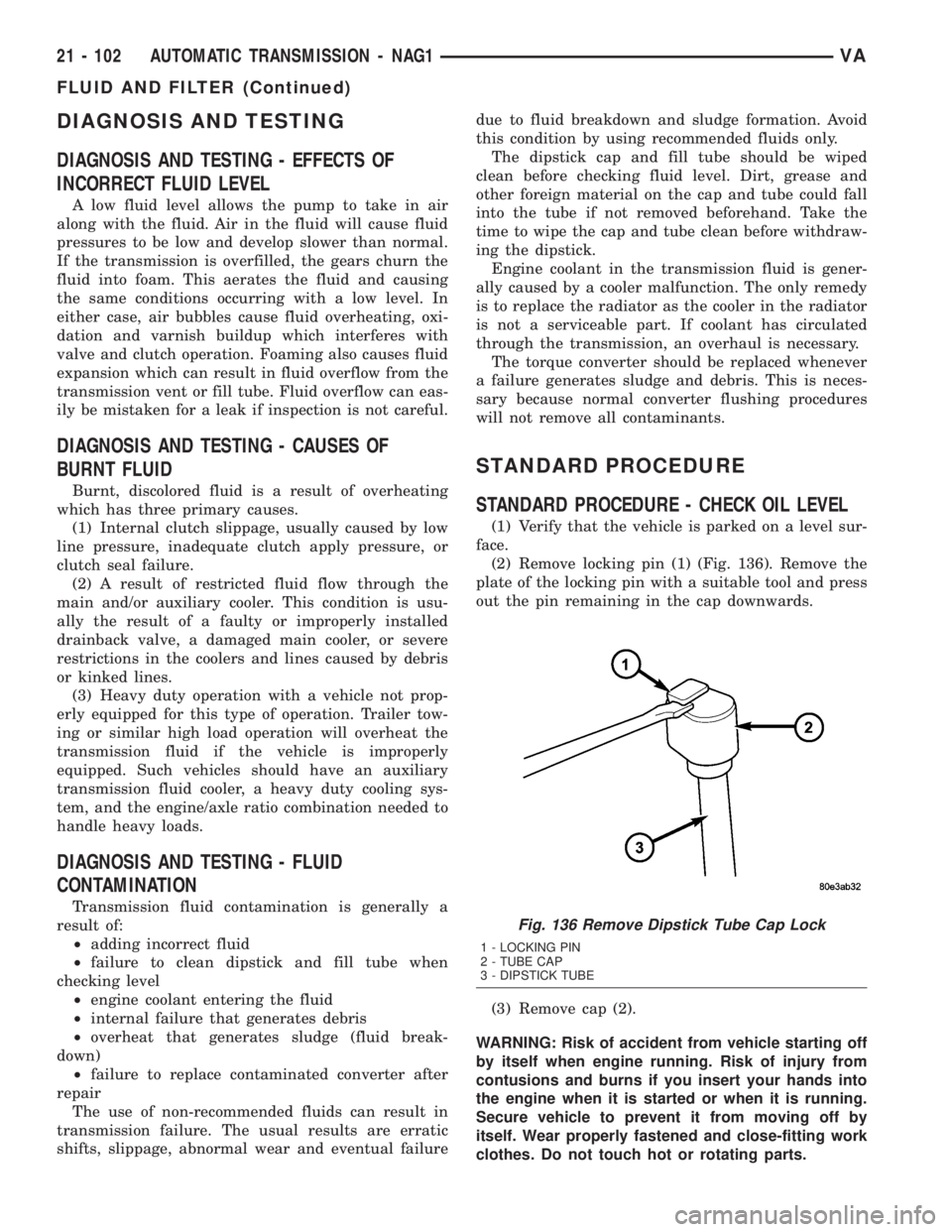
(2) Remove locking pin (1) (Fig. 136). Remove the
plate of the locking pin with a suitable tool and press
out the pin remaining in the cap downwards.
(3) Remove cap (2).
WARNING: Risk of accident from vehicle starting off
by itself when engine running. Risk of injury from
contusions and burns if you insert your hands into
the engine when it is started or when it is running.
Secure vehicle to prevent it from moving off by
itself. Wear properly fastened and close-fitting work
clothes. Do not touch hot or rotating parts.
Fig. 136 Remove Dipstick Tube Cap Lock
1 - LOCKING PIN
2 - TUBE CAP
3 - DIPSTICK TUBE
21 - 102 AUTOMATIC TRANSMISSION - NAG1VA
FLUID AND FILTER (Continued)
Page 980 of 1232
(a) If only fluid and filter were changed, add5.0
L (10.6 pts.)of transmission fluid to transmission.
(b) If transmission was completely overhauled,
torque converter was replaced or drained, and
cooler was flushed, add7.7 L (16.3 pts.)of trans-
mission fluid to transmission.
(5) Check the transmission fluid (Refer to 21 -
TRANSMISSION/AUTOMATIC - NAG1/FLUID -
STANDARD PROCEDURE) and adjust as required.
STANDARD PROCEDURE - FLUID/FILTER
SERVICE
(1) Run the engine until the transmission oil
reaches operating temperature.
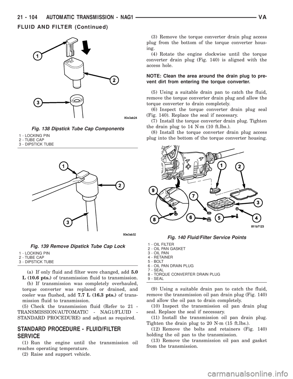
(2) Raise and support vehicle.(3) Remove the torque converter drain plug access
plug from the bottom of the torque converter hous-
ing.
(4) Rotate the engine clockwise until the torque
converter drain plug (Fig. 140) is aligned with the
access hole.
NOTE: Clean the area around the drain plug to pre-
vent dirt from entering the torque converter.
(5) Using a suitable drain pan to catch the fluid,
remove the torque converter drain plug and allow the
torque converter to drain completely.
(6) Inspect the torque converter drain plug seal
(Fig. 140). Replace the seal if necessary.
(7) Install the torque converter drain plug. Tighten
the drain plug to 14 N´m (10 ft.lbs.).
(8) Install the torque converter drain plug access
plug into the bottom of the torque converter housing.
(9) Using a suitable drain pan to catch the fluid,
remove the transmission oil pan drain plug (Fig. 140)
and allow the oil pan to drain completely.
(10) Inspect the transmission oil pan drain plug
seal. Replace the seal if necessary.
(11) Install the transmission oil pan drain plug.
Tighten the drain plug to 20 N´m (15 ft.lbs.).
(12) Remove the bolts and retainers (Fig. 140)
holding the oil pan to the transmission.
(13) Remove the transmission oil pan and gasket
from the transmission.
Fig. 138 Dipstick Tube Cap Components
1 - LOCKING PIN
2 - TUBE CAP
3 - DIPSTICK TUBE
Fig. 139 Remove Dipstick Tube Cap Lock
1 - LOCKING PIN
2 - TUBE CAP
3 - DIPSTICK TUBE
Fig. 140 Fluid/Filter Service Points
1 - OIL FILTER
2 - OIL PAN GASKET
3 - OIL PAN
4 - RETAINER
5 - BOLT
6 - OIL PAN DRAIN PLUG
7 - SEAL
8 - TORQUE CONVERTER DRAIN PLUG
9 - SEAL
21 - 104 AUTOMATIC TRANSMISSION - NAG1VA
FLUID AND FILTER (Continued)
Page 1019 of 1232
TORQUE CONVERTER CLUTCH (TCC)
The TCC (Fig. 229) was installed to improve the
efficiency of the torque converter that is lost to the
slippage of the fluid coupling. Although the fluid cou-
pling provides smooth, shock-free power transfer, it is
natural for all fluid couplings to slip. If the impeller
and turbine were mechanically locked together, a
zero slippage condition could be obtained. A hydraulic
piston with friction material was added to the tur-
bine assembly to provide this mechanical lock-up.
In order to reduce heat build-up in the transmis-
sion and buffer the powertrain against torsional
vibrations, the TCM can duty cycle the torque con-
verter lock-up solenoid to achieve a smooth applica-
tion of the torque converter clutch. This function,
referred to as Electronically Modulated Converter
Clutch (EMCC) can occur at various times depending
on the following variables:²Shift lever position
²Current gear range
²Transmission fluid temperature
²Engine coolant temperature
²Input speed
²Throttle angle
²Engine speed
OPERATION
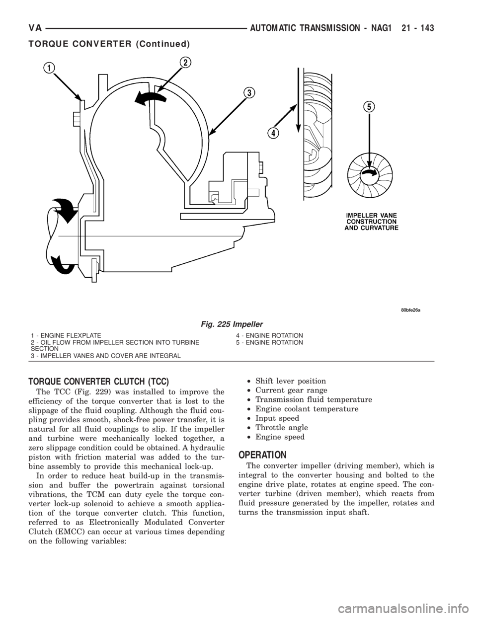
The converter impeller (driving member), which is
integral to the converter housing and bolted to the
engine drive plate, rotates at engine speed. The con-
verter turbine (driven member), which reacts from
fluid pressure generated by the impeller, rotates and
turns the transmission input shaft.
Fig. 225 Impeller
1 - ENGINE FLEXPLATE 4 - ENGINE ROTATION
2 - OIL FLOW FROM IMPELLER SECTION INTO TURBINE
SECTION5 - ENGINE ROTATION
3 - IMPELLER VANES AND COVER ARE INTEGRAL
VAAUTOMATIC TRANSMISSION - NAG1 21 - 143
TORQUE CONVERTER (Continued)