2005 MERCEDES-BENZ SPRINTER heater
[x] Cancel search: heaterPage 1163 of 1232
(9) Disconnect the wire harness connector from the
blower motor (Refer to 24 - HEATING & AIR CON-
DITIONING/DISTRIBUTION/BLOWER MOTOR -
REMOVAL).
(10) Remove the nuts and washers that secure the
ventilation housing to the body and remove the ven-
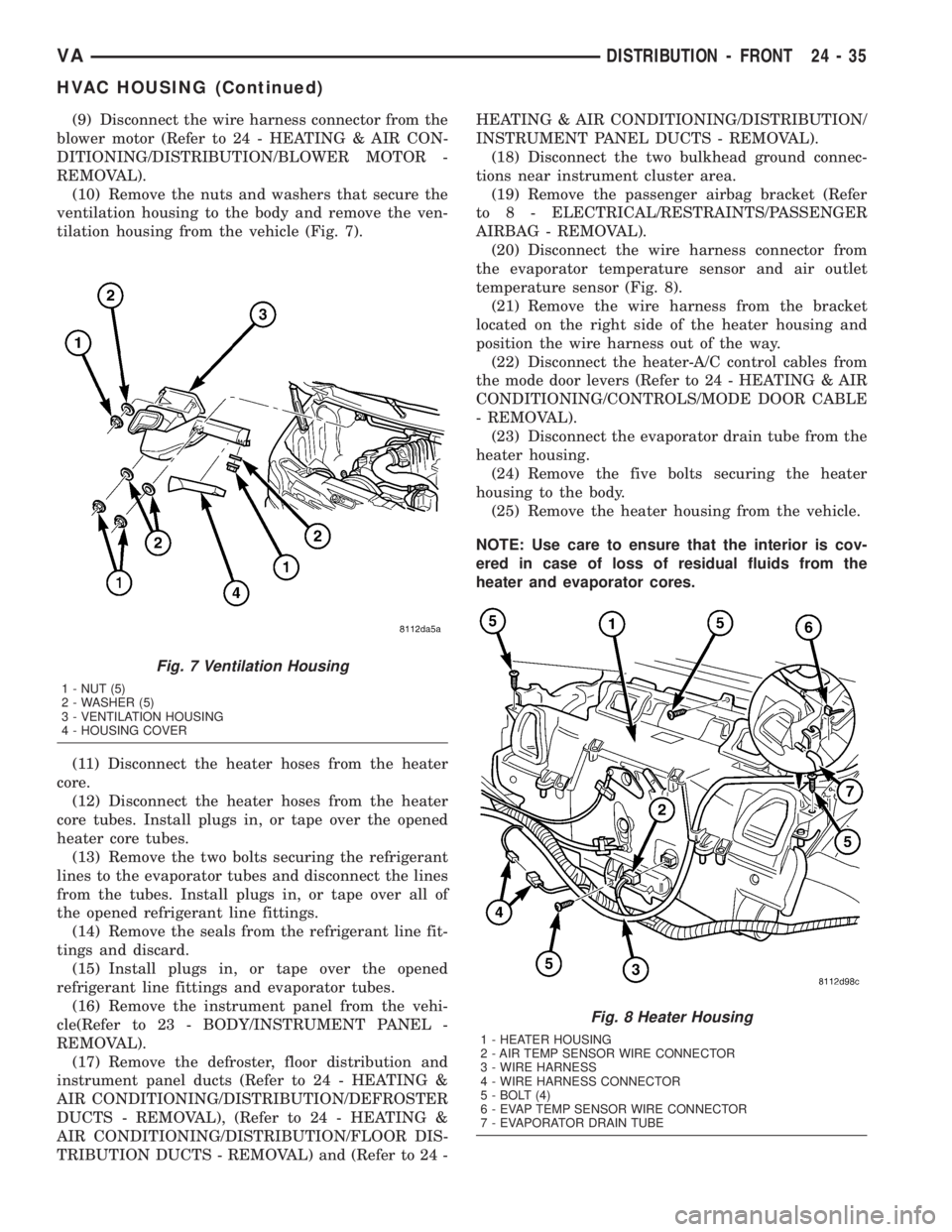
tilation housing from the vehicle (Fig. 7).
(11) Disconnect the heater hoses from the heater
core.
(12) Disconnect the heater hoses from the heater
core tubes. Install plugs in, or tape over the opened
heater core tubes.
(13) Remove the two bolts securing the refrigerant
lines to the evaporator tubes and disconnect the lines
from the tubes. Install plugs in, or tape over all of
the opened refrigerant line fittings.
(14) Remove the seals from the refrigerant line fit-
tings and discard.
(15) Install plugs in, or tape over the opened
refrigerant line fittings and evaporator tubes.
(16) Remove the instrument panel from the vehi-
cle(Refer to 23 - BODY/INSTRUMENT PANEL -
REMOVAL).
(17) Remove the defroster, floor distribution and
instrument panel ducts (Refer to 24 - HEATING &
AIR CONDITIONING/DISTRIBUTION/DEFROSTER
DUCTS - REMOVAL), (Refer to 24 - HEATING &
AIR CONDITIONING/DISTRIBUTION/FLOOR DIS-
TRIBUTION DUCTS - REMOVAL) and (Refer to 24 -HEATING & AIR CONDITIONING/DISTRIBUTION/
INSTRUMENT PANEL DUCTS - REMOVAL).
(18) Disconnect the two bulkhead ground connec-
tions near instrument cluster area.
(19) Remove the passenger airbag bracket (Refer
to 8 - ELECTRICAL/RESTRAINTS/PASSENGER
AIRBAG - REMOVAL).
(20) Disconnect the wire harness connector from
the evaporator temperature sensor and air outlet
temperature sensor (Fig. 8).
(21) Remove the wire harness from the bracket
located on the right side of the heater housing and
position the wire harness out of the way.
(22) Disconnect the heater-A/C control cables from
the mode door levers (Refer to 24 - HEATING & AIR
CONDITIONING/CONTROLS/MODE DOOR CABLE
- REMOVAL).
(23) Disconnect the evaporator drain tube from the
heater housing.
(24) Remove the five bolts securing the heater
housing to the body.
(25) Remove the heater housing from the vehicle.
NOTE: Use care to ensure that the interior is cov-
ered in case of loss of residual fluids from the
heater and evaporator cores.
Fig. 7 Ventilation Housing
1 - NUT (5)
2 - WASHER (5)
3 - VENTILATION HOUSING
4 - HOUSING COVER
Fig. 8 Heater Housing
1 - HEATER HOUSING
2 - AIR TEMP SENSOR WIRE CONNECTOR
3 - WIRE HARNESS
4 - WIRE HARNESS CONNECTOR
5 - BOLT (4)
6 - EVAP TEMP SENSOR WIRE CONNECTOR
7 - EVAPORATOR DRAIN TUBE
VADISTRIBUTION - FRONT 24 - 35
HVAC HOUSING (Continued)
Page 1164 of 1232
DISASSEMBLY
(1) Remove the heater and ventilation housings
from the vehicle (Refer to 24 - HEATING & AIR
CONDITIONING/DISTRIBUTION/HVAC HOUSING
- REMOVAL).
(2) Place the heater housing in the upright posi-
tion on a work bench, making allowance for leakage
of fluids.
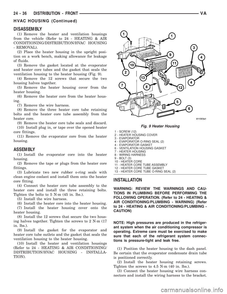
(3) Remove the gasket located at the evaporator
and heater core tubes and the gasket that seals the
ventilation housing to the heater housing (Fig. 9).
(4) Remove the 12 screws that secure the two
housing halves together.
(5) Remove the heater housing cover from the
heater housing.
(6) Remove the heater core from the heater hous-
ing.
(7) Remove the wire harness.
(8) Remove the three heater core tube retaining
bolts and the heater core tube assembly from the
heater core.
(9) Remove the heater core tube seals and discard.
(10) Install plug in, or tape over the opened heater
core fittings.
(11) Remove the evaporator core from the heater
housing.
ASSEMBLY
(1) Install the evaporator core into the heater
housing.
(2) Remove the tape or plugs from the heater core
fittings.
(3) Lubricate two new rubber o-ring seals with
clean engine coolant and install them onto the heater
core fitting.
(4) Connect the heater core tube assembly to the
heater core and install the three retaining bolts.
Tighten the bolts to 5 N´m (45 in. lbs.).
(5) Install the wire harness.
(6) Install the heater core into the heater housing.
(7) Install the heater housing cover onto the
heater housing.
(8) Install the 12 screws that secure the two hous-
ing halves together. Tighten the screws to 2 N´m (17
in. lbs.).
(9) Install the gasket for the evaporator and
heater core tube outlets and the gasket that seals the
ventilation housing to the heater housing.
(10) Install the heater and ventilation housings
(Refer to 24 - HEATING & AIR CONDITIONING/
DISTRIBUTION/HVAC HOUSING - INSTALLA-
TION).
INSTALLATION
WARNING: REVIEW THE WARNINGS AND CAU-
TIONS IN PLUMBING BEFORE PERFORMING THE
FOLLOWING OPERATION. (Refer to 24 - HEATING &
AIR CONDITIONING/PLUMBING - WARNING) (Refer
to 24 - HEATING & AIR CONDITIONING/PLUMBING -
CAUTION)
NOTE: High pressures are produced in the refriger-
ant system when the air conditioning compressor is
operating. Extreme care must be exercised to make
sure that each of the refrigerant system connec-
tions is pressure-tight and leak free.
(1) Position the heater housing to the dash panel.
Be certain that the evaporator condensate drain tube
is positioned correctly.
(2) Install the heater housing retaining screws.
Tighten the screws to 4.5 N´m (40 in. lbs.).
(3) Connect the heater housing wire harness con-
nectors and install the wiring harness to the bracket.
Fig. 9 Heater Housing
1 - SCREW (12)
2 - HEATER HOUSING COVER
3 - EVAPORATOR
4 - EVAPORATOR O-RING SEAL (2)
4 - EVAPORATOR GASKET
6 - VENTILATION HOUSING GASKET
7 - HEATER HOUSING
8 - WIRING HARNESS
9 - BOLT (3)
10 - HEATER CORE
11 - HEATER CORE TUBE ASSEMBLY
12 - HEATER CORE TUBE GASKET
13 - HEATER CORE TUBE O-RING SEAL (2)
24 - 36 DISTRIBUTION - FRONTVA
HVAC HOUSING (Continued)
Page 1165 of 1232
(4) Connect the heater-A/C control cables to the
mode door levers (Refer to 24 - HEATING & AIR
CONDITIONING/CONTROLS/MODE DOOR CABLE
- INSTALLATION).
(5) Reinstall the passenger airbag bracket (Refer
to 8 - ELECTRICAL/RESTRAINTS/PASSENGER
AIRBAG - INSTALLATION).
(6) Reconnect the two bulkhead ground connection
near the instrument cluster area.
(7) Reinstall the defroster, floor distribution and
instrument panel ducts.
(8) Reinstall the instrument panel (Refer to 23 -
BODY/INSTRUMENT PANEL/INSTRUMENT
PANEL ASSEMBLY - INSTALLATION).
(9) Unplug or remove the tape from the opened
refrigerant line fittings.
(10) Lubricate two new rubber o-ring seals with
clean refrigerant oil and install them onto the evap-
orator core fittings.
(11) Connect the refrigerant line terminal block to
the evaporator tubes.
(12) Install the two bolts that secure the refriger-
ant line terminal block to the evaporator. Tighten the
bolts to 5 N´m (45 in. lbs.).
(13) Unplug or remove the tape from the heater
core hoses and tubes.
(14) Connect the heater hoses to the heater core
tubes and install the heater hose clamps.
(15) Install the ventilation housing to the dash
panel.
(16) Install the nuts and washers that secure the
ventilation housing to the dash panel. Tighten the
nuts to 5 N´m (45 in. lbs.).
(17) Connect the wire harness connectors to the
blower motor, blower motor resistor block and the
recirculation door actuator.
(18) Connect the vacuum harness connector to the
recirculation door actuator.
(19) Install the air filter into the ventilation hous-
ing (Refer to 24 - HEATING & AIR CONDITION-
ING/DISTRIBUTION/AIR FILTER -
INSTALLATION).
(20) Install the windshield washer reservoir (Refer
to 8 - ELECTRICAL/WIPERS/WASHERS/WASHER
RESERVOIR - INSTALLATION).
(21) Install the air cleaner housing (Refer to 9 -
ENGINE/AIR INTAKE SYSTEM/AIR CLEANER
HOUSING - INSTALLATION).
(22) Reconnect the battery negative cable.
(23) Refill the engine cooling system (Refer to 7 -
COOLING/ENGINE/COOLANT - STANDARD PRO-
CEDURE).
(24) Evacuate the refrigerant system (Refer to 24 -
HEATING & AIR CONDITIONING/PLUMBING -
STANDARD PROCEDURE - REFRIGERANT SYS-
TEM EVACUATE).(25) Charge the refrigerant system (Refer to 24 -
HEATING & AIR CONDITIONING/PLUMBING -
STANDARD PROCEDURE - REFRIGERANT SYS-
TEM CHARGE).
(26) Start the engine and check for proper opera-
tion of the heating and air conditioning systems.
INSTRUMENT PANEL DUCTS
REMOVAL
(1) Remove the instrument panel (Refer to 23 -
BODY/INSTRUMENT PANEL/INSTRUMENT
PANEL ASSEMBLY - REMOVAL).
(2) Remove the defroster ducts (Refer to 24 -
HEATING & AIR CONDITIONING/DISTRIBUTION/
DEFROSTER DUCTS - REMOVAL).
(3) Remove the floor distribution ducts (Refer to 24
- HEATING & AIR CONDITIONING/DISTRIBU-
TION/FLOOR DISTRIBUTION DUCTS - REMOV-
AL).
(4) If removing the right instrument panel duct,
remove the passenger air bag module and bracket
(Refer to 8 - ELECTRICAL/RESTRAINTS/PASSEN-
GER AIRBAG - REMOVAL).
(5) Remove the screws that secure the left and/or
right instrument panel duct and remove the duct(s)
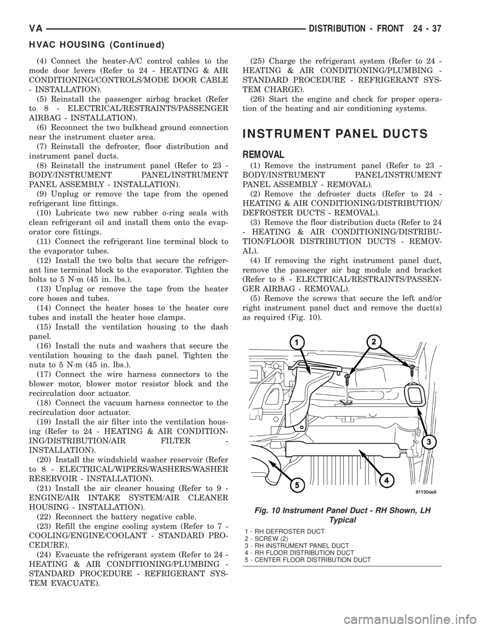
as required (Fig. 10).
Fig. 10 Instrument Panel Duct - RH Shown, LH
Typical
1 - RH DEFROSTER DUCT
2 - SCREW (2)
3 - RH INSTRUMENT PANEL DUCT
4 - RH FLOOR DISTRIBUTION DUCT
5 - CENTER FLOOR DISTRIBUTION DUCT
VADISTRIBUTION - FRONT 24 - 37
HVAC HOUSING (Continued)
Page 1166 of 1232

INSTALLATION
(1) Connect the instrument panel duct(s) to the
heater housing as required.
(2) Install the instrument panel duct retaining
screws. Tighten the screws to 2 N´m (17 in. lbs.).
(3) If servicing the right instrument panel duct,
install the passenger air bag module and bracket
(Refer to 8 - ELECTRICAL/RESTRAINTS/PASSEN-
GER AIRBAG - INSTALLATION).(4) Install the floor distribution ducts (Refer to 24
- HEATING & AIR CONDITIONING/DISTRIBU-
TION/FLOOR DISTRIBUTION DUCTS - INSTAL-
LATION).
(5) Install the defroster ducts (Refer to 24 - HEAT-
ING & AIR CONDITIONING/DISTRIBUTION/DE-
FROSTER DUCTS - INSTALLATION).
(6) Install the instrument panel (Refer to 23 -
BODY/INSTRUMENT PANEL/INSTRUMENT
PANEL ASSEMBLY - INSTALLATION).
24 - 38 DISTRIBUTION - FRONTVA
INSTRUMENT PANEL DUCTS (Continued)
Page 1171 of 1232
PLUMBING
TABLE OF CONTENTS
page page
PLUMBING
DESCRIPTION - REFRIGERANT LINE.......44
OPERATION - REFRIGERANT LINE.........44
WARNING.............................44
CAUTION
CAUTION...........................45
REFRIGERANT HOSES/LINES/TUBES
PRECAUTIONS.......................45
DIAGNOSIS AND TESTING - REFRIGERANT
SYSTEM LEAKS......................46
STANDARD PROCEDURE
STANDARD PROCEDURE - REFRIGERANT
SYSTEM SERVICE EQUIPMENT..........46
STANDARD PROCEDURE - REFRIGERANT
RECOVERY..........................47
STANDARD PROCEDURE - REFRIGERANT
SYSTEM EVACUATE...................47
STANDARD PROCEDURE - REFRIGERANT
SYSTEM CHARGE.....................48
SPECIFICATIONS
CHARGE CAPACITY...................49
A/C COMPRESSOR
DESCRIPTION.........................49
OPERATION...........................49
DIAGNOSIS AND TESTING - COMPRESSOR
NOISE..............................49
REMOVAL.............................50
INSTALLATION.........................51
A/C CONDENSER
DESCRIPTION.........................52
OPERATION...........................52
REMOVAL.............................52
INSTALLATION.........................52
A/C DISCHARGE LINE
REMOVAL.............................53
INSTALLATION.........................54
A/C EVAPORATOR
DESCRIPTION.........................54
OPERATION...........................54
REMOVAL.............................55
INSTALLATION.........................55
A/C EXPANSION VALVE
DESCRIPTION.........................55
OPERATION...........................55
DIAGNOSIS AND TESTING - A/C EXPANSION
VALVE ..............................56REMOVAL.............................56
INSTALLATION.........................56
ELECTRIC COOLANT PUMP
DESCRIPTION.........................57
OPERATION...........................57
REMOVAL.............................57
INSTALLATION.........................57
HEATER CORE
DESCRIPTION.........................57
OPERATION...........................57
REMOVAL.............................58
INSTALLATION.........................58
LIQUID LINE
REMOVAL.............................58
INSTALLATION.........................59
REAR EVAPORATOR
REMOVAL.............................60
INSTALLATION.........................61
REAR EXPANSION VALVE
REMOVAL.............................62
INSTALLATION.........................63
RECEIVER/DRIER
DESCRIPTION.........................64
OPERATION...........................64
REMOVAL.............................64
INSTALLATION.........................64
REFRIGERANT
DESCRIPTION.........................65
OPERATION...........................65
REFRIGERANT OIL
DESCRIPTION.........................65
OPERATION...........................65
STANDARD PROCEDURE - REFRIGERANT
OIL LEVEL...........................65
SUCTION LINE
REMOVAL.............................66
INSTALLATION.........................66
WAT E R VA LV E
REMOVAL.............................67
INSTALLATION.........................67
UNDERBODY LINES
REMOVAL.............................68
INSTALLATION.........................69
VAPLUMBING 24 - 43
Page 1176 of 1232
(2) Open the low and high side valves and start
the charging station vacuum pump. When the suc-
tion gauge reads 88 kPa (26 in. Hg.) vacuum or
greater, close all of the valves and turn off the vac-
uum pump.
(a) If the refrigerant system fails to reach the
specified vacuum, the system has a leak that must
be corrected. (Refer to 24 - HEATING & AIR CON-
DITIONING/PLUMBING - DIAGNOSIS AND
TESTING - REFRIGERANT SYSTEM LEAKS)
(b) If the refrigerant system maintains the spec-
ified vacuum for five minutes, restart the vacuum
pump, open the suction and discharge valves and
evacuate the system for an additional ten minutes.
(3) Close all of the valves, and turn off the charg-
ing station vacuum pump.
(4) The refrigerant system is now ready to be
charged with R-134a refrigerant. (Refer to 24 -
HEATING & AIR CONDITIONING/PLUMBING -
STANDARD PROCEDURE - REFRIGERANT SYS-
TEM CHARGE)
STANDARD PROCEDURE - REFRIGERANT
SYSTEM CHARGE
WARNING: REVIEW THE WARNINGS AND CAU-
TIONS IN THE FRONT OF THIS SECTION BEFORE
PERFORMING THE FOLLOWING OPERATION.
(Refer to 24 - HEATING & AIR CONDITIONING/
PLUMBING - WARNING) (Refer to 24 - HEATING &
AIR CONDITIONING/PLUMBING - CAUTION)
CAUTION: A small amount of refrigerant oil is
removed from the A/C system each time the refrig-
erant system is recovered and evacuated. Before
charging the A/C system, you MUST replenish any
oil lost during the recovery process. Refer the
equipment manufacturer instructions for more infor-
mation.
After the refrigerant system has been tested for
leaks and evacuated, a refrigerant charge can be
injected into the system. (Refer to 24 - HEATING &
AIR CONDITIONING/PLUMBING - SPECIFICA-
TIONS - CHARGE CAPACITY)
A R-134a refrigerant recovery/recycling/charging
station that meets SAE Standard J2210 must be
used to charge the refrigerant system with R-134a
refrigerant. Refer to the operating instructions sup-
plied by the equipment manufacturer for proper care
and use of this equipment.
PARTIAL CHARGE METHOD
WARNING: REVIEW THE WARNINGS AND CAU-
TIONS IN THE FRONT OF THIS SECTION BEFORE
PERFORMING THE FOLLOWING OPERATION.
(Refer to 24 - HEATING & AIR CONDITIONING/
PLUMBING - WARNING) (Refer to 24 - HEATING &
AIR CONDITIONING/PLUMBING - CAUTION)
The partial charge method is used to add a partial
charge to a refrigerant system that is low on refrig-
erant. To perform this procedure the evaporator inlet
and outlet tube temperatures are measured. The
temperature difference is measured with a tempera-
ture meter with one or two clamp-on thermocouple
probes. The difference between the evaporator inlet
and outlet tube temperatures will determine the
amount of refrigerant needed.
Before adding a partial refrigerant charge, check
for refrigerant system leaks. (Refer to 24 - HEATING
& AIR CONDITIONING/PLUMBING - DIAGNOSIS
AND TESTING - REFRIGERANT SYSTEM LEAKS)
If a leak is found, make the necessary repairs before
attempting a full or partial refrigerant charge.
(1) Attach a manifold gauge set to the refrigerant
system service ports.
(2) Attach the two clamp-on thermocouple probes
to the inlet and outlet tubes of the evaporator coil.
²If a single thermocouple probe is used, attach
the probe to the evaporator inlet tube just before the
collar of the refrigerant line connector fitting. The
probe must make contact with the bottom surface of
the evaporator inlet tube.
²If dual thermocouple probes are used, attach
probe 1 to the evaporator inlet tube, and probe 2 to
the evaporator outlet tube. Attach both probes to the
evaporator tubes just before the collar of the refrig-
erant line connector fittings. The probes must make
contact with the bottom surfaces of the evaporator
inlet and outlet tubes.
(3) Open all of the windows or doors of the passen-
ger compartment.
(4) Set the A/C button on the A/C Heater controls
to the on position, the temperature control knob in
the full cool position, select Recirculation Mode, and
place the blower motor switch in the highest speed
position.
(5) Start the engine and hold the engine idle speed
at 1,000 rpm. Allow the engine to warm up to normal
operating temperature.
(6) The compressor clutch may cycle, depending
upon ambient temperature, humidity, and the refrig-
erant system charge level.
(7) Hold the engine idle speed at 1,000 rpm.
(8) Allow three to five minutes for the refrigerant
system to stabilize, then record the temperatures of
the evaporator inlet and outlet tubes.
24 - 48 PLUMBINGVA
PLUMBING (Continued)
Page 1182 of 1232
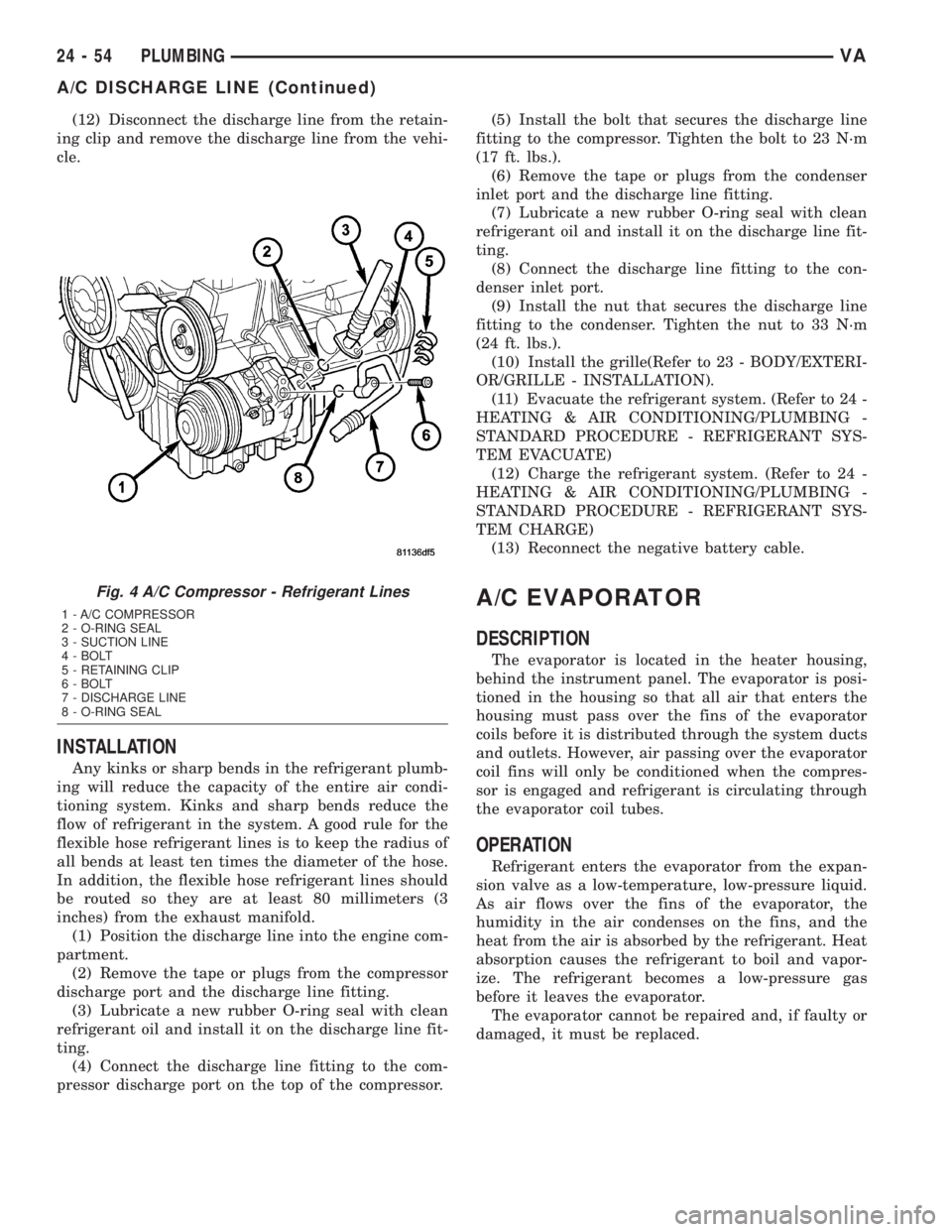
(12) Disconnect the discharge line from the retain-
ing clip and remove the discharge line from the vehi-
cle.
INSTALLATION
Any kinks or sharp bends in the refrigerant plumb-
ing will reduce the capacity of the entire air condi-
tioning system. Kinks and sharp bends reduce the
flow of refrigerant in the system. A good rule for the
flexible hose refrigerant lines is to keep the radius of
all bends at least ten times the diameter of the hose.
In addition, the flexible hose refrigerant lines should
be routed so they are at least 80 millimeters (3
inches) from the exhaust manifold.
(1) Position the discharge line into the engine com-
partment.
(2) Remove the tape or plugs from the compressor
discharge port and the discharge line fitting.
(3) Lubricate a new rubber O-ring seal with clean
refrigerant oil and install it on the discharge line fit-
ting.
(4) Connect the discharge line fitting to the com-
pressor discharge port on the top of the compressor.(5) Install the bolt that secures the discharge line
fitting to the compressor. Tighten the bolt to 23 N´m
(17 ft. lbs.).
(6) Remove the tape or plugs from the condenser
inlet port and the discharge line fitting.
(7) Lubricate a new rubber O-ring seal with clean
refrigerant oil and install it on the discharge line fit-
ting.
(8) Connect the discharge line fitting to the con-
denser inlet port.
(9) Install the nut that secures the discharge line
fitting to the condenser. Tighten the nut to 33 N´m
(24 ft. lbs.).
(10) Install the grille(Refer to 23 - BODY/EXTERI-
OR/GRILLE - INSTALLATION).
(11) Evacuate the refrigerant system. (Refer to 24 -
HEATING & AIR CONDITIONING/PLUMBING -
STANDARD PROCEDURE - REFRIGERANT SYS-
TEM EVACUATE)
(12) Charge the refrigerant system. (Refer to 24 -
HEATING & AIR CONDITIONING/PLUMBING -
STANDARD PROCEDURE - REFRIGERANT SYS-
TEM CHARGE)
(13) Reconnect the negative battery cable.
A/C EVAPORATOR
DESCRIPTION
The evaporator is located in the heater housing,
behind the instrument panel. The evaporator is posi-
tioned in the housing so that all air that enters the
housing must pass over the fins of the evaporator
coils before it is distributed through the system ducts
and outlets. However, air passing over the evaporator
coil fins will only be conditioned when the compres-
sor is engaged and refrigerant is circulating through
the evaporator coil tubes.
OPERATION
Refrigerant enters the evaporator from the expan-
sion valve as a low-temperature, low-pressure liquid.
As air flows over the fins of the evaporator, the
humidity in the air condenses on the fins, and the
heat from the air is absorbed by the refrigerant. Heat
absorption causes the refrigerant to boil and vapor-
ize. The refrigerant becomes a low-pressure gas
before it leaves the evaporator.
The evaporator cannot be repaired and, if faulty or
damaged, it must be replaced.
Fig. 4 A/C Compressor - Refrigerant Lines
1 - A/C COMPRESSOR
2 - O-RING SEAL
3 - SUCTION LINE
4 - BOLT
5 - RETAINING CLIP
6 - BOLT
7 - DISCHARGE LINE
8 - O-RING SEAL
24 - 54 PLUMBINGVA
A/C DISCHARGE LINE (Continued)
Page 1183 of 1232
REMOVAL
WARNING: ON VEHICLES EQUIPPED WITH AIR-
BAGS, DISABLE THE AIRBAG SYSTEM BEFORE
ATTEMPTING ANY STEERING WHEEL, STEERING
COLUMN, OR INSTRUMENT PANEL COMPONENT
DIAGNOSIS OR SERVICE. DISCONNECT AND ISO-
LATE THE BATTERY NEGATIVE (GROUND) CABLE,
THEN WAIT TWO MINUTES FOR THE AIRBAG SYS-
TEM CAPACITOR TO DISCHARGE BEFORE PER-
FORMING FURTHER DIAGNOSIS OR SERVICE. THIS
IS THE ONLY SURE WAY TO DISABLE THE AIRBAG
SYSTEM. FAILURE TO TAKE THE PROPER PRE-
CAUTIONS COULD RESULT IN AN ACCIDENTAL
AIRBAG DEPLOYMENT AND POSSIBLE PERSONAL
INJURY.
WARNING: REVIEW THE WARNINGS AND CAU-
TIONS IN THE FRONT OF THIS SECTION BEFORE
PERFORMING THE FOLLOWING OPERATION (Refer
to 24 - HEATING & AIR CONDITIONING/PLUMBING -
WARNING) and (Refer to 24 - HEATING & AIR CON-
DITIONING/PLUMBING - CAUTION).
(1) Remove the heater housing (Refer to 24 -
HEATING & AIR CONDITIONING/DISTRIBUTION/
HVAC HOUSING - REMOVAL).
(2) Disassemble the heater housing to access the
evaporator (Refer to 24 - HEATING & AIR CONDI-
TIONING/DISTRIBUTION/HVAC HOUSING - DIS-
ASSEMBLY).
(3) Lift the evaporator out of the lower half of the
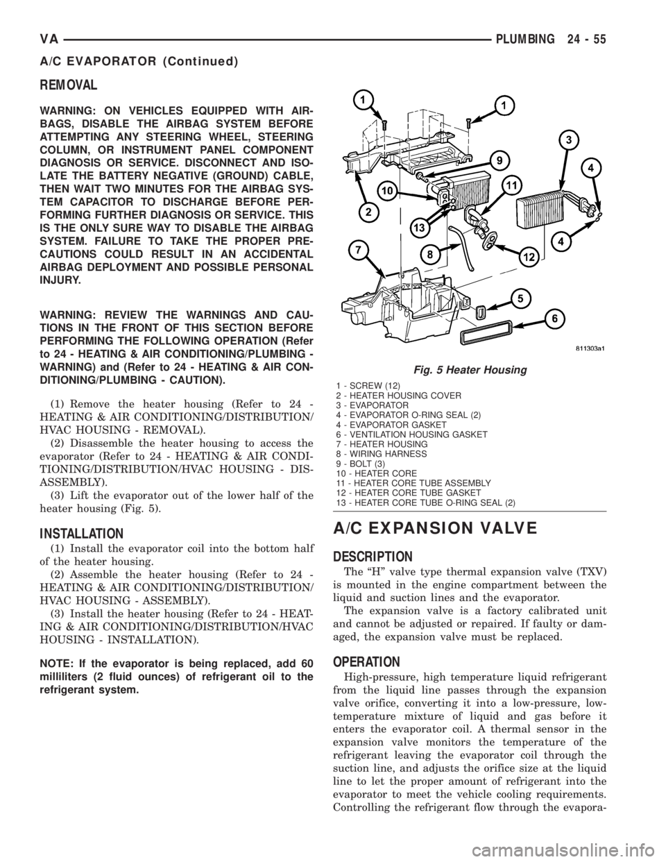
heater housing (Fig. 5).
INSTALLATION
(1) Install the evaporator coil into the bottom half
of the heater housing.
(2) Assemble the heater housing (Refer to 24 -
HEATING & AIR CONDITIONING/DISTRIBUTION/
HVAC HOUSING - ASSEMBLY).
(3) Install the heater housing (Refer to 24 - HEAT-
ING & AIR CONDITIONING/DISTRIBUTION/HVAC
HOUSING - INSTALLATION).
NOTE: If the evaporator is being replaced, add 60
milliliters (2 fluid ounces) of refrigerant oil to the
refrigerant system.
A/C EXPANSION VALVE
DESCRIPTION
The ªHº valve type thermal expansion valve (TXV)
is mounted in the engine compartment between the
liquid and suction lines and the evaporator.
The expansion valve is a factory calibrated unit
and cannot be adjusted or repaired. If faulty or dam-
aged, the expansion valve must be replaced.
OPERATION
High-pressure, high temperature liquid refrigerant
from the liquid line passes through the expansion
valve orifice, converting it into a low-pressure, low-
temperature mixture of liquid and gas before it
enters the evaporator coil. A thermal sensor in the
expansion valve monitors the temperature of the
refrigerant leaving the evaporator coil through the
suction line, and adjusts the orifice size at the liquid
line to let the proper amount of refrigerant into the
evaporator to meet the vehicle cooling requirements.
Controlling the refrigerant flow through the evapora-
Fig. 5 Heater Housing
1 - SCREW (12)
2 - HEATER HOUSING COVER
3 - EVAPORATOR
4 - EVAPORATOR O-RING SEAL (2)
4 - EVAPORATOR GASKET
6 - VENTILATION HOUSING GASKET
7 - HEATER HOUSING
8 - WIRING HARNESS
9 - BOLT (3)
10 - HEATER CORE
11 - HEATER CORE TUBE ASSEMBLY
12 - HEATER CORE TUBE GASKET
13 - HEATER CORE TUBE O-RING SEAL (2)
VAPLUMBING 24 - 55
A/C EVAPORATOR (Continued)