2005 MERCEDES-BENZ SPRINTER heater
[x] Cancel search: heaterPage 705 of 1232
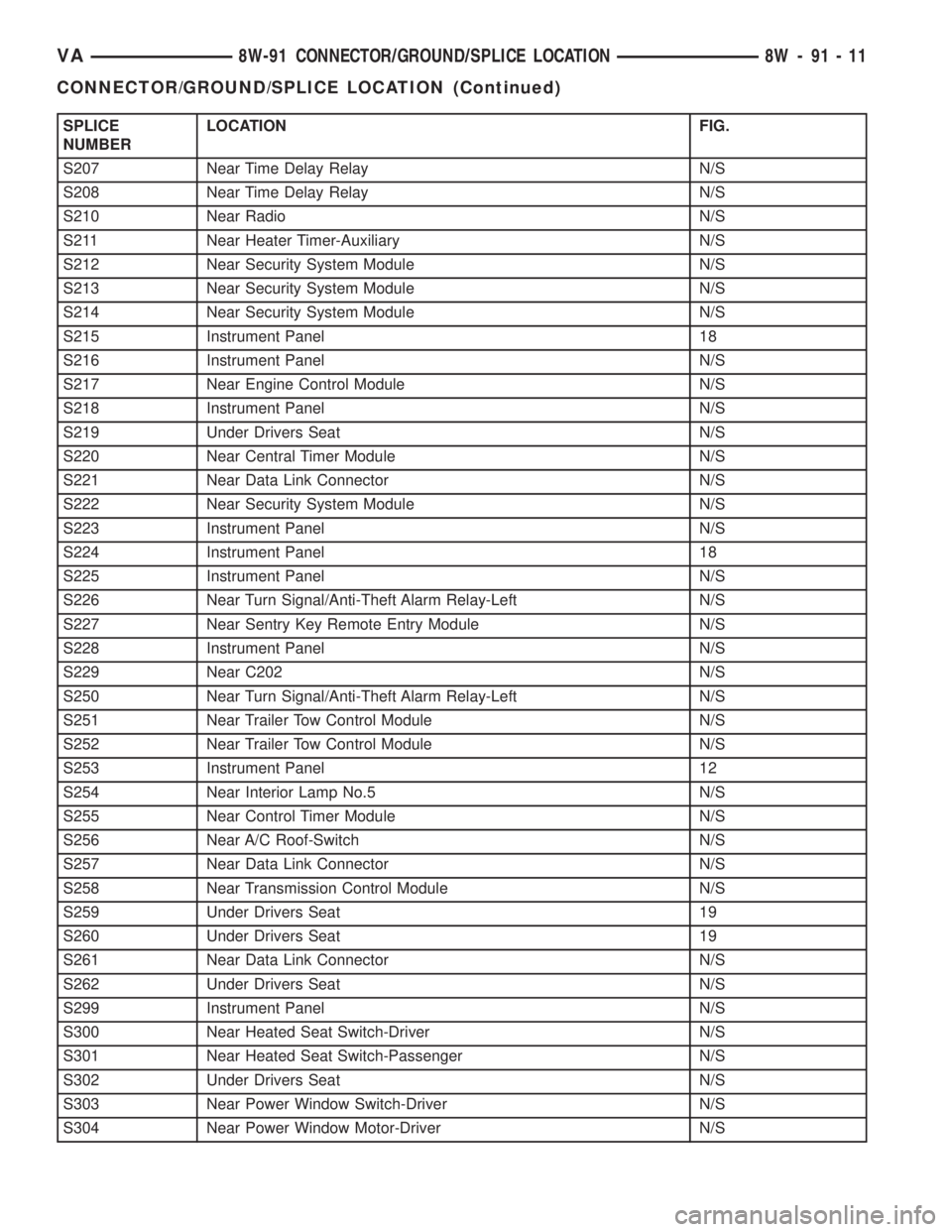
SPLICE
NUMBERLOCATION FIG.
S207 Near Time Delay Relay N/S
S208 Near Time Delay Relay N/S
S210 Near Radio N/S
S211 Near Heater Timer-Auxiliary N/S
S212 Near Security System Module N/S
S213 Near Security System Module N/S
S214 Near Security System Module N/S
S215 Instrument Panel 18
S216 Instrument Panel N/S
S217 Near Engine Control Module N/S
S218 Instrument Panel N/S
S219 Under Drivers Seat N/S
S220 Near Central Timer Module N/S
S221 Near Data Link Connector N/S
S222 Near Security System Module N/S
S223 Instrument Panel N/S
S224 Instrument Panel 18
S225 Instrument Panel N/S
S226 Near Turn Signal/Anti-Theft Alarm Relay-Left N/S
S227 Near Sentry Key Remote Entry Module N/S
S228 Instrument Panel N/S
S229 Near C202 N/S
S250 Near Turn Signal/Anti-Theft Alarm Relay-Left N/S
S251 Near Trailer Tow Control Module N/S
S252 Near Trailer Tow Control Module N/S
S253 Instrument Panel 12
S254 Near Interior Lamp No.5 N/S
S255 Near Control Timer Module N/S
S256 Near A/C Roof-Switch N/S
S257 Near Data Link Connector N/S
S258 Near Transmission Control Module N/S
S259 Under Drivers Seat 19
S260 Under Drivers Seat 19
S261 Near Data Link Connector N/S
S262 Under Drivers Seat N/S
S299 Instrument Panel N/S
S300 Near Heated Seat Switch-Driver N/S
S301 Near Heated Seat Switch-Passenger N/S
S302 Under Drivers Seat N/S
S303 Near Power Window Switch-Driver N/S
S304 Near Power Window Motor-Driver N/S
VA8W-91 CONNECTOR/GROUND/SPLICE LOCATION 8W - 91 - 11
CONNECTOR/GROUND/SPLICE LOCATION (Continued)
Page 744 of 1232
(15) Disconnect the coolant hose of the heater sup-
ply at the coolant pipe at the side of the cylinder
head (Fig. 3).
(16) Disconnect the vacuum hose at the turbo-
charger (Fig. 3).
(17) Disconnect the air inlet hose at the turbo-
charger (Fig. 3).
(18) Raise and support the vehicle.
(19) Disconnect the front exhaust at the turbo-
charger.
(20) Disconnect the electrical connector at the
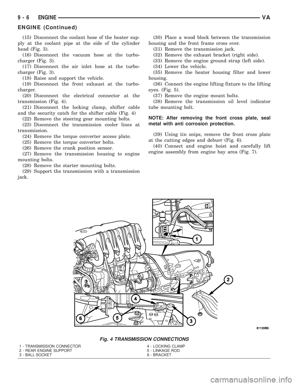
transmission (Fig. 4).
(21) Disconnect the locking clamp, shifter cable
and the security catch for the shifter cable (Fig. 4)
(22) Remove the steering gear mounting bolts.
(23) Disconnect the transmission cooler lines at
transmission.
(24) Remove the torque converter access plate.
(25) Remove the torque converter bolts.
(26) Remove the crank position sensor.
(27) Remove the transmission housing to engine
mounting bolts.
(28) Remove the starter mounting bolts.
(29) Support the transmission with a transmission
jack.(30) Place a wood block between the transmission
housing and the front frame cross over.
(31) Remove the transmission jack.
(32) Remove the exhaust bracket (right side).
(33) Remove the engine ground strap (left side).
(34) Lower the vehicle.
(35) Remove the heater housing filter and lower
housing.
(36) Connect the engine lifting fixture to the lifting
eyes. (Fig. 5).
(37) Remove the engine mount bolts.
(38) Remove the transmission oil level indicator
tube mounting bolt.
NOTE: After removing the front cross plate, seal
metal with anti corrosion protection.
(39) Using tin snips, remove the front cross plate
at the cutting edges and deburr (Fig. 6).
(40) Connect and engine hoist and carefully lift
engine assembly from engine bay area (Fig. 7).
Fig. 4 TRANSMISSION CONNECTIONS
1 - TRANSMISSION CONNECTOR 4 - LOCKING CLAMP
2 - REAR ENGINE SUPPORT 5 - LINKAGE ROD
3 - BALL SOCKET 6 - BRACKET
9 - 6 ENGINEVA
ENGINE (Continued)
Page 749 of 1232
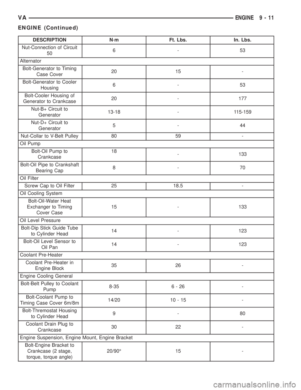
DESCRIPTION N´m Ft. Lbs. In. Lbs.
Nut-Connection of Circuit
506-53
Alternator
Bolt-Generator to Timing
Case Cover20 15 -
Bolt-Generator to Cooler
Housing6-53
Bolt-Cooler Housing of
Generator to Crankcase20 - 177
Nut-B+ Circuit to
Generator13-18 - 115-159
Nut-D+ Circuit to
Generator5-44
Nut-Collar to V-Belt Pulley 80 59 -
Oil Pump
Bolt-Oil Pump to
Crankcase18
- 133
Bolt-Oil Pipe to Crankshaft
Bearing Cap8-70
Oil Filter
Screw Cap to Oil Filter 25 18.5 -
Oil Cooling System
Bolt-Oil-Water Heat
Exchanger to Timing
Cover Case15 - 133
Oil Level Pressure
Bolt-Dip Stick Guide Tube
to Cylinder Head14 - 123
Bolt-Oil Level Sensor to
Oil Pan14 - 123
Coolant Pre-Heater
Coolant Pre-Heater in
Engine Block35 26 -
Engine Cooling General
Bolt-Belt Pulley to Coolant
Pump8-35 6 - 26 -
Bolt-Coolant Pump to
Timing Case Cover 6m/8m14/20 10 - 15 -
Bolt-Thremostat Housing
to Cylinder Head9-80
Coolant Drain Plug to
Crankcase30 22 -
Engine Suspension, Engine Mount, Engine Bracket
Bolt-Engine Bracket to
Crankcase (2 stage,
torque, torque angle)20/90É 15 -
VAENGINE 9 - 11
ENGINE (Continued)
Page 752 of 1232
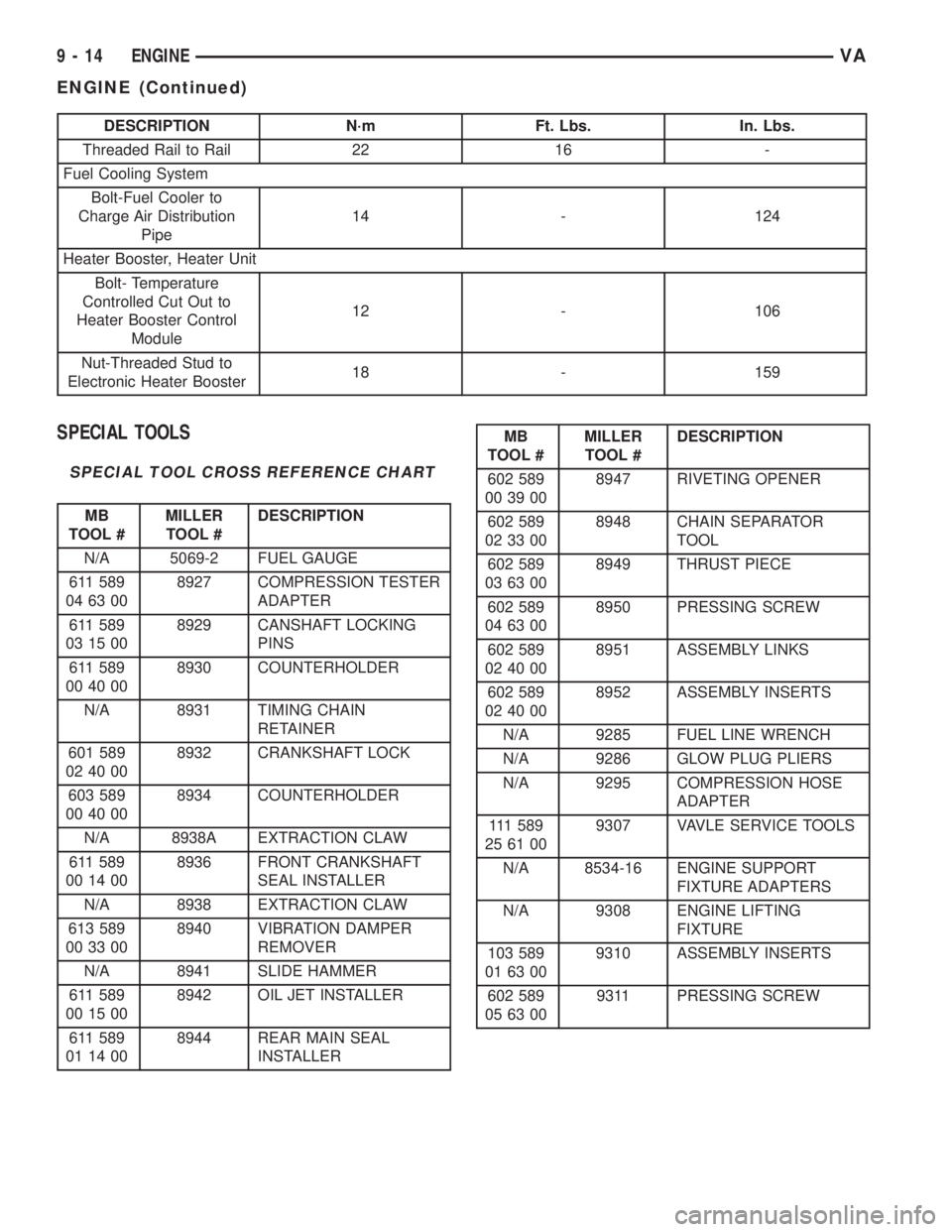
DESCRIPTION N´m Ft. Lbs. In. Lbs.
Threaded Rail to Rail 22 16 -
Fuel Cooling System
Bolt-Fuel Cooler to
Charge Air Distribution
Pipe14 - 124
Heater Booster, Heater Unit
Bolt- Temperature
Controlled Cut Out to
Heater Booster Control
Module12 - 106
Nut-Threaded Stud to
Electronic Heater Booster18 - 159
SPECIAL TOOLS
SPECIAL TOOL CROSS REFERENCE CHART
MB
TOOL #MILLER
TOOL #DESCRIPTION
N/A 5069-2 FUEL GAUGE
611 589
04 63 008927 COMPRESSION TESTER
ADAPTER
611 589
03 15 008929 CANSHAFT LOCKING
PINS
611 589
00 40 008930 COUNTERHOLDER
N/A 8931 TIMING CHAIN
RETAINER
601 589
02 40 008932 CRANKSHAFT LOCK
603 589
00 40 008934 COUNTERHOLDER
N/A 8938A EXTRACTION CLAW
611 589
00 14 008936 FRONT CRANKSHAFT
SEAL INSTALLER
N/A 8938 EXTRACTION CLAW
613 589
00 33 008940 VIBRATION DAMPER
REMOVER
N/A 8941 SLIDE HAMMER
611 589
00 15 008942 OIL JET INSTALLER
611 589
01 14 008944 REAR MAIN SEAL
INSTALLER
MB
TOOL #MILLER
TOOL #DESCRIPTION
602 589
00 39 008947 RIVETING OPENER
602 589
02 33 008948 CHAIN SEPARATOR
TOOL
602 589
03 63 008949 THRUST PIECE
602 589
04 63 008950 PRESSING SCREW
602 589
02 40 008951 ASSEMBLY LINKS
602 589
02 40 008952 ASSEMBLY INSERTS
N/A 9285 FUEL LINE WRENCH
N/A 9286 GLOW PLUG PLIERS
N/A 9295 COMPRESSION HOSE
ADAPTER
111 5 8 9
25 61 009307 VAVLE SERVICE TOOLS
N/A 8534-16 ENGINE SUPPORT
FIXTURE ADAPTERS
N/A 9308 ENGINE LIFTING
FIXTURE
103 589
01 63 009310 ASSEMBLY INSERTS
602 589
05 63 009311 PRESSING SCREW
9 - 14 ENGINEVA
ENGINE (Continued)
Page 786 of 1232
NOTE: If grooves can be felt in the belt pulley/vibra-
tion damper during inspection, the pulley/damper
must be replaced.
(6) Inspect hub at belt pulley/vibration damper for
wear grooves.
(7) Replace front crankshaft seal.
INSTALLATION
NOTE: Align parallel key, fix in place with grease.
Turn to ensure the slot is aligned with parallel key
in crankshaft.
NOTE: Front crankshaft seal must be replaced
before installing the belt pulley/vibration damper.
(1) Position the belt pulley/vibration damper.
(2) Install crankshaft center bolt and washer.
Tighten bolt in two stages. M8.8 bolt to 200N´m (148
lbs. ft.) then 90É, M10.9 bolt to 325N´m (240 lbs. ft.)
then 90É.
(3) Remove the retaining lock for the crankshaft/
ring gear (Fig. 43).
NOTE: Inspect accessory drive belt for wear.
Replace as necessary.
(4) Install accessory drive belt (Refer to 7 - COOL-
ING/ACCESSORY DRIVE/DRIVE BELTS - INSTAL-
LATION).
(5) Reconnect negative battery cable.
WARNING: USE EXTREME CAUTION WHEN THE
ENGINE IS IN OPERATION. DO NOT STAND IN A
DIRECT LINE WITH THE FAN. DO NOT PUT YOUR
HANDS NEAR THE PULLEYS, BELTS OR FAN. DO
NOT WEAR LOOSE CLOTHING.
(6) Start vehicle and inspect for leaks.
VACUUM PUMP
DESCRIPTION
The vacuum pump is operated by a slotted exten-
sion attached to the vacuum pump shaft. The vac-
uum pump shaft slotted extension fits into, and is
driven by, the exhaust camshaft gear.
The vacuum pump is a constant displacement,
vane-type pump. Vacuum is generated by vanes
mounted in the pump rotor. The rotor is located in
the pump housing and is pressed onto the pump
shaft.
The vacuum pump rotating components are inter-
nally lubricated.The vacuum pump is not serviceable and must be
replaced as a unit. Do not disassemble or attempt to
repair the pump.
OPERATION
Vacuum pump output is transmitted to the Heater,
Electronic, Vacuum, Air Conditioner (HEVAC) and
speed control, systems through a supply hose. The
hose is connected to an outlet port on the pump hous-
ing and uses an in-line check valve to retain system
vacuum when vehicle is not running.
Pump output ranges from a minimum of 8.5 to 25
inches vacuum.
The pump rotor and vanes are rotated by the pump
drive gear. The drive gear is operated by the exhaust
camshaft gear.
REMOVAL
(1) Disconnect negative battery cable.
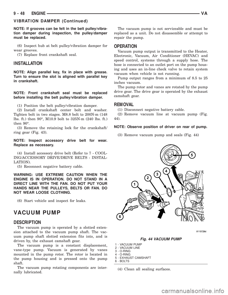
(2) Remove vacuum line at vacuum pump (Fig.
44).
NOTE: Observe position of driver on rear of pump.
(3) Remove vacuum pump and seals (Fig. 44)
(4) Clean all sealing surfaces.
Fig. 44 VACUUM PUMP
1 - VACUUM PUMP
2 - VACUUM LINE
3 - O-RING
4 - O-RING
5 - EXHAUST CAMSHAFT
6 - BOLTS
9 - 48 ENGINEVA
VIBRATION DAMPER (Continued)
Page 796 of 1232
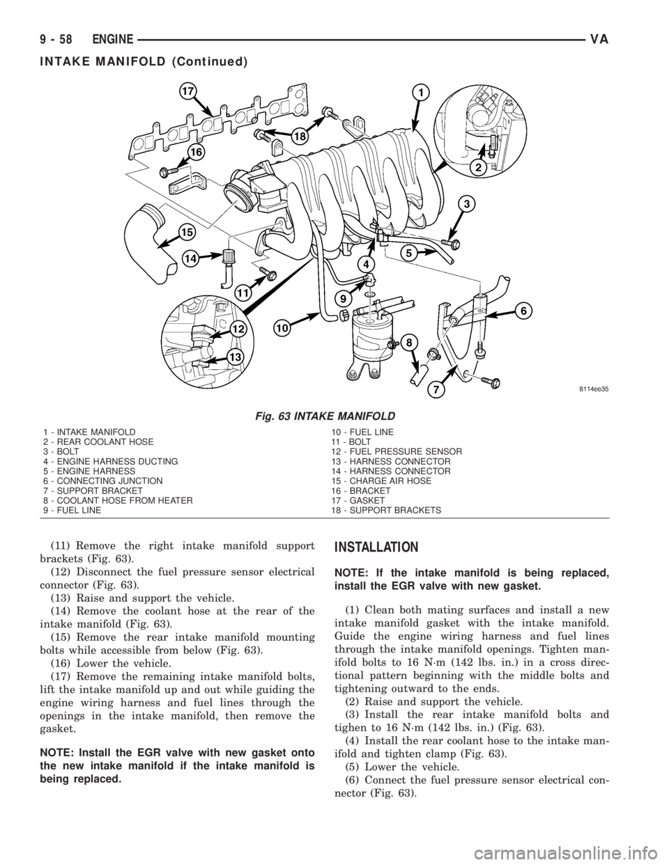
(11) Remove the right intake manifold support
brackets (Fig. 63).
(12) Disconnect the fuel pressure sensor electrical
connector (Fig. 63).
(13) Raise and support the vehicle.
(14) Remove the coolant hose at the rear of the
intake manifold (Fig. 63).
(15) Remove the rear intake manifold mounting
bolts while accessible from below (Fig. 63).
(16) Lower the vehicle.
(17) Remove the remaining intake manifold bolts,
lift the intake manifold up and out while guiding the
engine wiring harness and fuel lines through the
openings in the intake manifold, then remove the
gasket.
NOTE: Install the EGR valve with new gasket onto
the new intake manifold if the intake manifold is
being replaced.INSTALLATION
NOTE: If the intake manifold is being replaced,
install the EGR valve with new gasket.
(1) Clean both mating surfaces and install a new
intake manifold gasket with the intake manifold.
Guide the engine wiring harness and fuel lines
through the intake manifold openings. Tighten man-
ifold bolts to 16 N´m (142 lbs. in.) in a cross direc-
tional pattern beginning with the middle bolts and
tightening outward to the ends.
(2) Raise and support the vehicle.
(3) Install the rear intake manifold bolts and
tighen to 16 N´m (142 lbs. in.) (Fig. 63).
(4) Install the rear coolant hose to the intake man-
ifold and tighten clamp (Fig. 63).
(5) Lower the vehicle.
(6) Connect the fuel pressure sensor electrical con-
nector (Fig. 63).
Fig. 63 INTAKE MANIFOLD
1 - INTAKE MANIFOLD 10 - FUEL LINE
2 - REAR COOLANT HOSE 11 - BOLT
3 - BOLT 12 - FUEL PRESSURE SENSOR
4 - ENGINE HARNESS DUCTING 13 - HARNESS CONNECTOR
5 - ENGINE HARNESS 14 - HARNESS CONNECTOR
6 - CONNECTING JUNCTION 15 - CHARGE AIR HOSE
7 - SUPPORT BRACKET 16 - BRACKET
8 - COOLANT HOSE FROM HEATER 17 - GASKET
9 - FUEL LINE 18 - SUPPORT BRACKETS
9 - 58 ENGINEVA
INTAKE MANIFOLD (Continued)
Page 833 of 1232
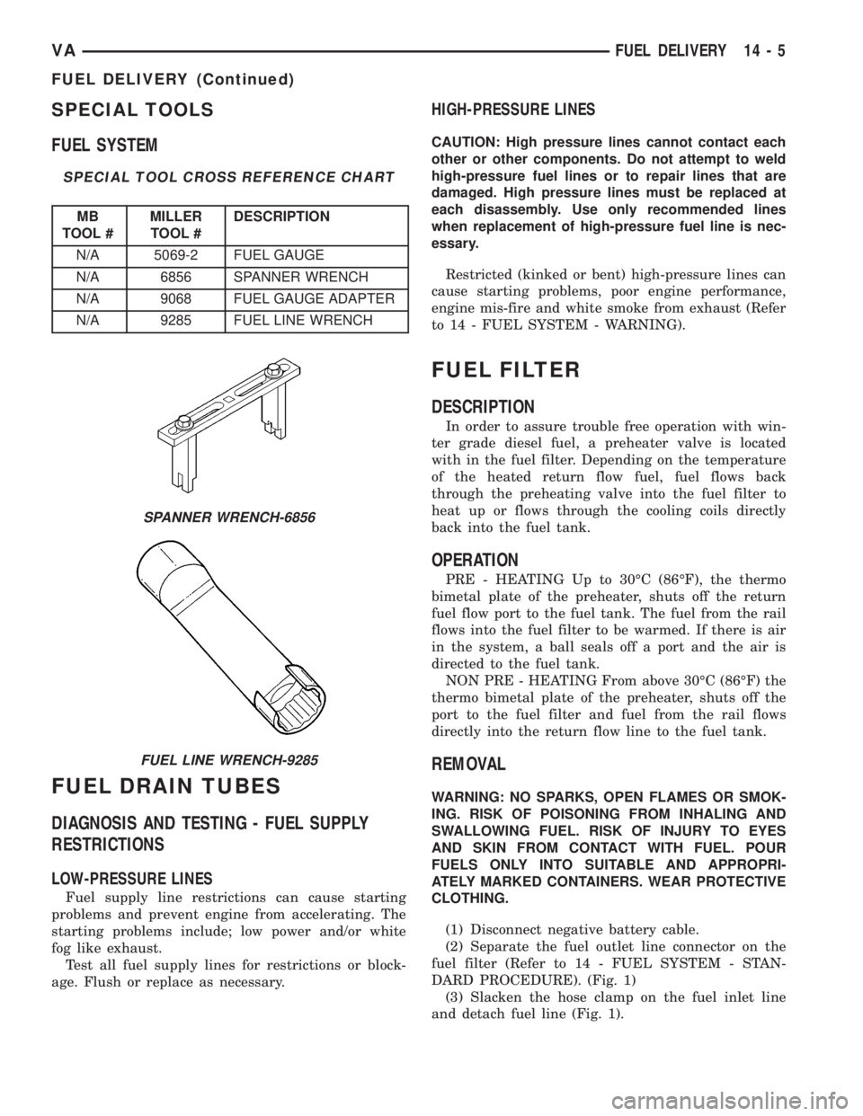
SPECIAL TOOLS
FUEL SYSTEM
SPECIAL TOOL CROSS REFERENCE CHART
MB
TOOL #MILLER
TOOL #DESCRIPTION
N/A 5069-2 FUEL GAUGE
N/A 6856 SPANNER WRENCH
N/A 9068 FUEL GAUGE ADAPTER
N/A 9285 FUEL LINE WRENCH
FUEL DRAIN TUBES
DIAGNOSIS AND TESTING - FUEL SUPPLY
RESTRICTIONS
LOW-PRESSURE LINES
Fuel supply line restrictions can cause starting
problems and prevent engine from accelerating. The
starting problems include; low power and/or white
fog like exhaust.
Test all fuel supply lines for restrictions or block-
age. Flush or replace as necessary.
HIGH-PRESSURE LINES
CAUTION: High pressure lines cannot contact each
other or other components. Do not attempt to weld
high-pressure fuel lines or to repair lines that are
damaged. High pressure lines must be replaced at
each disassembly. Use only recommended lines
when replacement of high-pressure fuel line is nec-
essary.
Restricted (kinked or bent) high-pressure lines can
cause starting problems, poor engine performance,
engine mis-fire and white smoke from exhaust (Refer
to 14 - FUEL SYSTEM - WARNING).
FUEL FILTER
DESCRIPTION
In order to assure trouble free operation with win-
ter grade diesel fuel, a preheater valve is located
with in the fuel filter. Depending on the temperature
of the heated return flow fuel, fuel flows back
through the preheating valve into the fuel filter to
heat up or flows through the cooling coils directly
back into the fuel tank.
OPERATION
PRE - HEATING Up to 30ÉC (86ÉF), the thermo
bimetal plate of the preheater, shuts off the return
fuel flow port to the fuel tank. The fuel from the rail
flows into the fuel filter to be warmed. If there is air
in the system, a ball seals off a port and the air is
directed to the fuel tank.
NON PRE - HEATING From above 30ÉC (86ÉF) the
thermo bimetal plate of the preheater, shuts off the
port to the fuel filter and fuel from the rail flows
directly into the return flow line to the fuel tank.
REMOVAL
WARNING: NO SPARKS, OPEN FLAMES OR SMOK-
ING. RISK OF POISONING FROM INHALING AND
SWALLOWING FUEL. RISK OF INJURY TO EYES
AND SKIN FROM CONTACT WITH FUEL. POUR
FUELS ONLY INTO SUITABLE AND APPROPRI-
ATELY MARKED CONTAINERS. WEAR PROTECTIVE
CLOTHING.
(1) Disconnect negative battery cable.
(2) Separate the fuel outlet line connector on the
fuel filter (Refer to 14 - FUEL SYSTEM - STAN-
DARD PROCEDURE). (Fig. 1)
(3) Slacken the hose clamp on the fuel inlet line
and detach fuel line (Fig. 1).
SPANNER WRENCH-6856
FUEL LINE WRENCH-9285
VAFUEL DELIVERY 14 - 5
FUEL DELIVERY (Continued)
Page 1040 of 1232
VISUAL INSPECTION BEFORE WATER LEAK TESTS
Verify that floor and body plugs are in place, body
drains are clear, and body components are properly
aligned and sealed. If component alignment or seal-
ing is necessary, refer to the appropriate section of
this group for proper procedures.
WATER LEAK TESTS
WARNING: DO NOT USE ELECTRIC SHOP LIGHTS
OR TOOLS IN WATER TEST AREA. PERSONAL
INJURY CAN RESULT.
When the conditions causing a water leak have
been determined, simulate the conditions as closely
as possible.
²If a leak occurs with the vehicle parked in a
steady light rain, flood the leak area with an open-
ended garden hose.
²If a leak occurs while driving at highway speeds
in a steady rain, test the leak area with a reasonable
velocity stream or fan spray of water. Direct the
spray in a direction comparable to actual conditions.
²If a leak occurs when the vehicle is parked on an
incline, hoist the end or side of the vehicle to simu-
late this condition. This method can be used when
the leak occurs when the vehicle accelerates, stops or
turns. If the leak occurs on acceleration, hoist the
front of the vehicle. If the leak occurs when braking,
hoist the back of the vehicle. If the leak occurs on left
turns, hoist the left side of the vehicle. If the leak
occurs on right turns, hoist the right side of the vehi-
cle. For hoisting recommendations (Refer to LUBRI-
CATION & MAINTENANCE/HOISTING -
STANDARD PROCEDURE).
WATER LEAK DETECTION
To detect a water leak point-of-entry, do a water
test and watch for water tracks or droplets forming
on the inside of the vehicle. If necessary, remove inte-
rior trim covers or panels to gain visual access to the
leak area. If the hose cannot be positioned without
being held, have someone help do the water test.
Some water leaks must be tested for a considerable
length of time to become apparent. When a leak
appears, find the highest point of the water track or
drop. The highest point usually will show the point of
entry. After leak point has been found, repair the
leak and water test to verify that the leak has
stopped.
Locating the entry point of water that is leaking
into a cavity between panels can be difficult. The
trapped water may splash or run from the cavity,
often at a distance from the entry point. Most water
leaks of this type become apparent after accelerating,
stopping, turning, or when on an incline.MIRROR INSPECTION METHOD
When a leak point area is visually obstructed, use
a suitable mirror to gain visual access. A mirror can
also be used to deflect light to a limited-access area
to assist in locating a leak point.
BRIGHT LIGHT LEAK TEST METHOD
Some water leaks in the luggage compartment can
be detected without water testing. Position the vehi-
cle in a brightly lit area. From inside the darkened
luggage compartment inspect around seals and body
seams. If necessary, have a helper direct a drop light
over the suspected leak areas around the luggage
compartment. If light is visible through a normally
sealed location, water could enter through the open-
ing.
PRESSURIZED LEAK TEST METHOD
When a water leak into the passenger compart-
ment cannot be detected by water testing, pressurize
the passenger compartment and soap test exterior of
the vehicle. To pressurize the passenger compart-
ment, close all doors and windows, start engine, and
set heater control to high blower in HEAT position. If
engine can not be started, connect a charger to the
battery to ensure adequate voltage to the blower.
With interior pressurized, apply dish detergent solu-
tion to suspected leak area on the exterior of the
vehicle. Apply detergent solution with spray device or
soft bristle brush. If soap bubbles occur at a body
seam, joint, seal or gasket, the leak entry point could
be at that location.
DIAGNOSIS AND TESTING - WIND NOISE
Wind noise is the result of most air leaks. Air leaks
can be caused by poor sealing, improper body compo-
nent alignment, body seam porosity, or missing plugs
in the engine compartment or door hinge pillar areas.
All body sealing points should be airtight in normal
driving conditions. Moving sealing surfaces will not
always seal airtight under all conditions. At times,
side glass or door seals will allow wind noise to be
noticed in the passenger compartment during high
cross winds. Over compensating on door or glass
adjustments to stop wind noise that occurs under
severe conditions can cause premature seal wear and
excessive closing or latching effort. After a repair pro-
cedure has been performed, test vehicle to verify
noise has stopped before returning vehicle to use.
VISUAL INSPECTION BEFORE TESTS
Verify that floor and body plugs are in place and
body components are aligned and sealed. If compo-
nent alignment or sealing is necessary, refer to the
appropriate section of this group for proper proce-
dures.
23 - 2 BODYVA
BODY (Continued)