Page 558 of 969

100IZ-01
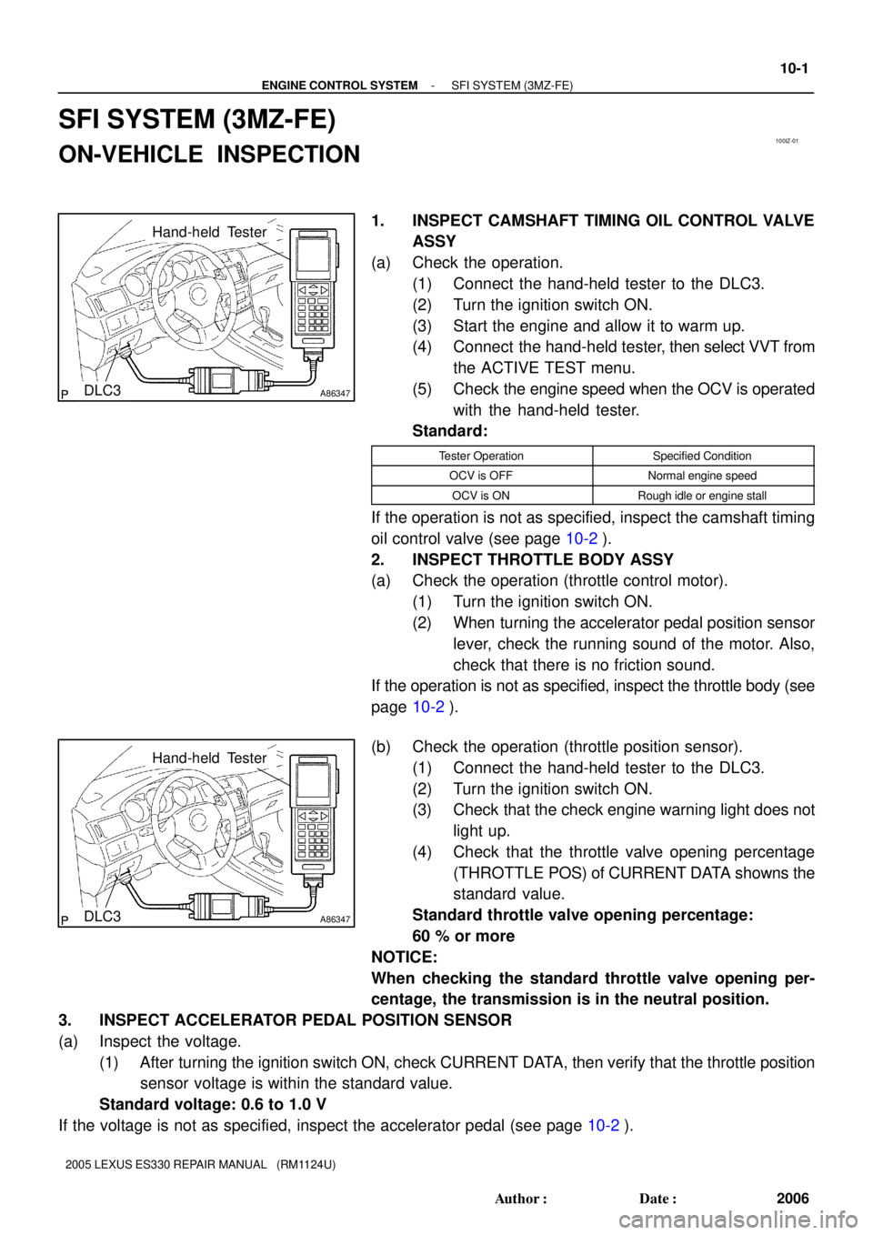
A86347DLC3
Hand-held Tester
A86347DLC3
Hand-held Tester
- ENGINE CONTROL SYSTEMSFI SYSTEM (3MZ-FE)
10-1
2006 Author�: Date�:
2005 LEXUS ES330 REPAIR MANUAL (RM1124U)
SFI SYSTEM (3MZ-FE)
ON-VEHICLE INSPECTION
1. INSPECT CAMSHAFT TIMING OIL CONTROL VALVE
ASSY
(a) Check the operation.
(1) Connect the hand-held tester to the DLC3.
(2) Turn the ignition switch ON.
(3) Start the engine and allow it to warm up.
(4) Connect the hand-held tester, then select VVT from
the ACTIVE TEST menu.
(5) Check the engine speed when the OCV is operated
with the hand-held tester.
Standard:
Tester OperationSpecified Condition
OCV is OFFNormal engine speed
OCV is ONRough idle or engine stall
If the operation is not as specified, inspect the camshaft timing
oil control valve (see page 10-2).
2. INSPECT THROTTLE BODY ASSY
(a) Check the operation (throttle control motor).
(1) Turn the ignition switch ON.
(2) When turning the accelerator pedal position sensor
lever, check the running sound of the motor. Also,
check that there is no friction sound.
If the operation is not as specified, inspect the throttle body (see
page 10-2).
(b) Check the operation (throttle position sensor).
(1) Connect the hand-held tester to the DLC3.
(2) Turn the ignition switch ON.
(3) Check that the check engine warning light does not
light up.
(4) Check that the throttle valve opening percentage
(THROTTLE POS) of CURRENT DATA showns the
standard value.
Standard throttle valve opening percentage:
60 % or more
NOTICE:
When checking the standard throttle valve opening per-
centage, the transmission is in the neutral position.
3. INSPECT ACCELERATOR PEDAL POSITION SENSOR
(a) Inspect the voltage.
(1) After turning the ignition switch ON, check CURRENT DATA, then verify that the throttle position
sensor voltage is within the standard value.
Standard voltage: 0.6 to 1.0 V
If the voltage is not as specified, inspect the accelerator pedal (see page 10-2).
Page 581 of 969

110XR-01
A62391
Circuit Opening Relay
- FUELFUEL SYSTEM (3MZ-FE)
11-1
2029 Author�: Date�:
2005 LEXUS ES330 REPAIR MANUAL (RM1124U)
FUEL SYSTEM (3MZ-FE)
PRECAUTION
1. PRECAUTION
(a) Before working on the fuel system, disconnect the engine wire No. 3 (battery negative terminal) from
battery.
(b) Do not smoke or work near open flame when working on the fuel system.
(c) Keep gasoline away from the rubber or leather parts.
2. DISCHARGE FUEL SYSTEM PRESSURE
CAUTION:
�Do not disconnect any parts of the fuel system pres-
sure until you have discharging the fuel system pres-
sure.
�Even after discharge the fuel pressure, place a shop
rag over fittings as you separate them in order to re-
duce risk of fuel spray on yourself or in the engine
compartment.
(a) Disconnect the engine wire No. 3 (battery negative termi-
nal).
(b) Remove the circuit opening relay from the engine room
relay block.
(c) Connect the engine wire No. 3 (battery negative terminal).
Torque: 5.4 NVm (55 kgfVcm, 48 in.Vlbf)
(d) Start the engine. After the engine has stopped on its own,
turn the ignition switch OFF.
HINT:
There is a case that DTC P0171 (system to lean) is output.
(e) Check that the engine does not start.
(f) Remove the fuel tank cap, then let the air out of the fuel
tank.
(g) Disconnect battery negative terminal.
(h) Reinstall the circuit opening relay.
3. FUEL SYSTEM
(a) When disconnecting the high fuel pressure line, a large
amount of gasoline will spill out. So observe these proce-
dures.
(1) Work in order to prevent gasoline from spilling out.
(2) Disconnect the fuel pump tube (see page 11-20).
(3) Drain the fuel remaining inside the fuel pump tube.
Page 587 of 969

A86347DLC3
Hand-held Tester
A62390
FP
+B
- FUELFUEL SYSTEM (3MZ-FE)
11-7
2035 Author�: Date�:
2005 LEXUS ES330 REPAIR MANUAL (RM1124U)
2. CHECK FUEL PUMP OPERATION AND FUEL LEAK
(a) When using the hand-held tester.
(1) Connect the hand-held tester to the DLC3.
(2) Turn the ignition switch ON and the hand-held tes-
ter ON.
NOTICE:
Do not start the engine.
(3) Select the ACTIVE TEST mode on the hand-held
tester.
(4) If you need help to select the ACTIVE TEST mode
on the hand-held tester, refer to the hand-held tes-
ter operator's manual.
(b) When not using the hand-held tester.
(1) Remove the circuit opening relay.
(2) Using a service wire, connect terminals FP and +B
of the engine room relay block.
NOTICE:
Pay due attention to the terminal connecting position to
avoid a malfunction.
(3) Turn the ignition switch ON, and check that the fuel
pump operates.
NOTICE:
Do not start the engine.
(c) Check that there are no fuel leaks after doing mainte-
nance anywhere on the fuel system.
Page 616 of 969

120C1-02
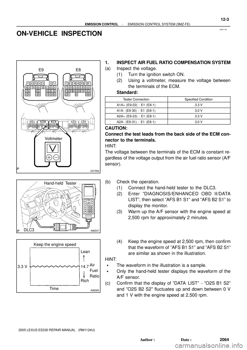
G37992
Voltmeter E9 E8
A86347DLC3
Hand-held Tester
A86385
Lean
14.7 3.3 V
RichAir
Fuel
Ratio
Time Keep the engine speed
- EMISSION CONTROLEMISSION CONTROL SYSTEM (3MZ-FE)
12-3
2064 Author�: Date�:
2005 LEXUS ES330 REPAIR MANUAL (RM1124U)
ON-VEHICLE INSPECTION
1. INSPECT AIR FUEL RATIO COMPENSATION SYSTEM
(a) Inspect the voltage.
(1) Turn the ignition switch ON.
(2) Using a voltmeter, measure the voltage between
the terminals of the ECM.
Standard:
Tester ConnectionSpecified Condition
A1A+ (E9-22) - E1 (E8-1)3.3 V
A1A- (E9-30) - E1 (E8-1)3.0 V
A2A+ (E9-23) - E1 (E8-1)3.3 V
A2A- (E9-31) - E1 (E8-1)3.0 V
CAUTION:
Connect the test leads from the back side of the ECM con-
nector to the terminals.
HINT:
The voltage between the terminals of the ECM is constant re-
gardless of the voltage output from the air fuel ratio sensor (A/F
sensor).
(b) Check the operation.
(1) Connect the hand-held tester to the DLC3.
(2) Enter ºDIAGNOSIS/ENHANCED OBD II/DATA
LISTº, then select ºAFS B1 S1º and ºAFS B2 S1º to
display the monitor.
(3) Warm up the A/F sensor with the engine speed at
2,500 rpm for approximately 2 minutes.
(4) Keep the engine speed at 2,500 rpm, then confirm
that the waveform of ºAFS B1 S1º and ºAFS B2 S1º
are similar as shown in the illustration.
HINT:
�The waveform in the illustration is a sample.
�Only the hand-held tester displays the waveform of the
A/F sensor.
(c) Confirm that the display of ºDATA LISTº - ºO2S B1 S2º
and ºO2S B2 S2º fluctuates up and down between 0 V
and 1 V with the engine speed at 2,500 rpm.
Page 619 of 969

A86347DLC3
Hand-held Tester
A86349Battery
A59501
Pressure Gauge
Pressure
A52634
Fuel Tank CapPressure Gauge
12-6
- EMISSION CONTROLEMISSION CONTROL SYSTEM (3MZ-FE)
2067 Author�: Date�:
2005 LEXUS ES330 REPAIR MANUAL (RM1124U)
(j) If you have the hand-held tester:
Force the VSV for CCV to operate.
(1) Connect the hand-held tester to the DLC3.
(2) Turn the ignition switch ON.
(3) Turn the hand-held tester ON.
(4) Use the ACTIVE TEST mode on the hand-held tes-
ter to operate the VSV for CCV.
NOTICE:
Do not start the engine during this operation.
HINT:
If the check is not completed within 10 minutes, the forced close
of the VSV for CCV will be tested.
(k) If you have no hand-held tester:
Force the VSV for CCV to operate.
(1) Disconnect the VSV for CCV connector.
(2) Connect the positive (+) and negative (-) leads of
the battery to the VSV for CCV terminals.
(l) Check the pressure.
(1) Add the pressure (13.5 to 15.5 in.Aq) from the
EVAP service port.
Pressure:
2 minutes after the pressure is added, the gauge
should be over 7.7 to 8.8 in.Aq.
HINT:
If you cannot add the pressure, it can be concluded that the
hose which connects the VSV for EVAP canister fuel tank is
slipped off or the VSV is open.
(2) Check if the pressure decreases when the fuel tank
cap is removed while adding the pressure.
HINT:
If the pressure does not decrease when the filler cap is re-
moved, it can be concluded that the hose which connects the
service port to the fuel tank is blocked, etc.
(m) If you have the hand-held tester:
Return to the normal VSV for CCV operation.
(1) Turn the ignition switch ON.
(2) Disconnect the hand-held tester from the DLC3.
(n) If you have no hand-held tester:
Return to the normal VSV for CCV operation.
(1) Disconnect the positive (+) and negative (-) leads
of the battery to the VSV for CCV terminals.
(2) Reconnect the VSV for CCV connector.
Page 621 of 969

A86352
Air
A86344
VoltmeterE10 12-8
- EMISSION CONTROLEMISSION CONTROL SYSTEM (3MZ-FE)
2069 Author�: Date�:
2005 LEXUS ES330 REPAIR MANUAL (RM1124U)
(8) Remove the vinyl or plastic bag from the fuel tank
to filler pipe port, then check that the pressure
drops.
If the pressure does not drop, replace the fuel tank.
(9) Drain fuel from the fuel tank.
(10) Reinstall the fuel tank vent hose to the fuel tank (see
page 11-28).
(11) Reinstall the fuel tank (see page 11-28).
7. CHECK AIR INLET LINE
(a) Disconnect the fuel tank vent hose (see page 12-18).
(b) Check that there is ventilation in fuel tank vent hose.
If necessary, replace the charcoal canister filter.
(c) Reconnect the fuel tank vent hose (see page 12-18).
8. INSPECT VAPOR PRESSURE SENSOR
(a) Inspect the voltage (power source).
(1) Turn the ignition switch ON.
(2) Using a voltmeter, measure the voltage between
the terminals of the ECM.
Voltage:
Tester ConnectionSpecified Condition
VC (E10-18) - E2 (E10-28)4.5 to 5.5 V
CAUTION:
Connect the test leads from the back side of the ECM con-
nector to the terminals.
(3) Turn the ignition switch OFF.
Page 622 of 969
G37993
Voltmeter E10 E6
- EMISSION CONTROLEMISSION CONTROL SYSTEM (3MZ-FE)
12-9
2070 Author�: Date�:
2005 LEXUS ES330 REPAIR MANUAL (RM1124U)
(b) Inspect the voltage (power output).
(1) Turn the ignition switch ON.
(2) Remove the fuel tank cap.
(3) Using a voltmeter, measure the voltage between
the terminals of the ECM.
Voltage:
Tester ConnectionSpecified Condition
PTNK (E6-21) - E2 (E10-28)3.0 to 3.6 V
CAUTION:
Connect the test leads from the back side of the ECM con-
nector to the terminals.
(4) Reinstall the fuel tank cap.
(5) Turn the ignition switch OFF.
Page 652 of 969
160QD-01
A86555
A86554
A86556
B09432
- COOLINGCOOLING FAN SYSTEM (3MZ-FE)
16-5
2283 Author�: Date�:
2005 LEXUS ES330 REPAIR MANUAL (RM1124U)
COOLING FAN SYSTEM (3MZ-FE)
ON-VEHICLE INSPECTION
1. CHECK COOLING FAN OPERATION AT LOW TEM-
PERATURE (Below 83�C (181�F))
(a) Turn the ignition switch ON.
(b) Check that the fan and fan No. 2 stops.
If not, check the cooling fan relays and temperature detect
switches.
(c) Disconnect the temperature detect switch connector.
(d) Connect the terminals of the temperature detect switch
wire connector.
(e) Check that the fan rotates at high speed.
If not, check the cooling fan relay and fan.
(f) Reconnect the temperature detect switch connector.
(g) Disconnect the temperature detect switch No. 2 connec-
tor.
(h) Ground the terminal on the temperature detect switch No.
2 wire harness side connector.