Page 495 of 969
A78390
Camshaft Bearing Cap No. 2
Camshaft Bearing Cap No. 3
Camshaft Bearing Cap No. 6
Camshaft Bearing Cap No. 5
16 (163, 12)
x10
Camshaft
8.0 (80, 71 in.Vlbf)
8.4 (85, 74 in.Vlbf)
8.0 (80, 71 in.Vlbf)
16 (163, 12)
Ignition Coil AssyEngine Wire
Engine Wire
Cylinder Head Cover Gasket Cylinder Head Cover Sub-assy
Camshaft Bearing
Cap No. 2
x10Camshaft Bearing Cap No. 4
Camshaft Bearing Cap No. 2
No. 2 CamshaftCamshaft Bearing Cap No. 1
N´m (kgf´cm, ft´lbf)
: Specified torque
� Non-reusable part Camshaft Setting
Oil Seal �
19 (189, 14)
� Cylinder Head GasketCylinder Head Sub-assy
1st: 54 (550, 40)
2st: Turn 90� See page 14-120
x9
x8
- ENGINE MECHANICALCYLINDER HEAD GASKET (3MZ-FE)
14-1 19
2211 Author�: Date�:
2005 LEXUS ES330 REPAIR MANUAL (RM1124U)
Page 497 of 969
A86572
1
542
36
A78401
A78716
Front
A78717
Front
1
23
8
7
6
5
4
- ENGINE MECHANICALCYLINDER HEAD GASKET (3MZ-FE)
14-121
2213 Author�: Date�:
2005 LEXUS ES330 REPAIR MANUAL (RM1124U)
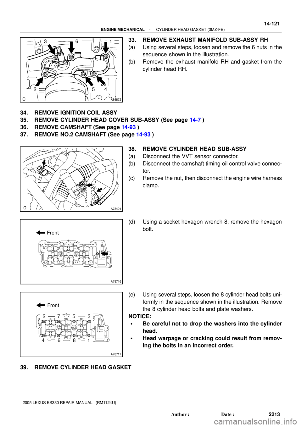
33. REMOVE EXHAUST MANIFOLD SUB-ASSY RH
(a) Using several steps, loosen and remove the 6 nuts in the
sequence shown in the illustration.
(b) Remove the exhaust manifold RH and gasket from the
cylinder head RH.
34. REMOVE IGNITION COIL ASSY
35. REMOVE CYLINDER HEAD COVER SUB-ASSY (See page 14-7)
36. REMOVE CAMSHAFT (See page 14-93)
37. REMOVE NO.2 CAMSHAFT (See page 14-93)
38. REMOVE CYLINDER HEAD SUB-ASSY
(a) Disconnect the VVT sensor connector.
(b) Disconnect the camshaft timing oil control valve connec-
tor.
(c) Remove the nut, then disconnect the engine wire harness
clamp.
(d) Using a socket hexagon wrench 8, remove the hexagon
bolt.
(e) Using several steps, loosen the 8 cylinder head bolts uni-
formly in the sequence shown in the illustration. Remove
the 8 cylinder head bolts and plate washers.
NOTICE:
�Be careful not to drop the washers into the cylinder
head.
�Head warpage or cracking could result from remov-
ing the bolts in an incorrect order.
39. REMOVE CYLINDER HEAD GASKET
Page 499 of 969
A78716
Front
A86572
6
235
41
- ENGINE MECHANICALCYLINDER HEAD GASKET (3MZ-FE)
14-123
2215 Author�: Date�:
2005 LEXUS ES330 REPAIR MANUAL (RM1124U)
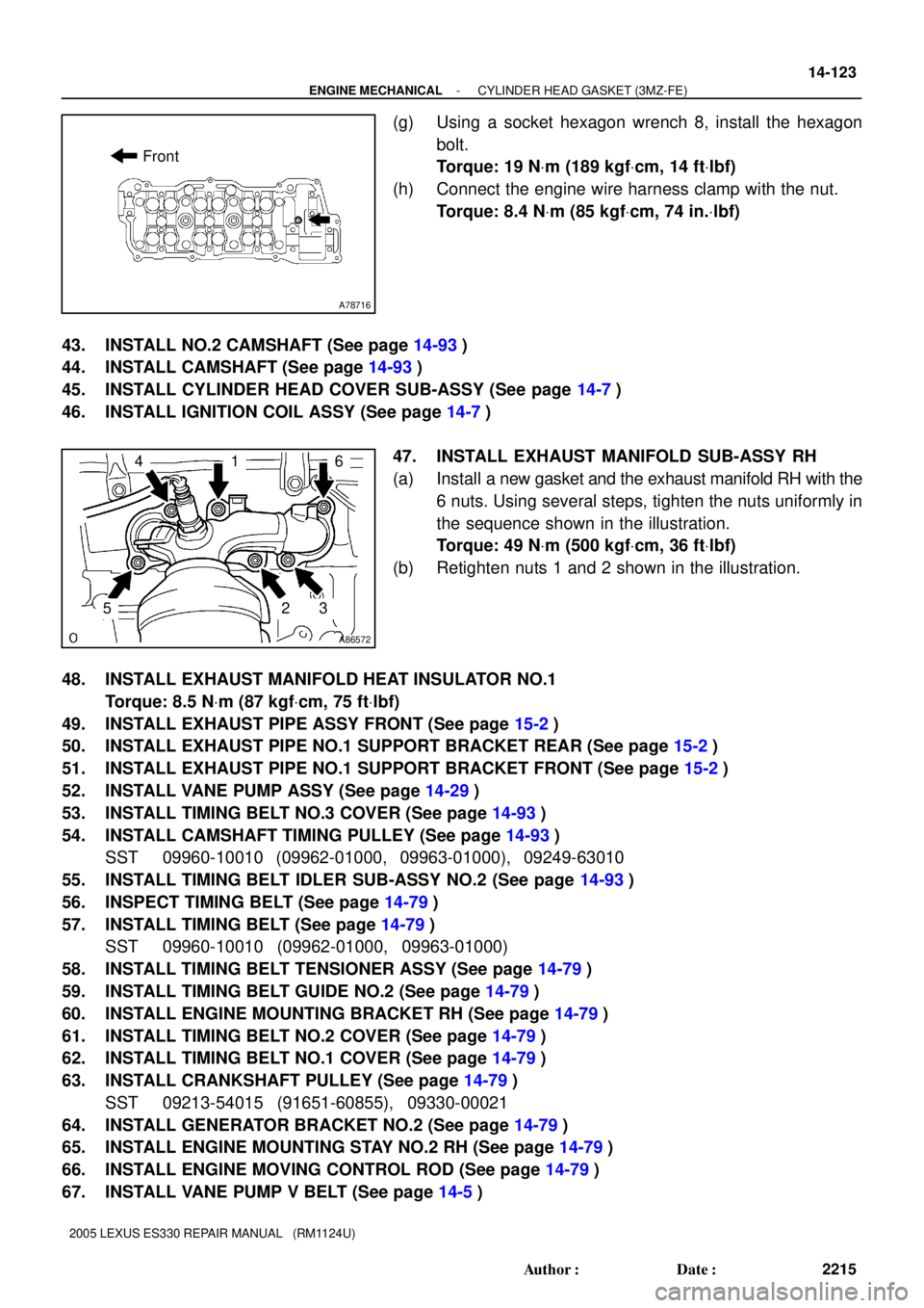
(g) Using a socket hexagon wrench 8, install the hexagon
bolt.
Torque: 19 NVm (189 kgfVcm, 14 ftVlbf)
(h) Connect the engine wire harness clamp with the nut.
Torque: 8.4 NVm (85 kgfVcm, 74 in.Vlbf)
43. INSTALL NO.2 CAMSHAFT (See page 14-93)
44. INSTALL CAMSHAFT (See page 14-93)
45. INSTALL CYLINDER HEAD COVER SUB-ASSY (See page 14-7)
46. INSTALL IGNITION COIL ASSY (See page 14-7)
47. INSTALL EXHAUST MANIFOLD SUB-ASSY RH
(a) Install a new gasket and the exhaust manifold RH with the
6 nuts. Using several steps, tighten the nuts uniformly in
the sequence shown in the illustration.
Torque: 49 NVm (500 kgfVcm, 36 ftVlbf)
(b) Retighten nuts 1 and 2 shown in the illustration.
48. INSTALL EXHAUST MANIFOLD HEAT INSULATOR NO.1
Torque: 8.5 NVm (87 kgfVcm, 75 ftVlbf)
49. INSTALL EXHAUST PIPE ASSY FRONT (See page 15-2)
50. INSTALL EXHAUST PIPE NO.1 SUPPORT BRACKET REAR (See page 15-2)
51. INSTALL EXHAUST PIPE NO.1 SUPPORT BRACKET FRONT (See page 15-2)
52. INSTALL VANE PUMP ASSY (See page 14-29)
53. INSTALL TIMING BELT NO.3 COVER (See page 14-93)
54. INSTALL CAMSHAFT TIMING PULLEY (See page 14-93)
SST 09960-10010 (09962-01000, 09963-01000), 09249-63010
55. INSTALL TIMING BELT IDLER SUB-ASSY NO.2 (See page 14-93)
56. INSPECT TIMING BELT (See page 14-79)
57. INSTALL TIMING BELT (See page 14-79)
SST 09960-10010 (09962-01000, 09963-01000)
58. INSTALL TIMING BELT TENSIONER ASSY (See page 14-79)
59. INSTALL TIMING BELT GUIDE NO.2 (See page 14-79)
60. INSTALL ENGINE MOUNTING BRACKET RH (See page 14-79)
61. INSTALL TIMING BELT NO.2 COVER (See page 14-79)
62. INSTALL TIMING BELT NO.1 COVER (See page 14-79)
63. INSTALL CRANKSHAFT PULLEY (See page 14-79)
SST 09213-54015 (91651-60855), 09330-00021
64. INSTALL GENERATOR BRACKET NO.2 (See page 14-79)
65. INSTALL ENGINE MOUNTING STAY NO.2 RH (See page 14-79)
66. INSTALL ENGINE MOVING CONTROL ROD (See page 14-79)
67. INSTALL VANE PUMP V BELT (See page 14-5)
Page 500 of 969
14-124
- ENGINE MECHANICALCYLINDER HEAD GASKET (3MZ-FE)
2216 Author�: Date�:
2005 LEXUS ES330 REPAIR MANUAL (RM1124U)
68. INSTALL V (COOLER COMPRESSOR TO CRANKSHAFT PULLEY) BELT NO.1
(See page 14-5)
69. INSPECT DRIVE BELT DEFLECTION AND TENSION (See page 14-1)
70. INSTALL WATER OUTLET (See page 10-16)
71. INSTALL INTAKE MANIFOLD (See page 10-16)
72. INSTALL INTAKE AIR SURGE TANK (See page 11-13)
73. INSTALL EMISSION CONTROL VALVE SET (See page 11-13)
74. INSTALL AIR CLEANER CAP SUB-ASSY (See page 10-1 1)
75. CHECK CONNECTION OF VACUUM HOSE (See page 14-29)
76. INSTALL V-BANK COVER SUB-ASSY (See page 10-1 1)
77. INSTALL FRONT SUSPENSION UPPER BRACE CENTER (W/O TEMS) (See page 10-1 1)
78. INSTALL FRONT WHEEL RH (See page 14-5)
79. ADD ENGINE OIL (See page 17-20)
80. ADD ENGINE COOLANT (See page 16-9)
81. CHECK FOR ENGINE OIL LEAKS
82. CHECK FOR ENGINE COOLANT LEAKS (See page 16-1)
83. INSPECT FOR FUEL LEAKS
84. CHECK FOR EXHAUST GAS LEAKS
85. INSPECT IGNITION TIMING (See page 14-1)
SST 09843-18040
86. INSPECT ENGINE IDLE SPEED (See page 14-1)
87. INSPECT COMPRESSION (See page 14-1)
SST 09992-00500
88. INSPECT CO/HC (See page 14-1)
89. SYSTEM INITIALIZATION (See page 19-15)
Page 508 of 969
A86599
8.0 (80, 71 in.Vlbf)
Ignition Coil Assy
Cylinder Head Cover Sub-assy LH
8.4 (85, 74 in.Vlbf)
Engine Wire
Cylinder Head Cover Gasket No. 2
Camshaft Bearing
Cap No. 2
16 (163, 12)
Camshaft Bearing Cap No. 2Camshaft Bearing Cap No. 3
Camshaft Bearing
Cap No. 6 Camshaft Bearing Cap No. 5
Camshaft Bearing Cap No. 4
Camshaft Bearing Cap No. 2
16 (163, 12)
Camshaft Bearing Cap No. 1
No. 4 Camshaft Sub-assy
N´m (kgf´cm, ft´lbf)
: Specified torque� Non-reusable part
8.0 (80, 71 in.Vlbf)
Camshaft Setting
Oil Seal �
19 (189, 14)
� Cylinder Head
Gasket No. 2
1st: 54 (550, 40)
2st: Turn 90� See page 14-133
5.4 (55, 48 in.Vlbf)
5.4 (55, 48 in.Vlbf)
No. 3 Camshaft Sub-assy
Water Inlet Pipe
20 (199, 14)
� O-ring
Cylinder Head LH
x9
x10
x8 x10 14-132
- ENGINE MECHANICALCYLINDER HEAD GASKET NO.2 (3MZ-FE)
2224 Author�: Date�:
2005 LEXUS ES330 REPAIR MANUAL (RM1124U)
Page 510 of 969
A86575
A78718
Front
A78719
Front
1
23
8
7
6
5
4
A79822
Front 14-134
- ENGINE MECHANICALCYLINDER HEAD GASKET NO.2 (3MZ-FE)
2226 Author�: Date�:
2005 LEXUS ES330 REPAIR MANUAL (RM1124U)
34. REMOVE WATER INLET PIPE (See page 16-16)
35. REMOVE IGNITION COIL ASSY
36. REMOVE CYLINDER HEAD COVER SUB-ASSY LH (See page 14-7)
37. REMOVE NO.3 CAMSHAFT SUB-ASSY (See page 14-107)
38. REMOVE NO.4 CAMSHAFT SUB-ASSY (See page 14-107)
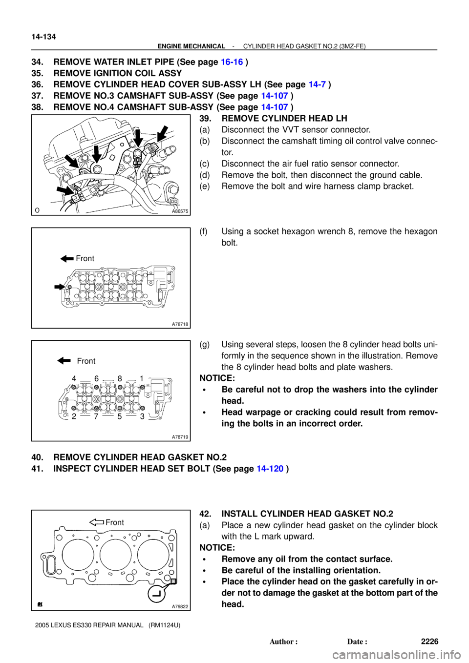
39. REMOVE CYLINDER HEAD LH
(a) Disconnect the VVT sensor connector.
(b) Disconnect the camshaft timing oil control valve connec-
tor.
(c) Disconnect the air fuel ratio sensor connector.
(d) Remove the bolt, then disconnect the ground cable.
(e) Remove the bolt and wire harness clamp bracket.
(f) Using a socket hexagon wrench 8, remove the hexagon
bolt.
(g) Using several steps, loosen the 8 cylinder head bolts uni-
formly in the sequence shown in the illustration. Remove
the 8 cylinder head bolts and plate washers.
NOTICE:
�Be careful not to drop the washers into the cylinder
head.
�Head warpage or cracking could result from remov-
ing the bolts in an incorrect order.
40. REMOVE CYLINDER HEAD GASKET NO.2
41. INSPECT CYLINDER HEAD SET BOLT (See page 14-120)
42. INSTALL CYLINDER HEAD GASKET NO.2
(a) Place a new cylinder head gasket on the cylinder block
with the L mark upward.
NOTICE:
�Remove any oil from the contact surface.
�Be careful of the installing orientation.
�Place the cylinder head on the gasket carefully in or-
der not to damage the gasket at the bottom part of the
head.
Page 511 of 969
A78719
1
2
3
4
5
67
8
Front
A78730
90�
Front
Painted Mark
A78718
Front
- ENGINE MECHANICALCYLINDER HEAD GASKET NO.2 (3MZ-FE)
14-135
2227 Author�: Date�:
2005 LEXUS ES330 REPAIR MANUAL (RM1124U)
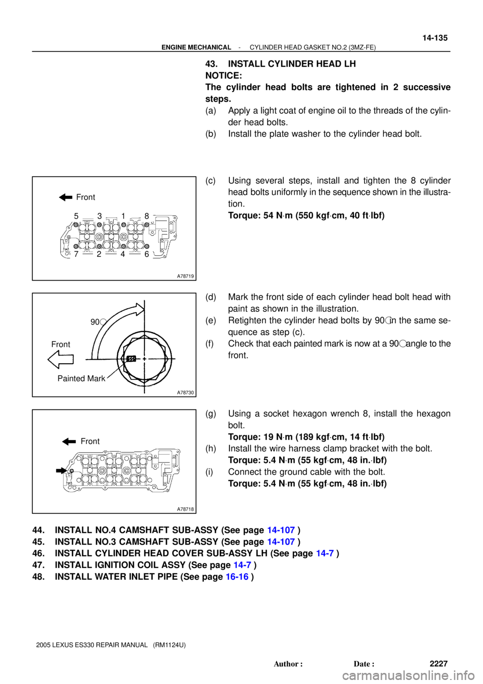
43. INSTALL CYLINDER HEAD LH
NOTICE:
The cylinder head bolts are tightened in 2 successive
steps.
(a) Apply a light coat of engine oil to the threads of the cylin-
der head bolts.
(b) Install the plate washer to the cylinder head bolt.
(c) Using several steps, install and tighten the 8 cylinder
head bolts uniformly in the sequence shown in the illustra-
tion.
Torque: 54 NVm (550 kgfVcm, 40 ftVlbf)
(d) Mark the front side of each cylinder head bolt head with
paint as shown in the illustration.
(e) Retighten the cylinder head bolts by 90�in the same se-
quence as step (c).
(f) Check that each painted mark is now at a 90� angle to the
front.
(g) Using a socket hexagon wrench 8, install the hexagon
bolt.
Torque: 19 NVm (189 kgfVcm, 14 ftVlbf)
(h) Install the wire harness clamp bracket with the bolt.
Torque: 5.4 NVm (55 kgfVcm, 48 in.Vlbf)
(i) Connect the ground cable with the bolt.
Torque: 5.4 NVm (55 kgfVcm, 48 in.Vlbf)
44. INSTALL NO.4 CAMSHAFT SUB-ASSY (See page 14-107)
45. INSTALL NO.3 CAMSHAFT SUB-ASSY (See page 14-107)
46. INSTALL CYLINDER HEAD COVER SUB-ASSY LH (See page 14-7)
47. INSTALL IGNITION COIL ASSY (See page 14-7)
48. INSTALL WATER INLET PIPE (See page 16-16)
Page 513 of 969
- ENGINE MECHANICALCYLINDER HEAD GASKET NO.2 (3MZ-FE)
14-137
2229 Author�: Date�:
2005 LEXUS ES330 REPAIR MANUAL (RM1124U)
85. CHECK FOR EXHAUST GAS LEAKS
86. INSPECT IGNITION TIMING (See page 14-1)
SST 09843-18040
87. INSPECT ENGINE IDLE SPEED (See page 14-1)
88. INSPECT COMPRESSION (See page 14-1)
SST 09992-00500
89. INSPECT CO/HC (See page 14-1)
90. SYSTEM INITIALIZATION (See page 19-15)