Page 336 of 969
33-10
- PARKING BRAKEPARKING BRAKE CABLE ASSY NO.1
2506 Author�: Date�:
2005 LEXUS ES330 REPAIR MANUAL (RM1124U)
18. INSTALL YAWRATE SENSOR (W/ VSC)(See page 32-59)
19. INSTALL CONSOLE BOX DUCT NO.1
20. INSTALL AIR DUCT REAR NO.2
21. INSTALL AIR DUCT REAR NO.1
22. INSTALL INSTRUMENT PANEL FINISH PANEL END LH
23. INSTALL INSTRUMENT PANEL FINISH PANEL END RH
24. INSTALL RR CONSOLE BOX
25. INSTALL CONSOLE BOX CARPET
26. INSTALL CONSOLE PANEL UPPER REAR
27. INSTALL INSTRUMENT PANEL SUB-ASSY LOWER
28. INSTALL INSTRUMENT PANEL UNDER COVER SUB-ASSY NO.1
29. INSTALL INSTRUMENT PANEL INSERT SUB-ASSY LOWER LH
30. INSTALL INSTRUMENT PANEL SUB-ASSY UPPER
31. INSTALL FRONT DOOR SCUFF PLATE LH
32. INSTALL FRONT DOOR SCUFF PLATE RH
33. INSPECT AND ADJUST PARKING BRAKE PEDAL TRAVEL(See page 33-2)
34. CHECK VSC SENSOR SIGNAL (W/ VSC)(See page 05-471)
Page 340 of 969

PARKING BRAKE CABLE ASSY NO.4
REPLACEMENT
H")
3305L-02
C90470
Turn
Buckle
C90464
C90464
33-14
- PARKING BRAKEPARKING BRAKE CABLE ASSY NO.4
2510 Author�: Date�:
2005 LEXUS ES330 REPAIR MANUAL (RM1124U)
PARKING BRAKE CABLE ASSY NO.4
REPLACEMENT
HINT:
COMPONENTS: See page 71-8 and 33-3
1. REMOVE CONSOLE PANEL UPPER REAR(See page 71-1 1)
2. REMOVE CONSOLE BOX CARPET
3. REMOVE RR CONSOLE BOX(See page 71-1 1)
4. REMOVE CONSOLE BOX MOUNTING BRACKET NO.2
(a) Remove the 2 bolts and console box mounting bracket No.2.
5. REMOVE YAWRATE SENSOR (W/ VSC)(See page 32-59)
6. REMOVE PARKING BRAKE CABLE ASSY NO.4
(a) Loosen the turn buckle, disconnect the parking brake
cable assy No.4 from the parking brake cable assy No.1.
(b) Disconnect the parking brake cable assy No.4 from the
parking brake equalizer.
(c) Remove the 2 bolts and parking brake cable assy No.4.
7. INSTALL PARKING BRAKE CABLE ASSY NO.4
(a) Install the parking brake cable No.4 with the 2 bolts.
Torque: 12.5 NVm (128 kgfVcm, 9 ftVlbf)
(b) Connect the parking brake cable assy No.4 to the parking
brake equalizer.
Page 341 of 969
C90470
Turn
Buckle
- PARKING BRAKEPARKING BRAKE CABLE ASSY NO.4
33-15
2511 Author�: Date�:
2005 LEXUS ES330 REPAIR MANUAL (RM1124U)
(c) Tighten the turn buckle, connect the parking brake cable
assy No.4 to the parking brake cable assy No.1.
Torque: 5.4 NVm (55 kgfVcm, 48 in.Vlbf)
8. INSTALL YAWRATE SENSOR (W/ VSC)(See page 32-59)
9. INSTALL CONSOLE BOX MOUNTING BRACKET NO.2
(a) Install the console box mounting bracket No.2 with the 2 bolts.
Torque: 12.5 NVm (128 kgfVcm, 9 ftVlbf)
10. INSTALL RR CONSOLE BOX
11. INSTALL CONSOLE BOX CARPET
12. INSTALL CONSOLE PANEL UPPER REAR
13. INSPECT AND ADJUST PARKING BRAKE PEDAL TRAVEL
14. CHECK VSC SENSOR SIGNAL (W/ VSC)(See page 05-471)
Page 351 of 969
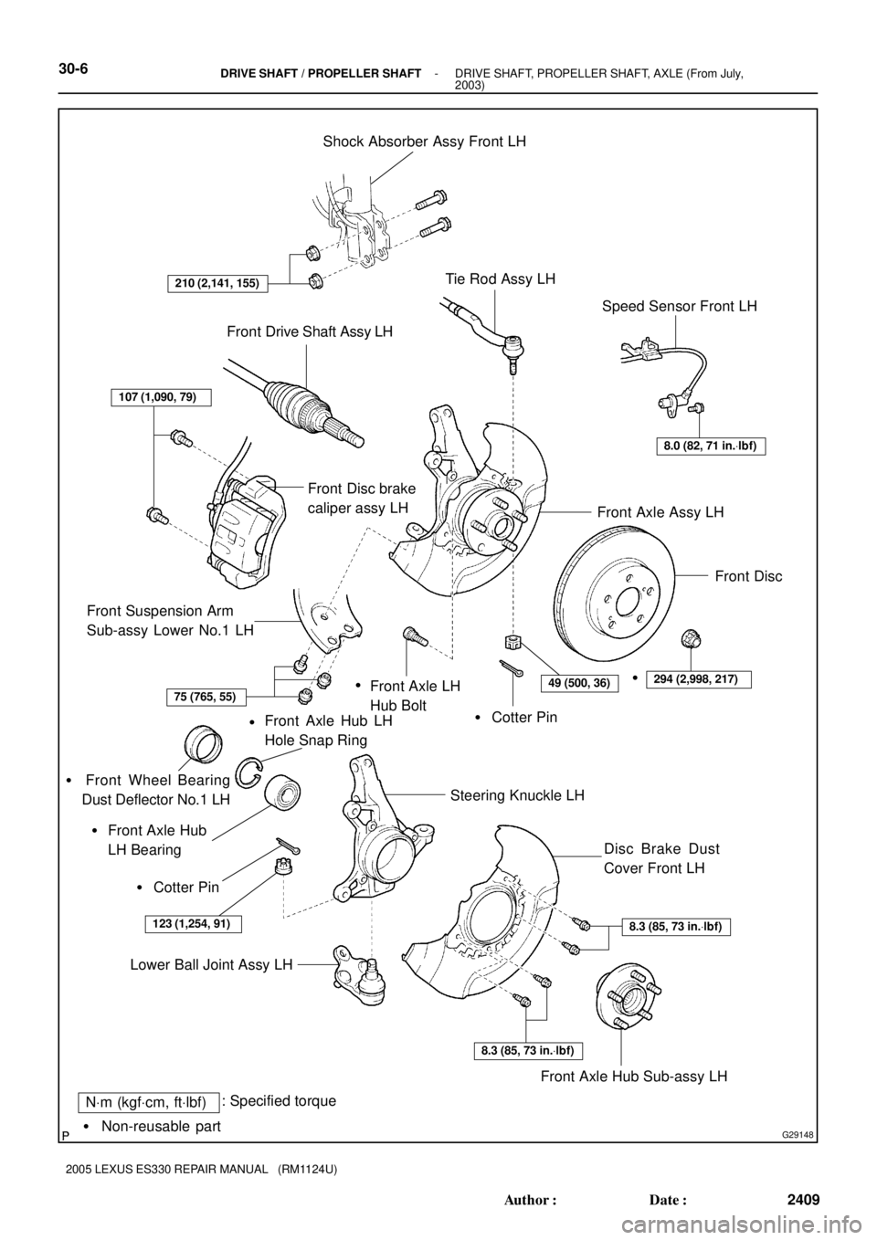
G29148
NVm (kgfVcm, ftVlbf): Specified torque
� Non-reusable partShock Absorber Assy Front LH
Tie Rod Assy LH
Speed Sensor Front LH
Front Suspension Arm
Sub-assy Lower No.1 LH
� Cotter Pin Front Axle LH
Hub Bolt
Steering Knuckle LH
Lower Ball Joint Assy LHFront Axle Assy LH Front Drive Shaft Assy LH
210 (2,141, 155)
8.0 (82, 71 in.Vlbf)
Front Disc
107 (1,090, 79)
75 (765, 55)49 (500, 36)294 (2,998, 217)
Front Axle Hub LH
Hole Snap Ring
� Cotter Pin�
Front Axle Hub
LH Bearing �
123 (1,254, 91)
Disc Brake Dust
Cover Front LH
Front Axle Hub Sub-assy LH
8.3 (85, 73 in.Vlbf)
8.3 (85, 73 in.Vlbf)
��
� Front Wheel Bearing
Dust Deflector No.1 LH
Front Disc brake
caliper assy LH
30-6- DRIVE SHAFT / PROPELLER SHAFTDRIVE SHAFT, PROPELLER SHAFT, AXLE (From July,
2003)
2409 Author�: Date�:
2005 LEXUS ES330 REPAIR MANUAL (RM1124U)
Page 353 of 969

2411 Author�: Date�:
2005 LEXUS ES330 REPAIR MANUAL (RM1124U)
FRONT DRIVE SHAFT (From")
300M5-01
C91611
SST
F40136
C83022
F40147
30-8
- DRIVE SHAFT / PROPELLER SHAFTFRONT DRIVE SHAFT (From July, 2003)
2411 Author�: Date�:
2005 LEXUS ES330 REPAIR MANUAL (RM1124U)
FRONT DRIVE SHAFT (From July, 2003)
OVERHAUL
HINT:
�COMPONENTS: See page 30-4
�Overhaul the RH side following the same procedures as for the LH side.
1. DRAIN AUTOMATIC TRANSAXLE FLUID
2. REMOVE FRONT WHEEL
3. REMOVE FRONT AXLE HUB LH NUT
(a) Using SST and a hammer, unstake the staked part of the
front axle hub LH nut.
SST 09930-00010
NOTICE:
Loosen the staked part of the lock nut completely, other-
wise the screw of the drive shaft may be damaged.
(b) While applying the brake, remove the front axle hub LH
nut.
4. DISCONNECT FRONT STABILIZER LINK ASSY LH
(a) Remove the nut, and separate the stabilizer link assy LH.
HINT:
If the ball joint turns together with the nut, use a hexagon
wrench (6 mm) to hold the stud.
5. DISCONNECT SPEED SENSOR FRONT LH
(a) Remove the bolt and clip, and separate the sensor wire
and hose from the shock absorber.
NOTICE:
Be careful not to damage the speed sensor.
(b) Remove the bolt, and separate the speed sensor front LH
from the steering knuckle.
NOTICE:
Prevent foreign matter from adhering to the speed sensor.
Page 364 of 969

30-19
2422 Author�: Date�:
2005 LEXUS ES330 REPAIR MANUAL (RM1124U)
FRONT AXLE HUB SUB-A")
300M6-02
C91612
C83023
F40153
SST
- DRIVE SHAFT / PROPELLER SHAFTFRONT AXLE HUB SUB-ASSY LH (From July, 2003)
30-19
2422 Author�: Date�:
2005 LEXUS ES330 REPAIR MANUAL (RM1124U)
FRONT AXLE HUB SUB-ASSY LH (From July, 2003)
REPLACEMENT
HINT:
�Replace the RH side using the same procedures as for the LH side.
1. REMOVE FRONT WHEEL
2. REMOVE FRONT AXLE HUB LH NUT (SEE PAGE 30-8)
SST 09930-00010
3. DISCONNECT SPEED SENSOR FRONT LH (SEE PAGE 30-8)
4. SEPARATE FRONT DISC BRAKE CALIPER ASSY LH
(a) Remove the 2 bolts and separate the front disc brake cali-
per assy LH from the steering knuckle LH.
NOTICE:
Use a string or other device to keep the brake caliper from
hanging down by the flexible hose.
5. REMOVE FRONT DISC
6. SEPARATE TIE ROD ASSY LH (SEE PAGE 30-8)
SST 09628-6201 1
7. SEPARATE FRONT SUSPENSION ARM SUB-ASSY LOWER NO.1 LH (SEE PAGE 30-8)
8. REMOVE FRONT AXLE ASSY LH
(a) Using a plastic hammer, separate the front drive shaft
assy LH from the front axle hub sub-assy LH.
NOTICE:
Be careful not to damage the boot and speed sensor rotor.
(b) Remove the 2 bolts, nuts and steering knuckle with the
axle hub.
9. REMOVE LOWER BALL JOINT ASSY FRONT LH
(a) Remove the cotter pin and nut.
(b) Using SST, remove the lower ball joint assy front LH.
SST 09628-6201 1
Page 369 of 969
C91612
C68609
30-24
- DRIVE SHAFT / PROPELLER SHAFTFRONT AXLE HUB SUB-ASSY LH (From July, 2003)
2427 Author�: Date�:
2005 LEXUS ES330 REPAIR MANUAL (RM1124U)
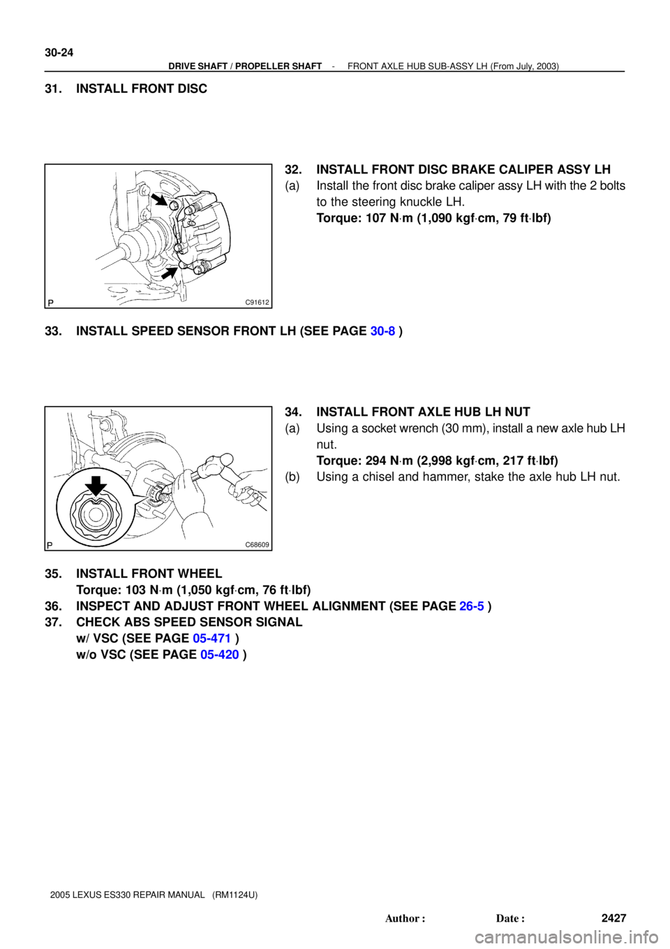
31. INSTALL FRONT DISC
32. INSTALL FRONT DISC BRAKE CALIPER ASSY LH
(a) Install the front disc brake caliper assy LH with the 2 bolts
to the steering knuckle LH.
Torque: 107 NVm (1,090 kgfVcm, 79 ftVlbf)
33. INSTALL SPEED SENSOR FRONT LH (SEE PAGE 30-8)
34. INSTALL FRONT AXLE HUB LH NUT
(a) Using a socket wrench (30 mm), install a new axle hub LH
nut.
Torque: 294 NVm (2,998 kgfVcm, 217 ftVlbf)
(b) Using a chisel and hammer, stake the axle hub LH nut.
35. INSTALL FRONT WHEEL
Torque: 103 NVm (1,050 kgfVcm, 76 ftVlbf)
36. INSPECT AND ADJUST FRONT WHEEL ALIGNMENT (SEE PAGE
26-5)
37. CHECK ABS SPEED SENSOR SIGNAL
w/ VSC (SEE PAGE 05-471)
w/o VSC (SEE PAGE 05-420)
Page 371 of 969
3006I-04
C83014
C83008
C83035
30-26
- DRIVE SHAFT / PROPELLER SHAFTREAR AXLE HUB & BEARING ASSY LH
2429 Author�: Date�:
2005 LEXUS ES330 REPAIR MANUAL (RM1124U)
REAR AXLE HUB & BEARING ASSY LH
REPLACEMENT
HINT:
�COMPONENTS: See page 30-4
�Replace the RH side by the same procedures with the LH side.
1. REMOVE REAR WHEEL
2. DISCONNECT REAR DISC BRAKE CALIPER ASSY LH
(a) Remove the bolt and disconnect the rear flexible hose.
(b) Remove the 2 bolts and rear disc brake caliper assy LH.
(c) Support the rear disc brake caliper assy LH securely.
3. REMOVE REAR DISC
4. DISCONNECT SKID CONTROL SENSOR WIRE
5. REMOVE REAR AXLE HUB & BEARING ASSY LH
(a) Remove the 4 bolts and rear axle hub & bearing assy LH.
6. REMOVE SKID CONTROL SENSOR (SEE PAGE 32-56)
7. INSTALL SKID CONTROL SENSOR (SEE PAGE 32-56)