Page 697 of 969

18-1
2326 Author�: Date�:
2005 LEXUS ES330 REPAIR MANUAL (RM1124U)
IGNITION SYSTEM (3MZ-FE)
ON-VEHICLE INSPECTION
NOTICE:
ºColdº and ºHotº in this se")
1809A-01
- IGNITIONIGNITION SYSTEM (3MZ-FE)
18-1
2326 Author�: Date�:
2005 LEXUS ES330 REPAIR MANUAL (RM1124U)
IGNITION SYSTEM (3MZ-FE)
ON-VEHICLE INSPECTION
NOTICE:
ºColdº and ºHotº in this section mean temperature of the coils themselves. ºColdº is from -10�C
(14�F) to 50�C (122�F) and ºHotº is from 50�C (122�F) to 100�C (212�F).
1. INSPECT IGNITION COIL AND SPARK TEST
(a) Check the DTCs.
NOTICE:
If a DTC is present, perform troubleshooting in accordance with a procedure for that DTC.
(b) Check that a spark occurs.
(1) Remove the 6 ignition coils (see page 18-7).
(2) Using a spark plug wrench 16 mm, remove the 6 spark plugs.
Torque: 25 NVm (250 kgfVcm, 18 ftVlbf)
(3) Install the spark plugs to each ignition coil, then connect the ignition coil connectors.
(4) Disconnect the 6 fuel injector connectors.
(5) Ground the spark plugs.
(6) Check that the spark plug occurs at each spark plug while the engine is being cranked.
NOTICE:
�Be sure to ground the spark plugs when checking.
�Replace the ignition coil if physical impact is felt.
�Do not crank the engine for more than 2 seconds.
If a spark does not occur, perform the following test.
1 SPARK TEST
NG
2 CHECK CONNECTION OF IGNITION COIL CONNECTOR
NG CONNECT SECURELY
OK
3 REPLACE IT WITH NORMAL IGNITION COIL AND PERFORM SPARK TEST AGAIN
OK REPLACE IGNITION COIL ASSY
(See page 18-7)
NG
4 CHECK POWER SUPPLY TO IGNITION COIL
(a) Turn the ignition switch ON.
(b) Check that there is battery voltage at the ignition coil positive (+) terminal.
NG CHECK WIRE HARNESS (BETWEEN IGNITION
(START) SWITCH ASSY AND IGNITION COIL
ASSY)
OK
Page 699 of 969
Spark Plug Gauge
- IGNITIONIGNITION SYSTEM (3MZ-FE)
18-3
2328 Author�: Date�:
2005 LEXUS ES330 REPAIR MANUAL (")
1809B-01
IG0147
Ohmmeter
Ground
B01301
IG0316
B02101
1.0 to 1.1 mm
(0.039 to 0.043 in.)Spark Plug Gauge
- IGNITIONIGNITION SYSTEM (3MZ-FE)
18-3
2328 Author�: Date�:
2005 LEXUS ES330 REPAIR MANUAL (RM1124U)
INSPECTION
1. INSPECT SPARK PLUG
NOTICE:
�Do not use a wire brush to clean the spark plug.
�Do not try to adjust the electrode gap of a used spark
plug.
(a) Inspect the resistance.
(1) Using an ohmmeter, measure the resistance be-
tween the insulation and body ground.
Resistance: 10 MW or more
If the resistance is not as specified, check the electrode gap.
(b) Alternative inspection method.
(1) Quickly accelerate the engine speed to 4,000 rpm
5 times.
(2) Remove the spark plug.
(3) Visually check the spark plug.
(4) If the electrode is dry...OK.
(5) If the electrode is wet...Proceed to step (c).
(6) Reinstall the spark plug.
(c) Check the appearance.
(1) Check the thread and insulator of the spark plug for
damage.
If damaged, replace the spark plug.
Recommended spark plug:
SupplierType
DENSOSK20R11
NGKIFR6A11
(d) Inspect the electrode gap.
(1) Using a spark plug gauge, measure the electrode
gap.
Maximum electrode gap of used spark plug:
1.3 mm (0.051 in.)
If the electrode gap is greater than maximum, replace the spark
plug.
Electrode gap of new spark plug:
1.0 to 1.1 mm (0.039 to 0.043 in.)
Page 701 of 969

(b)
A78529
LH Bank:
(a)
(b)
- IGNITIONVVT SENSOR (3MZ-FE)
18-5
2330 Author�: Date�:
2005 LEXUS ES330 REPAIR MANUAL (RM1124U)
VVT SENSOR (3MZ-FE)
REPLACEMENT
1. DISCONNEC")
1809C-01
A79541
RH Bank:
(a)
(b)
A78529
LH Bank:
(a)
(b)
- IGNITIONVVT SENSOR (3MZ-FE)
18-5
2330 Author�: Date�:
2005 LEXUS ES330 REPAIR MANUAL (RM1124U)
VVT SENSOR (3MZ-FE)
REPLACEMENT
1. DISCONNECT ENGINE WIRE NO. 3 (BATTERY NEGATIVE TERMINAL)
2. REMOVE RADIATOR LOWER AIR DEFLECTOR (See page 19-5)
3. REMOVE AIR CLEANER INLET ASSY (See page 19-5)
4. REMOVE AIR CLEANER ASSY (See page 19-5)
5. REMOVE VVT SENSOR
(a) Remove the 2 VVT sensor connectors.
(b) Remove the 2 bolts, then remove the 2 VVT sensors.
HINT:
The VVT sensor is installed with the bolt.
6. INSTALL VVT SENSOR
(a) Apply a light coat of engine oil to the O-ring on each VVT sensor.
(b) Install the 2 VVT sensors with the 2 bolts.
Torque: 8.0 NVm (80 kgfVcm, 71 in.Vlbf)
NOTICE:
Be careful not to twist the O-ring.
(c) Connect the 2 VVT sensor connectors.
7. INSTALL AIR CLEANER ASSY (See page 19-5)
8. INSTALL AIR CLEANER INLET ASSY (See page 19-5)
9. INSTALL RADIATOR LOWER AIR DEFLECTOR
10. CHECK CONNECTION OF VACUUM HOSE (See page 14-29)
11. CONNECT ENGINE WIRE NO. 3 (BATTERY NEGATIVE TERMINAL)
Torque: 5.4 NVm (55 kgfVcm, 48 in.Vlbf)
12. CHECK FOR ENGINE OIL LEAKS
13. SYSTEM INITIALIZATION (See page 19-15)
Page 703 of 969
(b)
(b)
(b)(a)
(a)
RH Bank:
A86235
(a)
(b)(b)
(b)
(a)
(a)LH Bank:
- IGNITIONIGNITION COIL ASSY (3MZ-FE)
18-7
2332 Author�: Date�:
2005 LEXUS ES330 REPAIR MANUAL (RM1124U)
IGNITION")
1809E-02
A86234
(a)(b)
(b)
(b)(a)
(a)
RH Bank:
A86235
(a)
(b)(b)
(b)
(a)
(a)LH Bank:
- IGNITIONIGNITION COIL ASSY (3MZ-FE)
18-7
2332 Author�: Date�:
2005 LEXUS ES330 REPAIR MANUAL (RM1124U)
IGNITION COIL ASSY (3MZ-FE)
REPLACEMENT
1. DISCONNECT ENGINE WIRE NO. 3 (BATTERY NEGATIVE TERMINAL)
2. DRAIN ENGINE COOLANT (RH BANK) (See page 10-1 1)
3. REMOVE FRONT SUSPENSION UPPER BRACE CENTER (W/O TEMS, RH BANK)
(See page 16-9)
4. REMOVE V-BANK COVER SUB-ASSY (See page 16-9)
5. REMOVE AIR CLEANER CAP SUB-ASSY (RH BANK) (See page 16-9)
6. REMOVE EMISSION CONTROL VALVE SET (RH BANK) (See page 11-13)
7. REMOVE INTAKE AIR SURGE TANK (RH BANK) (See page 11-13)
8. REMOVE IGNITION COIL ASSY
(a) Disconnect the 6 connectors.
(b) Remove the 6 bolts, then remove the 6 ignition coils.
HINT:
The ignition coil is installed with the bolt.
9. INSTALL IGNITION COIL ASSY
Torque: 8.0 NVm (80 kgfVcm, 71 in.Vlbf)
10. INSTALL INTAKE AIR SURGE TANK (RH BANK) (See page 11-13)
11. INSTALL EMISSION CONTROL VALVE SET (RH BANK) (See page 11-13)
12. INSTALL AIR CLEANER CAP SUB-ASSY (RH BANK) (See page 16-9)
13. CHECK CONNECTION OF VACUUM HOSE (RH BANK) (See page 14-29)
14. CONNECT ENGINE WIRE NO. 3 (BATTERY NEGATIVE TERMINAL)
Torque: 5.4 NVm (55 kgfVcm, 48 in.Vlbf)
15. ADD ENGINE COOLANT (RH BANK) (See page 10-1 1)
16. CHECK FOR ENGINE COOLANT LEAKS (RH BANK) (See page 16-1)
17. INSTALL V-BANK COVER SUB-ASSY (See page 16-9)
18. INSTALL FRONT SUSPENSION UPPER BRACE CENTER (W/O TEMS, RH BANK)
(See page 16-9)
19. SYSTEM INITIALIZATION (See page 19-15)
Page 725 of 969
 Visually check the belt for excessive wea")
51018-15
F40449
F40897
Normal
Abnormal
F40898
- POWER STEERINGPOWER STEERING SYSTEM
51-3
2578 Author�: Date�:
ON-VEHICLE INSPECTION
1. INSPECT DRIVE BELT
(a) Visually check the belt for excessive wear, frayed cords,
etc.
If any defect is found, replace the drive belt.
HINT:
Cracks on the rib side of a belt are considered acceptable. If the
missing chunks from the ribs are found on the belt, it should be
replaced.
2. BLEED POWER STEERING SYSTEM
(a) Check the fluid level.
(b) Jack up the front of the vehicle and support it with the
stands.
(c) Turn the steering wheel.
(1) With the engine stopped, turn the wheel slowly from
lock to lock several times.
(d) Lower the vehicle.
(e) Start the engine.
(1) Run the engine at idle for a few minutes.
(f) Turn the steering wheel.
(1) With the engine idling, turn the wheel to left or right
full lock position and keep it there for 2 - 3 seconds,
then turn the wheel to the opposite full lock position
and keep it there for 2 - 3 seconds.
(2) Repeat (1) several times.
(g) Stop the engine.
(h) Check for forming or emulsification.
Especially, if the system has to be bled twice because of foam-
ing or emulsification, check for fluid leaks in the system.
(i) Check the fluid level.
3. CHECK FLUID LEVEL
(a) Keep the vehicle level.
(b) With the engine stopped, check the fluid level in the oil
reservoir.
If necessary, add fluid.
Fluid: ATF DEXRON® II or III
HINT:
Check that the fluid level is within the HOT LEVEL range on the
reservoir cap. If the fluid is cold, check that it is within the COLD
LEVEL range.
Page 726 of 969

or less 51-4
- POWER STEERINGPOWER STEERING SYSTEM
2579 Author�: Date�:
(c) Start the engine and run it at idle.
(d) Turn the st")
F40897
NormalAbnormal
R11786Engine Idling Engine Stopped5 mm (0.20 in.)
or less 51-4
- POWER STEERINGPOWER STEERING SYSTEM
2579 Author�: Date�:
(c) Start the engine and run it at idle.
(d) Turn the steering wheel from lock to lock several times to
raise fluid temperature.
Fluid temperature: 75 - 80°C (167 - 176°F)
(e) Check for foaming or emulsification.
If foaming or emulsification is identified, bleed the power steer-
ing system.
(f) With the engine idling, measure the fluid level in the oil
reservoir.
(g) Stop the engine.
(h) Wait a few minutes and remeasure the fluid level in the oil
reservoir.
Maximum fluid level rise: 5 mm (0.20 in.)
If a problem is found, bleed the power steering system.
(i) Check the fluid level.
4. CHECK STEERING FLUID PRESSURE
(a) Disconnect the pressure feed tube assy from the rack &
pinion power steering gear assy (See page 51-21).
(b) Connect SST, as shown in the illustration.
SST 09640-10010 (09641-01010, 09641-01020,
09641-01030)
NOTICE:
Check that the valve of the SST is in the open position.
(c) Bleed the power steering system.
(d) Start the engine and run it at idle.
(e) Turn the steering wheel from lock to lock several times to
raise fluid temperature.
Fluid temperature: 75 - 80 °C (167 - 176 °F)
Page 728 of 969
F41590
51-6
- POWER STEERINGPOWER STEERING SYSTEM
2581 Author�: Date�:
(j) Disconnect the SST.
SST 09640- 10010 (09641- 01010, 09641- 01020,
09641-01030)
(k) Connect the pressure feed tube assy to the rack & pinion
power steering gear assy (See page 51-21).
(l) Bleed the power steering system.
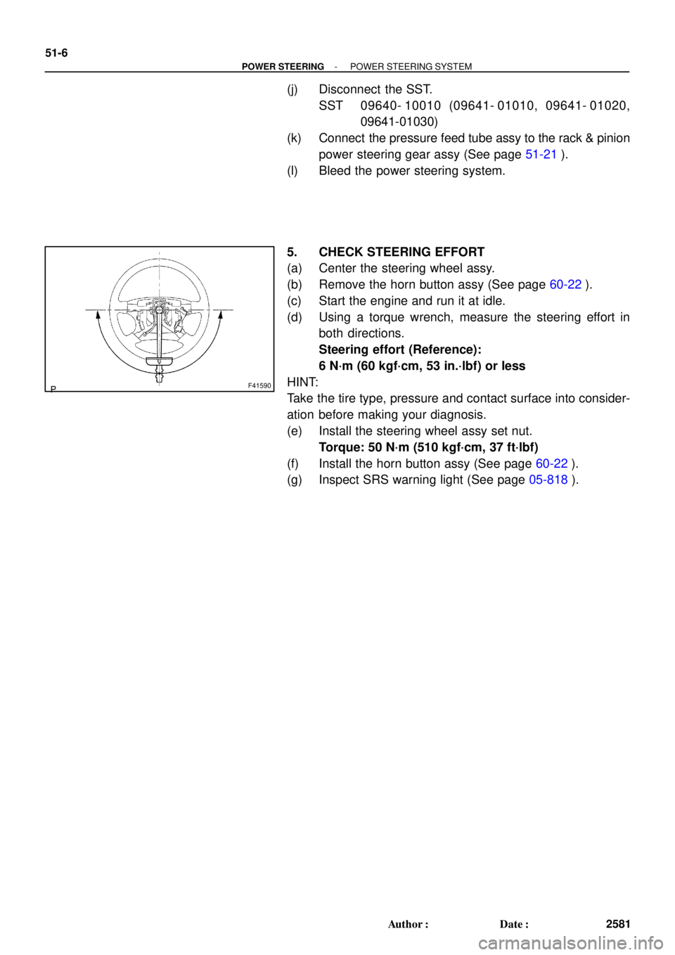
5. CHECK STEERING EFFORT
(a) Center the steering wheel assy.
(b) Remove the horn button assy (See page 60-22).
(c) Start the engine and run it at idle.
(d) Using a torque wrench, measure the steering effort in
both directions.
Steering effort (Reference):
6 N´m (60 kgf´cm, 53 in.´lbf) or less
HINT:
Take the tire type, pressure and contact surface into consider-
ation before making your diagnosis.
(e) Install the steering wheel assy set nut.
Torque: 50 N´m (510 kgf´cm, 37 ft´lbf)
(f) Install the horn button assy (See page 60-22).
(g) Inspect SRS warning light (See page 05-818).
Page 796 of 969
190SI-01
- STARTING & CHARGINGCHARGING SYSTEM (3MZ-FE)
19-15
2347 Author�: Date�:
2005 LEXUS ES330 REPAIR MANUAL (RM1124U)
CHARGING SYSTEM (3MZ-FE)
PRECAUTION
1. SYSTEM INITIALIZATION
NOTICE:
When disconnecting the negative (-) battery terminal, initialize the following systems after the termi-
nal is reconnected.
System NameSee Page
Power Window Control System05-1470
Sliding Roof System74-8
2. Check that the battery cables are connected to the correct terminals.
3. Disconnect the battery cables if a quick charge is given to the battery.
4. Do not perform tests with a high voltage insulation resistance tester.
5. Never disconnect the battery while the engine is running.
6. Check that the charging cable is tightened on terminal B of the generator and the fuse box.
7. Do not check whether the alternator generates current or not with terminal F connected to the
other terminals.