2005 LEXUS ES300 check engine
[x] Cancel search: check enginePage 869 of 969
RADIATOR CAP INSPECTION ± EG007-05 March 28, 2005
Page 4 of 7
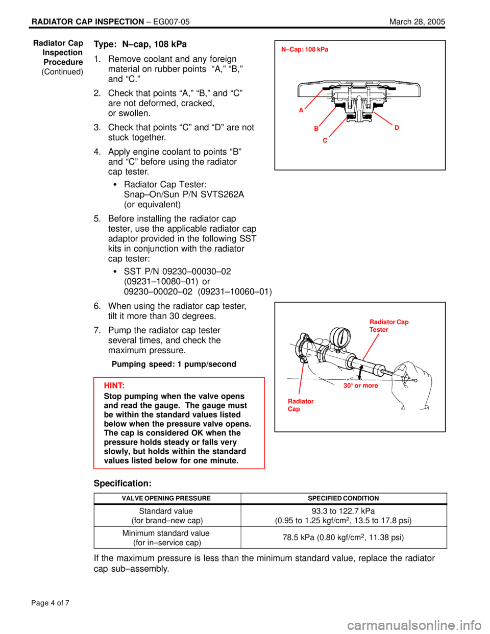
Type: N±cap, 108 kPa
1. Remove coolant and any foreign
material on rubber points ªA,º ªB,º
and ªC.º
2. Check that points ªA,º ªB,º and ªCº
are not deformed, cracked,
or swollen.
3. Check that points ªCº and ªDº are not
stuck together.
4. Apply engine coolant to points ªBº
and ªCº before using the radiator
cap tester.
�Radiator Cap Tester:
Snap±On/Sun P/N SVTS262A
(or equivalent)
5. Before installing the radiator cap
tester, use the applicable radiator cap
adaptor provided in the following SST
kits in conjunction with the radiator
cap tester:
�SST P/N 09230±00030±02
(09231±10080±01) or
09230±00020±02 (09231±10060±01)
6. When using the radiator cap tester,
tilt it more than 30 degrees.
7. Pump the radiator cap tester
several times, and check the
maximum pressure.
Pumping speed: 1 pump/second
HINT:
Stop pumping when the valve opens
and read the gauge. The gauge must
be within the standard values listed
below when the pressure valve opens.
The cap is considered OK when the
pressure holds steady or falls very
slowly, but holds within the standard
values listed below for one minute.
Specification:
VALVE OPENING PRESSURESPECIFIED CONDITION
Standard value
(for brand±new cap)93.3 to 122.7 kPa
(0.95 to 1.25 kgf/cm2, 13.5 to 17.8 psi)
Minimum standard value
(for in±service cap)78.5 kPa (0.80 kgf/cm2, 11.38 psi)
If the maximum pressure is less than the minimum standard value, replace the radiator
cap sub±assembly.
Radiator Cap
Inspection
Procedure
(Continued)
A
C BD N±Cap: 108 kPa
Radiator Cap
Tester
305 or more
Radiator
Cap
Page 870 of 969
RADIATOR CAP INSPECTION ± EG007-05 March 28, 2005
Page 5 of 7
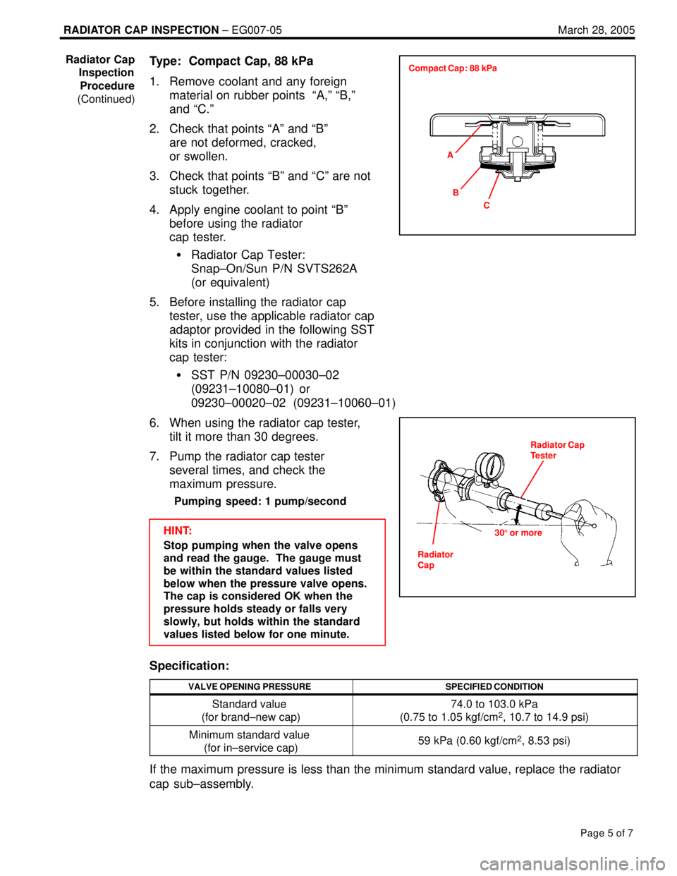
Type: Compact Cap, 88 kPa
1. Remove coolant and any foreign
material on rubber points ªA,º ªB,º
and ªC.º
2. Check that points ªAº and ªBº
are not deformed, cracked,
or swollen.
3. Check that points ªBº and ªCº are not
stuck together.
4. Apply engine coolant to point ªBº
before using the radiator
cap tester.
�Radiator Cap Tester:
Snap±On/Sun P/N SVTS262A
(or equivalent)
5. Before installing the radiator cap
tester, use the applicable radiator cap
adaptor provided in the following SST
kits in conjunction with the radiator
cap tester:
�SST P/N 09230±00030±02
(09231±10080±01) or
09230±00020±02 (09231±10060±01)
6. When using the radiator cap tester,
tilt it more than 30 degrees.
7. Pump the radiator cap tester
several times, and check the
maximum pressure.
Pumping speed: 1 pump/second
HINT:
Stop pumping when the valve opens
and read the gauge. The gauge must
be within the standard values listed
below when the pressure valve opens.
The cap is considered OK when the
pressure holds steady or falls very
slowly, but holds within the standard
values listed below for one minute.
Specification:
VALVE OPENING PRESSURESPECIFIED CONDITION
Standard value
(for brand±new cap)74.0 to 103.0 kPa
(0.75 to 1.05 kgf/cm2, 10.7 to 14.9 psi)
Minimum standard value
(for in±service cap)59 kPa (0.60 kgf/cm2, 8.53 psi)
If the maximum pressure is less than the minimum standard value, replace the radiator
cap sub±assembly.
Radiator Cap
Inspection
Procedure
(Continued)
A
C B Compact Cap: 88 kPa
Radiator Cap
Tester
305 or more
Radiator
Cap
Page 871 of 969
RADIATOR CAP INSPECTION ± EG007-05 March 28, 2005
Page 6 of 7
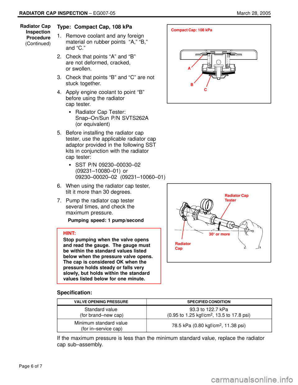
Type: Compact Cap, 108 kPa
1. Remove coolant and any foreign
material on rubber points ªA,º ªB,º
and ªC.º
2. Check that points ªAº and ªBº
are not deformed, cracked,
or swollen.
3. Check that points ªBº and ªCº are not
stuck together.
4. Apply engine coolant to point ªBº
before using the radiator
cap tester.
�Radiator Cap Tester:
Snap±On/Sun P/N SVTS262A
(or equivalent)
5. Before installing the radiator cap
tester, use the applicable radiator cap
adaptor provided in the following SST
kits in conjunction with the radiator
cap tester:
�SST P/N 09230±00030±02
(09231±10080±01) or
09230±00020±02 (09231±10060±01)
6. When using the radiator cap tester,
tilt it more than 30 degrees.
7. Pump the radiator cap tester
several times, and check the
maximum pressure.
Pumping speed: 1 pump/second
HINT:
Stop pumping when the valve opens
and read the gauge. The gauge must
be within the standard values listed
below when the pressure valve opens.
The cap is considered OK when the
pressure holds steady or falls very
slowly, but holds within the standard
values listed below for one minute.
Specification:
VALVE OPENING PRESSURESPECIFIED CONDITION
Standard value
(for brand±new cap)93.3 to 122.7 kPa
(0.95 to 1.25 kgf/cm2, 13.5 to 17.8 psi)
Minimum standard value
(for in±service cap)78.5 kPa (0.80 kgf/cm2, 11.38 psi)
If the maximum pressure is less than the minimum standard value, replace the radiator
cap sub±assembly.
Radiator Cap
Inspection
Procedure
(Continued)
A
C B Compact Cap: 108 kPa
Radiator Cap
Tester
305 or more
Radiator
Cap
Page 872 of 969
RADIATOR CAP INSPECTION ± EG007-05 March 28, 2005
Page 7 of 7
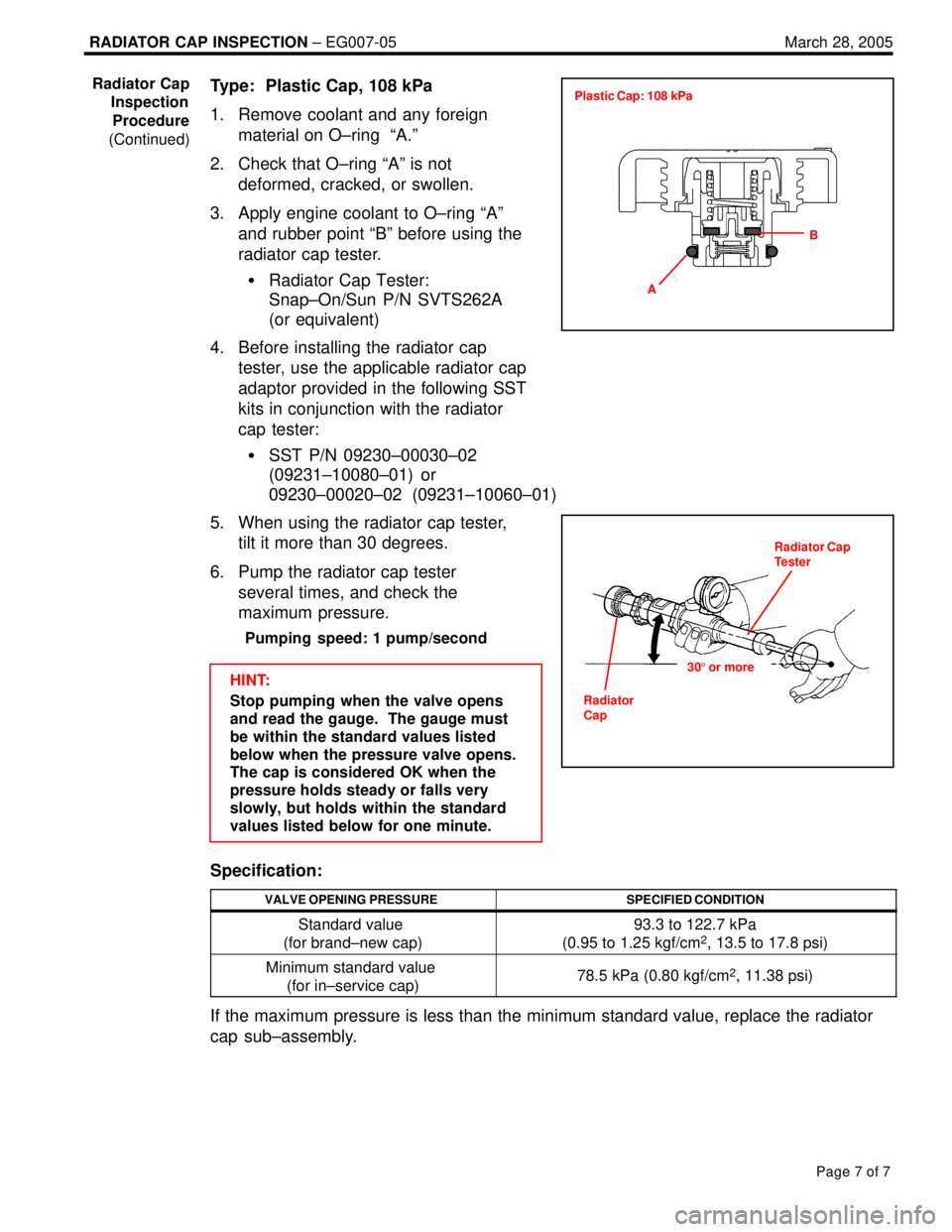
Type: Plastic Cap, 108 kPa
1. Remove coolant and any foreign
material on O±ring ªA.º
2. Check that O±ring ªAº is not
deformed, cracked, or swollen.
3. Apply engine coolant to O±ring ªAº
and rubber point ªBº before using the
radiator cap tester.
�Radiator Cap Tester:
Snap±On/Sun P/N SVTS262A
(or equivalent)
4. Before installing the radiator cap
tester, use the applicable radiator cap
adaptor provided in the following SST
kits in conjunction with the radiator
cap tester:
�SST P/N 09230±00030±02
(09231±10080±01) or
09230±00020±02 (09231±10060±01)
5. When using the radiator cap tester,
tilt it more than 30 degrees.
6. Pump the radiator cap tester
several times, and check the
maximum pressure.
Pumping speed: 1 pump/second
HINT:
Stop pumping when the valve opens
and read the gauge. The gauge must
be within the standard values listed
below when the pressure valve opens.
The cap is considered OK when the
pressure holds steady or falls very
slowly, but holds within the standard
values listed below for one minute.
Specification:
VALVE OPENING PRESSURESPECIFIED CONDITION
Standard value
(for brand±new cap)93.3 to 122.7 kPa
(0.95 to 1.25 kgf/cm2, 13.5 to 17.8 psi)
Minimum standard value
(for in±service cap)78.5 kPa (0.80 kgf/cm2, 11.38 psi)
If the maximum pressure is less than the minimum standard value, replace the radiator
cap sub±assembly.
Radiator Cap
Inspection
Procedure
(Continued)
A
B Plastic Cap: 108 kPa
Radiator Cap
Tester
305 or more
Radiator
Cap
Page 895 of 969

PRE±DELIVERY SERVICE (PDS) INFORMATION FOR ES 330 ± PD002-03 August 26, 2003
Page 8 of 9
INITIAL CALIBRATION OF COMPASS (Continued)
3. Check that the direction appears
several seconds after adjustment.
4. Start the engine and push the switch
for about 6 seconds until ªCº appears
on the display.
5. Drive the vehicle slowly at 5 mph, or
less, in a circle until the direction is
displayed. If there is not enough space
to drive in a circle, drive around the
block until the direction is displayed.
After driving in circles 1 to 3 times,
calibration is complete with the direction
shown on the display.
NOTE:
�Do not perform calibration of the compass in a place where the earth's magnetic
field is subject to interference by artificial magnetic fields (underground parking,
under a steel tower, between buildings, roof parking, near a railroad crossing, near
a large vehicle, etc.)
�During calibration, do not operate electric systems (moon roof, power windows,
etc.) as they may interfere with the calibration.
ITEM NO. 5:
Compass
Calibration
Procedure
(Continued)
Page 902 of 969

INITIAL CALIBRATION OF COMPASS DURING PDS ± PD034-05 August 22, 2005
Page 3 of 3
3. Check that the direction appears
several seconds after adjustment.
4. Start the engine and push the switch
for about 6 seconds until ªCº appears
on the display.
5. Drive the vehicle slowly at 5 mph
(8 km/h), or less, in a circle until the
direction is displayed. If there is not
enough space to drive in a circle,
drive around the block until the
direction is displayed.
After driving in 1 to 3 circles,
calibration is complete with the
direction shown on the display.
NOTE:
�Do NOT perform calibration of the compass in a place where the Earth's magnetic
field is subject to interference by artificial magnetic fields (underground parking,
under a steel tower, between buildings, roof parking, near a railroad crossing, near
a large vehicle, etc.)
�During calibration, do NOT operate electric systems (moon roof, power windows,
etc.) as they may interfere with the calibration. Compass
Calibration
Procedure
(Continued)
Page 914 of 969
Lexus Supports ASE CertificationPage 1 of 4
Title:
BATTERY MAINTENANCE FOR
IN-STOCK VEHICLES & PRE-DELIVERY
Models:
All Models & Model Years Through Current
Technical Service
Information Bulletin
September 12, 2002
PG009-02
A battery in a stored vehicle is subject to conditions that can reduce its performance and
life. These conditions include storage period, temperature, parasitic drain, and battery
load. Because of these factors, battery inspection and maintenance are required in
order to ensure proper operation and optimal battery life.
As a matter of policy, Lexus does not provide battery warranty coverage for discharged
and/or failed batteries due to lack of maintenance; it is the dealer's responsibility to
maintain the specified state of charge of the vehicle's battery while in stock and assure
proper state of charge at delivery.
To eliminate customer service concerns due to an undercharged battery during the first
few weeks of ownership, all dealers should check battery state of charge and
recharge, if necessary, just prior to delivery (i.e., within 48 hours of delivery).
This new procedure will improve the new vehicle ownership experience by greatly
reducing the risk of having a low performance battery concern due to extended storage
periods and/or short engine run times prior to the vehicle sale.
�All models and model years through current.
SPECIAL SERVICE TOOLS (SSTs)MANUFACTURERPART NUMBER
MICROPRO 815 Digital
Battery Analyzer
(Essential SST)*Midtronics00002±MP815±T
* This SST can be ordered through SPX/OTC by calling 1±800±933±8335.
NOTE:
MICROPRO 815 Digital Battery Analyzer should be periodically updated through the
Technical Information System (TIS) for new vehicle models. For detailed information,
please see TSIB SS002±02, ªMidtronics Battery Tester Software Update.º
OP CODEDESCRIPTIONTIMEOFPT1T2
N/ANot Applicable to Warranty±±±±
PRODUCT GENERAL INFORMATION
Introduction
Applicable
Vehicles
Required
Tools &
Material
Warranty
Information
Page 926 of 969
August 26, 2002IMMOBILIZER KEY CODE RESET ± SS002-01 Revised
Page 3 of 6
NOTE:
Ensure that the Diagnostic Tester is equipped with the latest version of software (13.0a
or later).
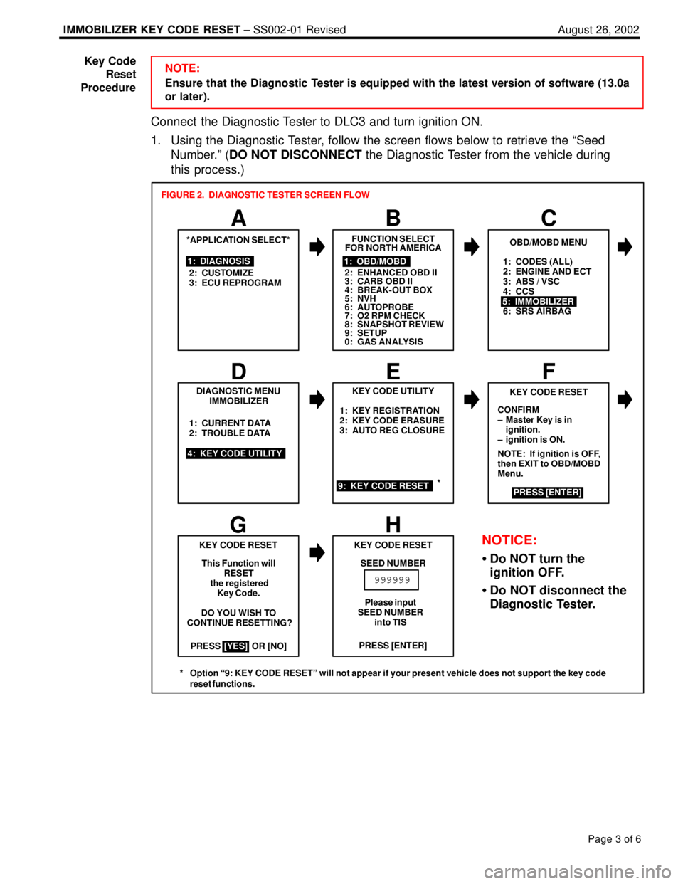
Connect the Diagnostic Tester to DLC3 and turn ignition ON.
1. Using the Diagnostic Tester, follow the screen flows below to retrieve the ªSeed
Number.º (DO NOT DISCONNECT the Diagnostic Tester from the vehicle during
this process.)
1: CODES (ALL)
2: ENGINE AND ECT
3: ABS / VSC
4: CCS
6: SRS AIRBAG
PRESS OR [NO]1: KEY REGISTRATION
2: KEY CODE ERASURE
3: AUTO REG CLOSURE
*APPLICATION SELECT*
1: DIAGNOSIS
2: CUSTOMIZE
3: ECU REPROGRAM
A
FUNCTION SELECT
FOR NORTH AMERICA
BC
1: OBD/MOBD
2: ENHANCED OBD II
3: CARB OBD II
4: BREAK-OUT BOX
5: NVH
6: AUTOPROBE
7: O2 RPM CHECK
8: SNAPSHOT REVIEW
9: SETUP
0: GAS ANALYSIS
OBD/MOBD MENU
5: IMMOBILIZER
DIAGNOSTIC MENU
IMMOBILIZER
4: KEY CODE UTILITY1: CURRENT DATA
2: TROUBLE DATA
D
KEY CODE UTILITY
EF
9: KEY CODE RESET
KEY CODE RESET
CONFIRM
± Master Key is in
ignition.
± ignition is ON.
NOTE: If ignition is OFF,
then EXIT to OBD/MOBD
Menu.
PRESS [ENTER]
GH
KEY CODE RESET
This Function will
RESET
the registered
Key Code.
DO YOU WISH TO
CONTINUE RESETTING?
[YES]PRESS [ENTER] KEY CODE RESET
SEED NUMBER
999999
FIGURE 2. DIAGNOSTIC TESTER SCREEN FLOW
Please input
SEED NUMBER
into TIS
NOTICE:
�Do NOT turn the
ignition OFF.
�Do NOT disconnect the
Diagnostic Tester.
*
* Option ª9: KEY CODE RESETº will not appear if your present vehicle does not support the key code
reset functions.
Key Code
Reset
Procedure