Page 663 of 969
16-14
- COOLINGWATER PUMP ASSY (3MZ-FE)
2292 Author�: Date�:
2005 LEXUS ES330 REPAIR MANUAL (RM1124U)
27. INSTALL TIMING BELT TENSIONER ASSY (See page 14-79)
28. INSTALL TIMING BELT GUIDE NO.2 (See page 14-79)
29. INSTALL ENGINE MOUNTING BRACKET RH (See page 14-79)
30. INSTALL TIMING BELT NO.2 COVER (See page 14-79)
31. INSTALL TIMING BELT NO.1 COVER (See page 14-79)
32. INSTALL CRANKSHAFT PULLEY (See page 14-79)
SST 09213-54015 (91651-60855), 09330-00021
33. INSTALL GENERATOR BRACKET NO.2 (See page 14-79)
34. INSTALL ENGINE MOUNTING STAY NO.2 RH (See page 14-79)
35. INSTALL ENGINE MOVING CONTROL ROD (See page 14-79)
36. INSTALL VANE PUMP V BELT (See page 14-5)
37. INSTALL V (COOLER COMPRESSOR TO CRANKSHAFT PULLEY) BELT NO.1
(See page 14-5)
38. INSPECT DRIVE BELT DEFLECTION AND TENSION (See page 14-1)
39. INSTALL FRONT WHEEL RH (See page 14-5)
40. ADD ENGINE COOLANT (See page 16-9)
41. CHECK FOR ENGINE COOLANT LEAKS (See page 16-1)
Page 666 of 969
- COOLINGTHERMOSTAT (3MZ-FE)
16-17
2295 Author�: Date�:
2005 LEXUS ES330 REPAIR MANUAL (RM1124U)
11. INSTALL WATER INLET PIPE
(a) Install a new O-ring to the water inlet pipe.
(b) Apply soapy water to the O-ring.
(c) Connect the water inlet pipe to the water inlet.
(d) Install the bolt which is used to fixes the water inlet pipe to the cylinder head.
Torque: 20 NVm (199 kgfVcm,
14 ftVlbf)
12. INSTALL AIR CLEANER ASSY (See page 19-5)
13. INSTALL AIR CLEANER INLET ASSY (See page 19-5)
14. CHECK CONNECTION OF VACUUM HOSE (See page 14-29)
15. ADD ENGINE COOLANT (See page 16-9)
16. CHECK FOR ENGINE COOLANT LEAKS (See page 16-1)
Page 671 of 969

A86562
A86563
16-22
- COOLINGRADIATOR ASSY (3MZ-FE)
2300 Author�: Date�:
2005 LEXUS ES330 REPAIR MANUAL (RM1124U)
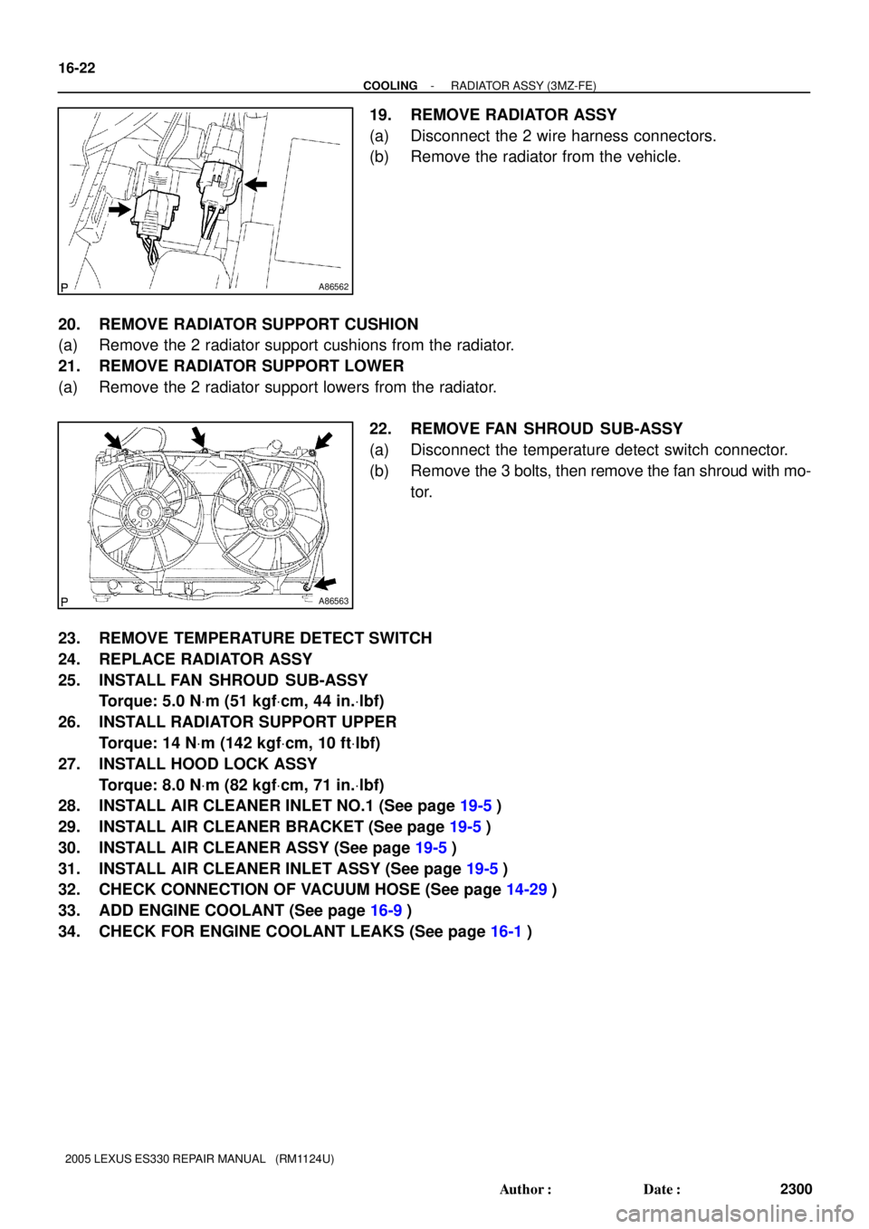
19. REMOVE RADIATOR ASSY
(a) Disconnect the 2 wire harness connectors.
(b) Remove the radiator from the vehicle.
20. REMOVE RADIATOR SUPPORT CUSHION
(a) Remove the 2 radiator support cushions from the radiator.
21. REMOVE RADIATOR SUPPORT LOWER
(a) Remove the 2 radiator support lowers from the radiator.
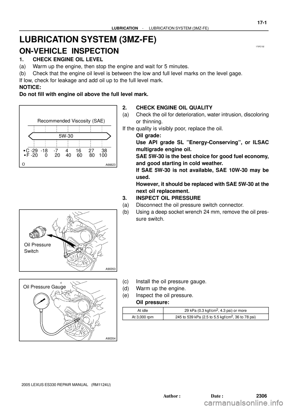
22. REMOVE FAN SHROUD SUB-ASSY
(a) Disconnect the temperature detect switch connector.
(b) Remove the 3 bolts, then remove the fan shroud with mo-
tor.
23. REMOVE TEMPERATURE DETECT SWITCH
24. REPLACE RADIATOR ASSY
25. INSTALL FAN SHROUD SUB-ASSY
Torque: 5.0 NVm (51 kgfVcm, 44 in.Vlbf)
26. INSTALL RADIATOR SUPPORT UPPER
Torque: 14 NVm (142 kgfVcm, 10 ftVlbf)
27. INSTALL HOOD LOCK ASSY
Torque: 8.0 NVm (82 kgfVcm, 71 in.Vlbf)
28. INSTALL AIR CLEANER INLET NO.1 (See page 19-5)
29. INSTALL AIR CLEANER BRACKET (See page 19-5)
30. INSTALL AIR CLEANER ASSY (See page 19-5)
31. INSTALL AIR CLEANER INLET ASSY (See page 19-5)
32. CHECK CONNECTION OF VACUUM HOSE (See page 14-29)
33. ADD ENGINE COOLANT (See page 16-9)
34. CHECK FOR ENGINE COOLANT LEAKS (See page 16-1)
Page 677 of 969

170FZ-02
A66623
�C -29 -18 -7 4 16 27 38Recommended Viscosity (SAE)
�F -20 0 20 40 60 80 1005W-30
A90353
Oil Pressure
Switch
A90354
Oil Pressure Gauge
- LUBRICATIONLUBRICATION SYSTEM (3MZ-FE)
17-1
2306 Author�: Date�:
2005 LEXUS ES330 REPAIR MANUAL (RM1124U)
LUBRICATION SYSTEM (3MZ-FE)
ON-VEHICLE INSPECTION
1. CHECK ENGINE OIL LEVEL
(a) Warm up the engine, then stop the engine and wait for 5 minutes.
(b) Check that the engine oil level is between the low and full level marks on the level gage.
If low, check for leakage and add oil up to the full level mark.
NOTICE:
Do not fill with engine oil above the full level mark.
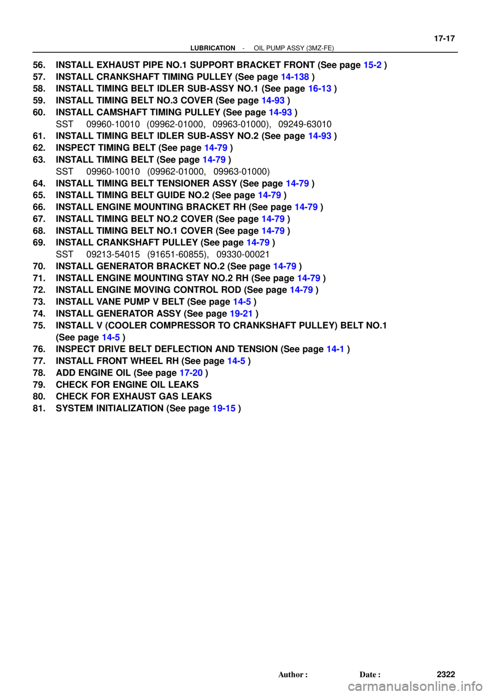
2. CHECK ENGINE OIL QUALITY
(a) Check the oil for deterioration, water intrusion, discoloring
or thinning.
If the quality is visibly poor, replace the oil.
Oil grade:
Use API grade SL ºEnergy-Conservingº, or ILSAC
multigrade engine oil.
SAE 5W-30 is the best choice for good fuel economy,
and good starting in cold weather.
If SAE 5W-30 is not available, SAE 10W-30 may be
used.
However, it should be replaced with SAE 5W-30 at the
next oil replacement.
3. INSPECT OIL PRESSURE
(a) Disconnect the oil pressure switch connector.
(b) Using a deep socket wrench 24 mm, remove the oil pres-
sure switch.
(c) Install the oil pressure gauge.
(d) Warm up the engine.
(e) Inspect the oil pressure.
Oil pressure:
At idle29 kPa (0.3 kgf/cm2, 4.3 psi) or more
At 3,000 rpm245 to 539 kPa (2.5 to 5.5 kgf/cm2, 36 to 78 psi)
Page 678 of 969
A85603
Adhesive 17-2
- LUBRICATIONLUBRICATION SYSTEM (3MZ-FE)
2307 Author�: Date�:
2005 LEXUS ES330 REPAIR MANUAL (RM1124U)
(f) Apply adhesive to 2 or 3 threads of the oil pressure switch.
Adhesive:
Part No. 08833-00080, THREE BOND 1344,
LOCTITE 242 or equivalent
(g) Using a deep socket wrench 24 mm, install the oil pres-
sure switch.
Torque: 15 NVm (153 kgfVcm, 11 ftVlbf)
NOTICE:
Do not start the engine within 1 hour of installation.
(h) Connect the oil pressure switch connector.
(i) Check for the engine oil leaks.
Page 693 of 969

- LUBRICATIONOIL PUMP ASSY (3MZ-FE)
17-17
2322 Author�: Date�:
56. INSTALL EXHAUST PIPE NO.1 SUPPORT BRACKET FRONT (See page 15-2)
57. INSTALL CRANKSHAFT TIMING PULLEY (See page 14-138)
58. INSTALL TIMING BELT IDLER SUB-ASSY NO.1 (See page 16-13)
59. INSTALL TIMING BELT NO.3 COVER (See page 14-93)
60. INSTALL CAMSHAFT TIMING PULLEY (See page 14-93)
SST 09960-10010 (09962-01000, 09963-01000), 09249-63010
61. INSTALL TIMING BELT IDLER SUB-ASSY NO.2 (See page 14-93)
62. INSPECT TIMING BELT (See page 14-79)
63. INSTALL TIMING BELT (See page 14-79)
SST 09960-10010 (09962-01000, 09963-01000)
64. INSTALL TIMING BELT TENSIONER ASSY (See page 14-79)
65. INSTALL TIMING BELT GUIDE NO.2 (See page 14-79)
66. INSTALL ENGINE MOUNTING BRACKET RH (See page 14-79)
67. INSTALL TIMING BELT NO.2 COVER (See page 14-79)
68. INSTALL TIMING BELT NO.1 COVER (See page 14-79)
69. INSTALL CRANKSHAFT PULLEY (See page 14-79)
SST 09213-54015 (91651-60855), 09330-00021
70. INSTALL GENERATOR BRACKET NO.2 (See page 14-79)
71. INSTALL ENGINE MOUNTING STAY NO.2 RH (See page 14-79)
72. INSTALL ENGINE MOVING CONTROL ROD (See page 14-79)
73. INSTALL VANE PUMP V BELT (See page 14-5)
74. INSTALL GENERATOR ASSY (See page 19-21)
75. INSTALL V (COOLER COMPRESSOR TO CRANKSHAFT PULLEY) BELT NO.1
(See page 14-5)
76. INSPECT DRIVE BELT DEFLECTION AND TENSION (See page 14-1)
77. INSTALL FRONT WHEEL RH (See page 14-5)
78. ADD ENGINE OIL (See page 17-20)
79. CHECK FOR ENGINE OIL LEAKS
80. CHECK FOR EXHAUST GAS LEAKS
81. SYSTEM INITIALIZATION (See page 19-15)
Page 694 of 969

170F4-03
A33002
A33003
A33004
A33005
17-18
- LUBRICATIONOIL PUMP ASSY (3MZ-FE)
2323 Author�: Date�:
2005 LEXUS ES330 REPAIR MANUAL (RM1124U)
OVERHAUL
1. REMOVE OIL PUMP RELIEF VALVE
(a) Remove the plug, spring and relief valve.
2. INSPECT OIL PUMP RELIEF VALVE
(a) Apply a light coat of engine oil to the relief valve.
(b) Check that the relief valve falls smoothly into the valve
hole by its own weight.
3. INSPECT OIL PUMP ASSY
(a) Remove the oil pump cover.
(1) Remove the 10 screws and oil pump cover.
(b) Remove the oil pump rotor set.
NOTICE:
Do not change the combination or turn over the 2 removed
rotors.
(c) Inspect the oil pump rotor set.
(1) Apply a light coat of engine oil to the oil pump rotor
set, then place them into the oil pump body. Check
that the rotors revolve smoothly.
(d) Inspect the tip clearance.
(1) Using a feeler gauge, measure the clearance be-
tween the drive and driven rotor tips.
Standard tip clearance:
0.06 to 0.18 mm (0.0024 to 0.0071 in.)
Maximum tip clearance: 0.35 mm (0.0138 in.)
(e) Inspect the body clearance.
(1) Using a feeler gauge, measure the clearance be-
tween the driven rotor and body.
Standard body clearance:
0.250 to 0.325 mm (0.0098 to 0.0128 in.)
Maximum body clearance: 0.30 mm (0.0118 in.)
(f) Inspect the side clearance.
(1) Using a feeler gauge and precision straight edge,
measure the clearance between the rotors and pre-
cision straight edge.
Standard side clearance:
0.03 to 0.09 mm (0.0012 to 0.0035 in.)
Maximum side clearance: 0.15 mm (0.0059 in.)
Page 696 of 969

170F5-03
A78720
SST
P12582
Additional
3/4 TurnSST
17-20
- LUBRICATIONOIL FILTER SUB-ASSY (3MZ-FE)
2325 Author�: Date�:
2005 LEXUS ES330 REPAIR MANUAL (RM1124U)
OIL FILTER SUB-ASSY (3MZ-FE)
REPLACEMENT
CAUTION:
�Prolonged and repeated contact with engine oil will cause removal of natural oils from the skin,
leading to dryness, irritation and dermatitis. In addition, used engine oil contains potentially
harmful contaminants which may cause skin cancer.
�Precautions should be taken when replacing engine oil to minimize the risk of your skin making
contact with used engine oil. Wear protective clothing and gloves. Wash your skin thoroughly
with soap and water, or use water-less hand cleaner to remove any used engine oil. Do not use
gasoline, thinners, or solvents.
�For environmental protection used oil and used oil filter must be disposed of at designated dis-
posal sites.
1. REMOVE ENGINE UNDER COVER NO.1
2. DRAIN ENGINE OIL
(a) Remove the oil filler cap.
(b) Remove the oil drain plug, then drain the oil into a container.
(c) Clean and install the oil drain plug with a new gasket.
Torque: 45 NVm (459 kgfVcm,
33 ftVlbf)
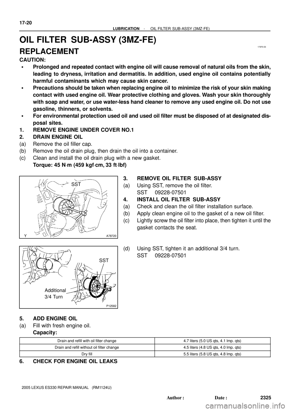
3. REMOVE OIL FILTER SUB-ASSY
(a) Using SST, remove the oil filter.
SST 09228-07501
4. INSTALL OIL FILTER SUB-ASSY
(a) Check and clean the oil filter installation surface.
(b) Apply clean engine oil to the gasket of a new oil filter.
(c) Lightly screw the oil filter into place, then tighten it until the
gasket contacts the seat.
(d) Using SST, tighten it an additional 3/4 turn.
SST 09228-07501
5. ADD ENGINE OIL
(a) Fill with fresh engine oil.
Capacity:
Drain and refill with oil filter change4.7 liters (5.0 US qts, 4.1 lmp. qts)
Drain and refill without oil filter change4.5 liters (4.8 US qts, 4.0 lmp. qts)
Dry fill5.5 liters (5.8 US qts, 4.8 lmp. qts)
6. CHECK FOR ENGINE OIL LEAKS