Page 618 of 969

12-5
2066 Author�: Date�:
2005 LEXUS ES330 REPAIR MANUAL (RM1124U)
(d) If you have no hand-")
A86348Battery
A59500
Vacuum Gauge
A72589
Pressure Gauge
- EMISSION CONTROLEMISSION CONTROL SYSTEM (3MZ-FE)
12-5
2066 Author�: Date�:
2005 LEXUS ES330 REPAIR MANUAL (RM1124U)
(d) If you have no hand-held tester:
Force the VSV for EVAP to operate.
(1) Disconnect the VSV for EVAP connector.
(2) Connect the positive (+) and negative (-) leads of
the battery to the VSV for EVAP terminals.
(3) Start the engine.
(e) Check the vacuum at idle.
Vacuum:
Maintain at 0.368 to 19.713 in.Hg (5 to 268 in.Aq) for
over 5 seconds.
HINT:
If the vacuum does not change, it can be concluded that the
hose which connects the VSV to the service port is loose or
blocked, or the VSV is malfunctioning.
(f) If you have the hand-held tester:
Return to the normal VSV for EVAP.
(1) Stop the engine.
(2) Disconnect the hand-held tester from the DLC3.
(g) If you have no hand-held tester:
Return to the normal VSV for EVAP.
(1) Stop the engine.
(2) Disconnect the positive (+) and negative (-) leads
of the battery from the VSV for EVAP terminals.
(3) Reconnect the VSV for EVAP connector.
(h) Disconnect the vacuum gauge from the EVAP service
port on the purge line.
(i) Connect a pressure gauge to the EVAP service port on
the purge line.
Page 619 of 969

2067 Author�: Date�:
2005 LEXUS ES3")
A86347DLC3
Hand-held Tester
A86349Battery
A59501
Pressure Gauge
Pressure
A52634
Fuel Tank CapPressure Gauge
12-6
- EMISSION CONTROLEMISSION CONTROL SYSTEM (3MZ-FE)
2067 Author�: Date�:
2005 LEXUS ES330 REPAIR MANUAL (RM1124U)
(j) If you have the hand-held tester:
Force the VSV for CCV to operate.
(1) Connect the hand-held tester to the DLC3.
(2) Turn the ignition switch ON.
(3) Turn the hand-held tester ON.
(4) Use the ACTIVE TEST mode on the hand-held tes-
ter to operate the VSV for CCV.
NOTICE:
Do not start the engine during this operation.
HINT:
If the check is not completed within 10 minutes, the forced close
of the VSV for CCV will be tested.
(k) If you have no hand-held tester:
Force the VSV for CCV to operate.
(1) Disconnect the VSV for CCV connector.
(2) Connect the positive (+) and negative (-) leads of
the battery to the VSV for CCV terminals.
(l) Check the pressure.
(1) Add the pressure (13.5 to 15.5 in.Aq) from the
EVAP service port.
Pressure:
2 minutes after the pressure is added, the gauge
should be over 7.7 to 8.8 in.Aq.
HINT:
If you cannot add the pressure, it can be concluded that the
hose which connects the VSV for EVAP canister fuel tank is
slipped off or the VSV is open.
(2) Check if the pressure decreases when the fuel tank
cap is removed while adding the pressure.
HINT:
If the pressure does not decrease when the filler cap is re-
moved, it can be concluded that the hose which connects the
service port to the fuel tank is blocked, etc.
(m) If you have the hand-held tester:
Return to the normal VSV for CCV operation.
(1) Turn the ignition switch ON.
(2) Disconnect the hand-held tester from the DLC3.
(n) If you have no hand-held tester:
Return to the normal VSV for CCV operation.
(1) Disconnect the positive (+) and negative (-) leads
of the battery to the VSV for CCV terminals.
(2) Reconnect the VSV for CCV connector.
Page 630 of 969

12-17
2078 Author�: Date�:
2005 LEXUS ES330 REPAIR MANUAL (RM1124U)
14. REMOVE FUEL EMISSION TUBE FUEL HOSE
(a) Remove the fuel e")
A87557
A86389
Push
- EMISSION CONTROLCHARCOAL CANISTER ASSY (3MZ-FE)
12-17
2078 Author�: Date�:
2005 LEXUS ES330 REPAIR MANUAL (RM1124U)
14. REMOVE FUEL EMISSION TUBE FUEL HOSE
(a) Remove the fuel emission tube fuel hose.
15. INSTALL FUEL EMISSION TUBE FUEL HOSE
16. INSTALL CHARCOAL CANISTER ASSY
(a) Install the charcoal canister with the 2 bolts.
Torque: 40 NVm (400 kgfVcm, 29 ftVlbf)
(b) Connect the fuel tank vent hose.
(1) Push in the quick connector to the pipe until the
quick connector makes a ºclickº sound.
NOTICE:
�Check the connected part for damage or foreign ob-
jects.
�After connecting, check if the quick connector and
pipe are securely connected by pulling on them.
(c) Connect the fuel hose No. 1.
(d) Install the 3 wire harness clamps.
(e) Connect the VSV connector.
17. INSTALL FUEL TANK ASSY (See page 11-28)
18. INSTALL FUEL TANK PROTECTOR LOWER CENTER (See page 11-28)
19. INSTALL PARKING BRAKE CABLE ASSY NO.3 (See page 11-28)
20. INSTALL PARKING BRAKE CABLE ASSY NO.2 (See page 11-28)
21. INSTALL EXHAUST PIPE ASSY CENTER (See page 11-28)
22. INSTALL FUEL SUCTION W/ PUMP & GAUGE TUBE ASSY (See page 11-20)
23. CONNECT ENGINE WIRE NO. 3 (BATTERY NEGATIVE TERMINAL)
Torque: 5.4 NVm (55 kgfVcm, 48 in.Vlbf)
24. ADD FUEL
25. CHECK FOR FUEL LEAKS (See page 11-5)
26. CHECK FOR EXHAUST GAS LEAKS
27. INSTALL REAR FLOOR SERVICE HOLE COVER (See page 11-20)
28. INSTALL REAR SEAT CUSHION ASSY
29. INSTALL FLOOR PANEL BRACE REAR (See page 15-2)
30. SYSTEM INITIALIZATION (See page 19-15)
Page 632 of 969
(a)
(a)
A86217
(c)
(d)
(e)(f)
(g)
(g)
A86278
(a)
(b)
(a)
- EMISSION CONTROLDUTY VACUUM SWITCHING VALVE (3MZ-FE)
12-19
2080 Author�: Date�:
2005 LEXUS ES330 REPAIR MANUAL (RM1124U)")
120BU-01
A79751
(b)(a)
(a)
A86217
(c)
(d)
(e)(f)
(g)
(g)
A86278
(a)
(b)
(a)
- EMISSION CONTROLDUTY VACUUM SWITCHING VALVE (3MZ-FE)
12-19
2080 Author�: Date�:
2005 LEXUS ES330 REPAIR MANUAL (RM1124U)
DUTY VACUUM SWITCHING VALVE (3MZ-FE)
REPLACEMENT
1. DISCONNECT ENGINE WIRE NO. 3 (BATTERY NEGATIVE TERMINAL)
2. REMOVE V-BANK COVER SUB-ASSY (See page 10-1 1)
3. REMOVE EMISSION CONTROL VALVE SET
(a) Disconnect the 2 VSV connectors.
(b) Remove the wire harness clamp.
(c) Disconnect the fuel vapor feed hose No. 1.
(d) Disconnect the fuel vapor feed hose No. 2.
(e) Disconnect the vacuum hose.
(f) Remove the vacuum hose from the clamp.
(g) Remove the 2 nuts, then remove the emission control
valve set.
4. REMOVE DUTY VACUUM SWITCHING VALVE
(a) Disconnect the 2 vacuum hoses.
(b) Remove the screw, then remove the duty vacuum switch-
ing valve.
5. INSTALL DUTY VACUUM SWITCHING VALVE
6. INSTALL EMISSION CONTROL VALVE SET
Torque: 8.0 NVm (82 kgfVcm, 71 in.Vlbf)
7. CHECK CONNECTION OF VACUUM HOSE (See page 14-29)
8. INSTALL V-BANK COVER SUB-ASSY (See page 10-1 1)
9. CONNECT ENGINE WIRE NO. 3 (BATTERY NEGATIVE TERMINAL)
Torque: 5.4 NVm (55 kgfVcm, 48 in.Vlbf)
10. SYSTEM INITIALIZATION (See page 19-15)
Page 633 of 969

120BV-02
A91017
Nylon Tube Fuel Tube Joint
O-ring
Tube Joint Clip Fuel Suction Plate
A79488
Tube Joint Clip
A79489
A79491
Cover
Tube Joint Clip
12-20
- EMISSION CONTROLVAPOR PRESSURE SENSOR ASSY (3MZ-FE)
2081 Author�: Date�:
2005 LEXUS ES330 REPAIR MANUAL (RM1124U)
VAPOR PRESSURE SENSOR ASSY (3MZ-FE)
REPLACEMENT
1. DISCHARGE FUEL SYSTEM PRESSURE (See page 11-1)
2. DISCONNECT ENGINE WIRE NO. 3 (BATTERY NEGATIVE TERMINAL)
3. REMOVE REAR SEAT CUSHION ASSY (See page 72-39)
4. REMOVE REAR FLOOR SERVICE HOLE COVER (See page 11-20)
5. DISCONNECT FUEL PUMP TUBE SUB-ASSY
(a) Remove the tube joint clip, then pull out the fuel pump
tube.
NOTICE:
�Check around the quick connector for dirt or mud be-
fore this operation. Remove the dirt if necessary.
�Be careful of mud because the quick connector has
an O-ring which seals the pipe and quick connector
that can be contaminated.
�Do not use any tools in this operation.
�Do not bend or twist the nylon tube. Protect the quick
connector by covering it with a vinyl or plastic bag.
�When the pipe and quick connector are stuck, push
and pull the quick connector to release. Pull the quick
connector carefully.
6. REMOVE FUEL TANK VENT TUBE SET PLATE
(a) Remove the 8 bolts, then remove the fuel tank vent tube
set plate.
7. REMOVE VAPOR PRESSURE SENSOR ASSY
(a) Remove the cover.
(b) Remove the tube joint clip, then pull out the vapor pres-
sure sensor.
Page 634 of 969

12-21
2082 Author�: Date�:
2005 LEXUS ES330 REPAIR MANUAL (RM1124U)
8. INST")
A86272
Cover
Tube Joint Clip
A79489Mark
A81595
Tube Joint ClipCollar
- EMISSION CONTROLVAPOR PRESSURE SENSOR ASSY (3MZ-FE)
12-21
2082 Author�: Date�:
2005 LEXUS ES330 REPAIR MANUAL (RM1124U)
8. INSTALL VAPOR PRESSURE SENSOR ASSY
(a) Install the vapor pressure sensor with the tube joint clip.
NOTICE:
�Check the connected part for scratch or foreign ob-
jects.
�Check that the vapor pressure sensor is inserted se-
curely.
�Check that the tube joint clip is on the collar of the va-
por pressure sensor.
�After installing the tube joint clip, check that the vapor
pressure sensor has not been pulled off.
(b) Install the cover.
9. INSTALL FUEL TANK VENT TUBE SET PLATE
(a) Align the mark of the fuel tank vent tube set plate with the
fuel suction tube w/ pump & gauge.
(b) Install the fuel tank vent tube set plate with the 8 bolts.
Torque: 5.9 NVm (60 kgfVcm, 52 in.Vlbf)
10. CONNECT FUEL PUMP TUBE SUB-ASSY
(a) Install the fuel pump tube with the tube joint clip.
NOTICE:
�Check the connected part for scratch or foreign ob-
jects.
�Check that the fuel tube joint is inserted securely.
�Check that the tube joint clip is on the collar of the fuel
tube joint.
�After installing the tube joint clip, check that the fuel
tube joint has not been pulled off.
11. CONNECT ENGINE WIRE NO. 3 (BATTERY NEGATIVE TERMINAL)
Torque: 5.4 NVm (55 kgfVcm, 48 in.Vlbf)
12. CHECK FOR FUEL LEAKS (See page 11-5)
13. INSTALL REAR FLOOR SERVICE HOLE COVER (See page 11-20)
14. INSTALL REAR SEAT CUSHION ASSY
15. SYSTEM INITIALIZATION (See page 19-15)
Page 635 of 969

(b)
(b)(b)
A86354
SST
A86354
SST
12-22
- EMISSION CONTROLAIR FUEL RATIO SENSOR (3MZ-FE (RH BANK))
2083 Author�: Date�:
2005 LEXUS ES330 REPAIR MANUAL (RM1124U)
AIR FUEL RATIO SEN")
120BY-01
A86340
(a)
(b)
(b)(b)
A86354
SST
A86354
SST
12-22
- EMISSION CONTROLAIR FUEL RATIO SENSOR (3MZ-FE (RH BANK))
2083 Author�: Date�:
2005 LEXUS ES330 REPAIR MANUAL (RM1124U)
AIR FUEL RATIO SENSOR (3MZ-FE (RH BANK))
REPLACEMENT
1. DISCONNECT ENGINE WIRE NO. 3 (BATTERY NEGATIVE TERMINAL)
2. REMOVE EXHAUST PIPE NO.1 SUPPORT BRACKET FRONT (See page 15-2)
3. REMOVE EXHAUST PIPE NO.1 SUPPORT BRACKET REAR (See page 15-2)
4. REMOVE EXHAUST PIPE ASSY FRONT (See page 15-2)
5. REMOVE EXHAUST MANIFOLD HEAT INSULATOR
NO.1
(a) Disconnect the air fuel ratio sensor connector.
(b) Remove the 3 bolts, then remove the exhaust manifold
heat insulator No. 1.
6. REMOVE AIR FUEL RATIO SENSOR
(a) Using SST, remove the air fuel ratio sensor.
SST 09224-00010
7. INSTALL AIR FUEL RATIO SENSOR
(a) Using SST, install the air fuel ratio sensor.
SST 09224-00010
Torque: 44 NVm (449 kgfVcm, 32 ftVlbf)
8. INSTALL EXHAUST MANIFOLD HEAT INSULATOR NO.1
Torque: 8.5 NVm (87 kgfVcm, 75 in.Vlbf)
9. INSTALL EXHAUST PIPE ASSY FRONT (See page 15-2)
10. INSTALL EXHAUST PIPE NO.1 SUPPORT BRACKET REAR (See page 15-2)
11. INSTALL EXHAUST PIPE NO.1 SUPPORT BRACKET FRONT (See page 15-2)
12. CONNECT ENGINE WIRE NO. 3 (BATTERY NEGATIVE TERMINAL)
Torque: 5.4 NVm (55 kgfVcm, 48 in.Vlbf)
13. CHECK FOR EXHAUST GAS LEAKS
14. SYSTEM INITIALIZATION (See page 19-15)
Page 636 of 969
120BZ-01
A86359
(a)
(b)
A86353
(c)
SST
A86353
SST
- EMISSION CONTROLAIR FUEL RATIO SENSOR (3MZ-FE (LH BANK))
12-23
2084 Author�: Date�:
2005 LEXUS ES330 REPAIR MANUAL (RM1124U)
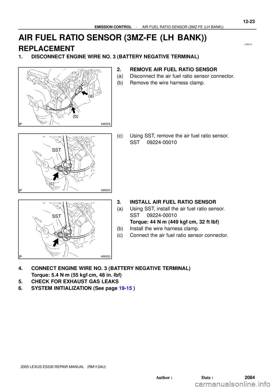
AIR FUEL RATIO SENSOR (3MZ-FE (LH BANK))
REPLACEMENT
1. DISCONNECT ENGINE WIRE NO. 3 (BATTERY NEGATIVE TERMINAL)
2. REMOVE AIR FUEL RATIO SENSOR
(a) Disconnect the air fuel ratio sensor connector.
(b) Remove the wire harness clamp.
(c) Using SST, remove the air fuel ratio sensor.
SST 09224-00010
3. INSTALL AIR FUEL RATIO SENSOR
(a) Using SST, install the air fuel ratio sensor.
SST 09224-00010
Torque: 44 NVm (449 kgfVcm, 32 ftVlbf)
(b) Install the wire harness clamp.
(c) Connect the air fuel ratio sensor connector.
4. CONNECT ENGINE WIRE NO. 3 (BATTERY NEGATIVE TERMINAL)
Torque: 5.4 NVm (55 kgfVcm, 48 in.Vlbf)
5. CHECK FOR EXHAUST GAS LEAKS
6. SYSTEM INITIALIZATION (See page 19-15)