Page 593 of 969
110XV-01
A79751
(b)(a)
(a)
A86300(c)
(e)
(e)(f)
(d)
(g)
(g)
A86297
(b)
(a)
(c)
(d)
A79706
(e)
- FUELFUEL INJECTOR ASSY (3MZ-FE)
11-13
2041 Author�: Date�:
2005 LEXUS ES330 REPAIR MANUAL (RM1124U)
REPLACEMENT
1. DISCHARGE FUEL SYSTEM PRESSURE (See page 11-1)
2. DISCONNECT ENGINE WIRE NO. 3 (BATTERY NEGATIVE TERMINAL)
3. DRAIN ENGINE COOLANT (See page 16-9)
4. REMOVE FRONT SUSPENSION UPPER BRACE CENTER (W/O TEMS) (See page 10-1 1)
5. REMOVE V-BANK COVER SUB-ASSY (See page 10-1 1)
6. REMOVE AIR CLEANER CAP SUB-ASSY (See page 10-1 1)
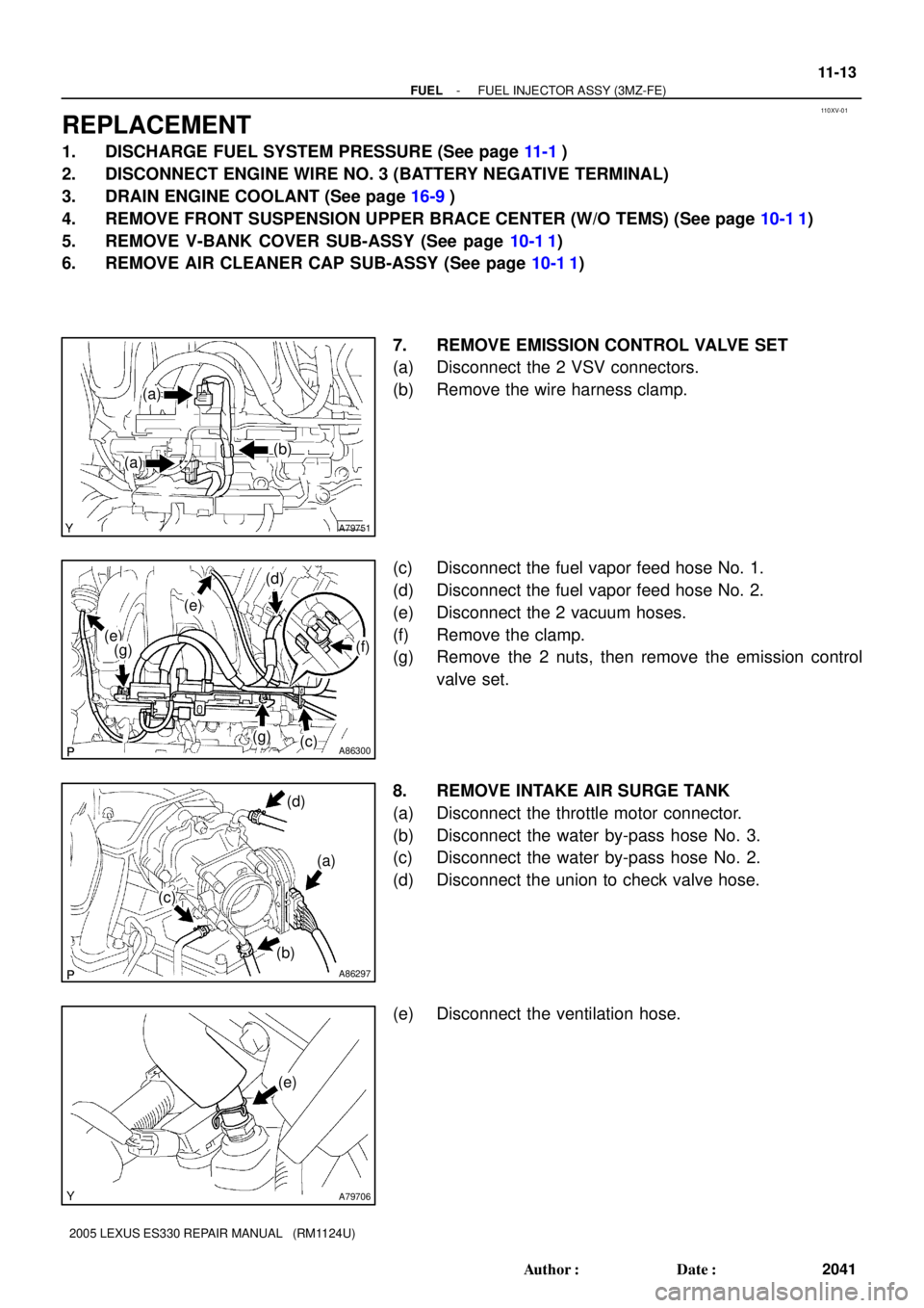
7. REMOVE EMISSION CONTROL VALVE SET
(a) Disconnect the 2 VSV connectors.
(b) Remove the wire harness clamp.
(c) Disconnect the fuel vapor feed hose No. 1.
(d) Disconnect the fuel vapor feed hose No. 2.
(e) Disconnect the 2 vacuum hoses.
(f) Remove the clamp.
(g) Remove the 2 nuts, then remove the emission control
valve set.
8. REMOVE INTAKE AIR SURGE TANK
(a) Disconnect the throttle motor connector.
(b) Disconnect the water by-pass hose No. 3.
(c) Disconnect the water by-pass hose No. 2.
(d) Disconnect the union to check valve hose.
(e) Disconnect the ventilation hose.
Page 596 of 969
A86305Turn 11-16
- FUELFUEL INJECTOR ASSY (3MZ-FE)
2044 Author�: Date�:
2005 LEXUS ES330 REPAIR MANUAL (RM1124U)
(e) Install 6 new insulators and the 4 delivery pipe No. 1
spacers to the intake manifold.
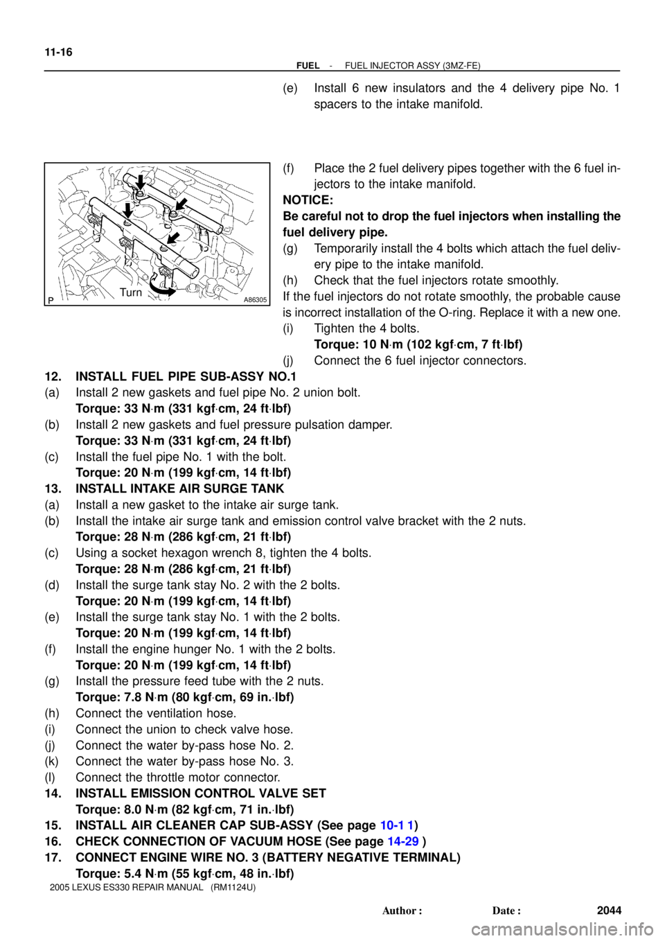
(f) Place the 2 fuel delivery pipes together with the 6 fuel in-
jectors to the intake manifold.
NOTICE:
Be careful not to drop the fuel injectors when installing the
fuel delivery pipe.
(g) Temporarily install the 4 bolts which attach the fuel deliv-
ery pipe to the intake manifold.
(h) Check that the fuel injectors rotate smoothly.
If the fuel injectors do not rotate smoothly, the probable cause
is incorrect installation of the O-ring. Replace it with a new one.
(i) Tighten the 4 bolts.
Torque: 10 NVm (102 kgfVcm, 7 ftVlbf)
(j) Connect the 6 fuel injector connectors.
12. INSTALL FUEL PIPE SUB-ASSY NO.1
(a) Install 2 new gaskets and fuel pipe No. 2 union bolt.
Torque: 33 NVm (331 kgfVcm, 24 ftVlbf)
(b) Install 2 new gaskets and fuel pressure pulsation damper.
Torque: 33 NVm (331 kgfVcm, 24 ftVlbf)
(c) Install the fuel pipe No. 1 with the bolt.
Torque: 20 NVm (199 kgfVcm, 14 ftVlbf)
13. INSTALL INTAKE AIR SURGE TANK
(a) Install a new gasket to the intake air surge tank.
(b) Install the intake air surge tank and emission control valve bracket with the 2 nuts.
Torque: 28 NVm (286 kgfVcm, 21 ftVlbf)
(c) Using a socket hexagon wrench 8, tighten the 4 bolts.
Torque: 28 NVm (286 kgfVcm, 21 ftVlbf)
(d) Install the surge tank stay No. 2 with the 2 bolts.
Torque: 20 NVm (199 kgfVcm, 14 ftVlbf)
(e) Install the surge tank stay No. 1 with the 2 bolts.
Torque: 20 NVm (199 kgfVcm, 14 ftVlbf)
(f) Install the engine hunger No. 1 with the 2 bolts.
Torque: 20 NVm (199 kgfVcm, 14 ftVlbf)
(g) Install the pressure feed tube with the 2 nuts.
Torque: 7.8 NVm (80 kgfVcm, 69 in.Vlbf)
(h) Connect the ventilation hose.
(i) Connect the union to check valve hose.
(j) Connect the water by-pass hose No. 2.
(k) Connect the water by-pass hose No. 3.
(l) Connect the throttle motor connector.
14. INSTALL EMISSION CONTROL VALVE SET
Torque: 8.0 NVm (82 kgfVcm, 71 in.Vlbf)
15. INSTALL AIR CLEANER CAP SUB-ASSY (See page 10-1 1)
16. CHECK CONNECTION OF VACUUM HOSE (See page 14-29)
17. CONNECT ENGINE WIRE NO. 3 (BATTERY NEGATIVE TERMINAL)
Torque: 5.4 NVm (55 kgfVcm, 48 in.Vlbf)
Page 597 of 969
- FUELFUEL INJECTOR ASSY (3MZ-FE)
11-17
2045 Author�: Date�:
2005 LEXUS ES330 REPAIR MANUAL (RM1124U)
18. ADD ENGINE COOLANT (See page 16-9)
19. CHECK FOR ENGINE COOLANT LEAKS (See page 16-1)
20. CHECK FOR FUEL LEAKS (See page 11-5)
21. INSTALL V-BANK COVER SUB-ASSY (See page 10-1 1)
22. INSTALL FRONT SUSPENSION UPPER BRACE CENTER (W/O TEMS) (See page 10-1 1)
23. SYSTEM INITIALIZATION (See page 19-15)
Page 600 of 969
110XX-02
A79487
(b)
(c)
A91017
Nylon Tube Fuel Tube Joint
O-ring
Tube Joint Clip Fuel Suction Plate
A79488
Tube Joint Clip
A79489
(b)
(b)
(b)(b)(b)
(b)
(b)
(b) 11-20
- FUELFUEL SUCTION W/ PUMP & GAUGE TUBE
ASSY (3MZ-FE)
2048 Author�: Date�:
2005 LEXUS ES330 REPAIR MANUAL (RM1124U)
Removal & Installation and Disassembly & Reassembly
1. DISCHARGE FUEL SYSTEM PRESSURE (See page 11-1)
2. DISCONNECT ENGINE WIRE NO. 3 (BATTERY NEGATIVE TERMINAL)
3. REMOVE REAR SEAT CUSHION ASSY (See page 72-39)
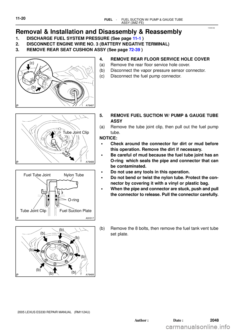
4. REMOVE REAR FLOOR SERVICE HOLE COVER
(a) Remove the rear floor service hole cover.
(b) Disconnect the vapor pressure sensor connector.
(c) Disconnect the fuel pump connector.
5. REMOVE FUEL SUCTION W/ PUMP & GAUGE TUBE
ASSY
(a) Remove the tube joint clip, then pull out the fuel pump
tube.
NOTICE:
�Check around the connector for dirt or mud before
this operation. Remove the dirt if necessary.
�Be careful of mud because the fuel tube joint has an
O-ring which seals the pipe and connector that can
be contaminated.
�Do not use any tools in this operation.
�Do not bend or twist the nylon tube. Protect the con-
nector by covering it with a vinyl or plastic bag.
�When the pipe and connector are stuck, push and pull
the connector to release. Pull the connector carefully.
(b) Remove the 8 bolts, then remove the fuel tank vent tube
set plate.
Page 604 of 969
A79489Mark
A81595
Tube Joint ClipCollar
A79487
New Butyl Tape
11-24- FUELFUEL SUCTION W/ PUMP & GAUGE TUBE
ASSY (3MZ-FE)
2052 Author�: Date�:
2005 LEXUS ES330 REPAIR MANUAL (RM1124U)
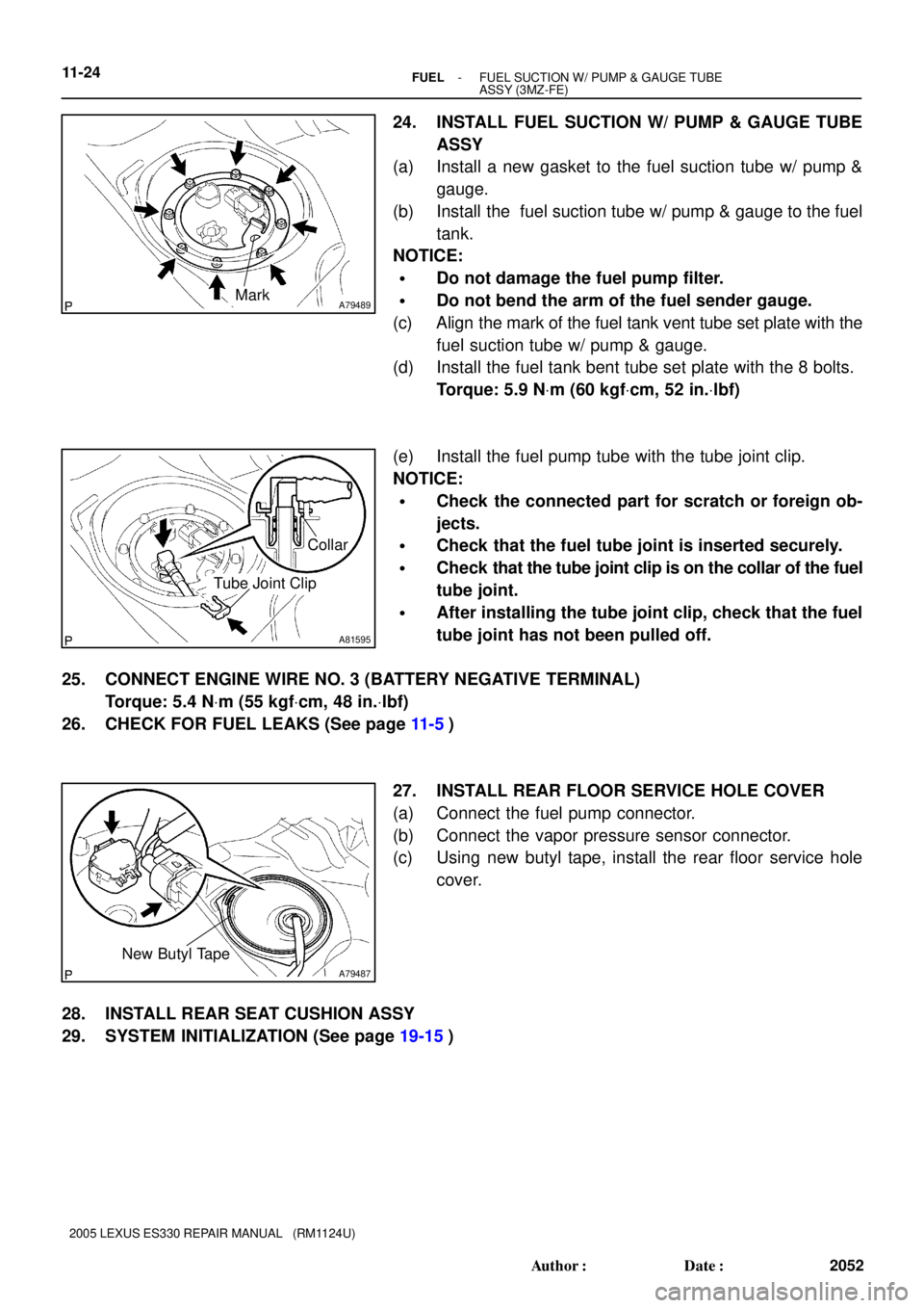
24. INSTALL FUEL SUCTION W/ PUMP & GAUGE TUBE
ASSY
(a) Install a new gasket to the fuel suction tube w/ pump &
gauge.
(b) Install the fuel suction tube w/ pump & gauge to the fuel
tank.
NOTICE:
�Do not damage the fuel pump filter.
�Do not bend the arm of the fuel sender gauge.
(c) Align the mark of the fuel tank vent tube set plate with the
fuel suction tube w/ pump & gauge.
(d) Install the fuel tank bent tube set plate with the 8 bolts.
Torque: 5.9 NVm (60 kgfVcm, 52 in.Vlbf)
(e) Install the fuel pump tube with the tube joint clip.
NOTICE:
�Check the connected part for scratch or foreign ob-
jects.
�Check that the fuel tube joint is inserted securely.
�Check that the tube joint clip is on the collar of the fuel
tube joint.
�After installing the tube joint clip, check that the fuel
tube joint has not been pulled off.
25. CONNECT ENGINE WIRE NO. 3 (BATTERY NEGATIVE TERMINAL)
Torque: 5.4 NVm (55 kgfVcm, 48 in.Vlbf)
26. CHECK FOR FUEL LEAKS (See page 11-5)
27. INSTALL REAR FLOOR SERVICE HOLE COVER
(a) Connect the fuel pump connector.
(b) Connect the vapor pressure sensor connector.
(c) Using new butyl tape, install the rear floor service hole
cover.
28. INSTALL REAR SEAT CUSHION ASSY
29. SYSTEM INITIALIZATION (See page 19-15)
Page 613 of 969
A81598
Retainer
Push
- FUELFUEL TANK ASSY (3MZ-FE)
11-33
2061 Author�: Date�:
2005 LEXUS ES330 REPAIR MANUAL (RM1124U)
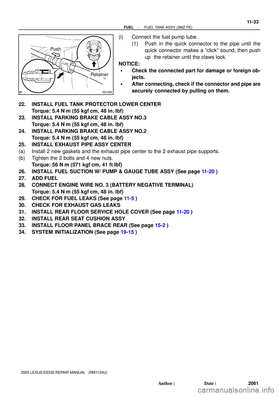
(i) Connect the fuel pump tube.
(1) Push in the quick connector to the pipe until the
quick connector makes a ºclickº sound, then push
up the retainer until the claws lock.
NOTICE:
�Check the connected part for damage or foreign ob-
jects.
�After connecting, check if the connector and pipe are
securely connected by pulling on them.
22. INSTALL FUEL TANK PROTECTOR LOWER CENTER
Torque: 5.4 NVm (55 kgfVcm, 48 in.Vlbf)
23. INSTALL PARKING BRAKE CABLE ASSY NO.3
Torque: 5.4 NVm (55 kgfVcm, 48 in.Vlbf)
24. INSTALL PARKING BRAKE CABLE ASSY NO.2
Torque: 5.4 NVm (55 kgfVcm, 48 in.Vlbf)
25. INSTALL EXHAUST PIPE ASSY CENTER
(a) Install 2 new gaskets and the exhaust pipe center to the 2 exhaust pipe supports.
(b) Tighten the 2 bolts and 4 new nuts.
Torque: 56 NVm (571 kgfVcm, 41 ftVlbf)
26. INSTALL FUEL SUCTION W/ PUMP & GAUGE TUBE ASSY (See page 11-20)
27. ADD FUEL
28. CONNECT ENGINE WIRE NO. 3 (BATTERY NEGATIVE TERMINAL)
Torque: 5.4 NVm (55 kgfVcm, 48 in.Vlbf)
29. CHECK FOR FUEL LEAKS (See page 11-5)
30. CHECK FOR EXHAUST GAS LEAKS
31. INSTALL REAR FLOOR SERVICE HOLE COVER (See page 11-20)
32. INSTALL REAR SEAT CUSHION ASSY
33. INSTALL FLOOR PANEL BRACE REAR (See page 15-2)
34. SYSTEM INITIALIZATION (See page 19-15)
Page 616 of 969
120C1-02
G37992
Voltmeter E9 E8
A86347DLC3
Hand-held Tester
A86385
Lean
14.7 3.3 V
RichAir
Fuel
Ratio
Time Keep the engine speed
- EMISSION CONTROLEMISSION CONTROL SYSTEM (3MZ-FE)
12-3
2064 Author�: Date�:
2005 LEXUS ES330 REPAIR MANUAL (RM1124U)
ON-VEHICLE INSPECTION
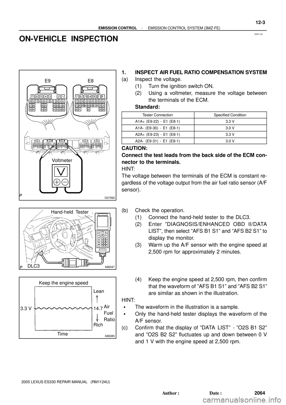
1. INSPECT AIR FUEL RATIO COMPENSATION SYSTEM
(a) Inspect the voltage.
(1) Turn the ignition switch ON.
(2) Using a voltmeter, measure the voltage between
the terminals of the ECM.
Standard:
Tester ConnectionSpecified Condition
A1A+ (E9-22) - E1 (E8-1)3.3 V
A1A- (E9-30) - E1 (E8-1)3.0 V
A2A+ (E9-23) - E1 (E8-1)3.3 V
A2A- (E9-31) - E1 (E8-1)3.0 V
CAUTION:
Connect the test leads from the back side of the ECM con-
nector to the terminals.
HINT:
The voltage between the terminals of the ECM is constant re-
gardless of the voltage output from the air fuel ratio sensor (A/F
sensor).
(b) Check the operation.
(1) Connect the hand-held tester to the DLC3.
(2) Enter ºDIAGNOSIS/ENHANCED OBD II/DATA
LISTº, then select ºAFS B1 S1º and ºAFS B2 S1º to
display the monitor.
(3) Warm up the A/F sensor with the engine speed at
2,500 rpm for approximately 2 minutes.
(4) Keep the engine speed at 2,500 rpm, then confirm
that the waveform of ºAFS B1 S1º and ºAFS B2 S1º
are similar as shown in the illustration.
HINT:
�The waveform in the illustration is a sample.
�Only the hand-held tester displays the waveform of the
A/F sensor.
(c) Confirm that the display of ºDATA LISTº - ºO2S B1 S2º
and ºO2S B2 S2º fluctuates up and down between 0 V
and 1 V with the engine speed at 2,500 rpm.
Page 617 of 969
A86346
A59499
Vacuum Gauge
A86347DLC3
Hand-held Tester
12-4
- EMISSION CONTROLEMISSION CONTROL SYSTEM (3MZ-FE)
2065 Author�: Date�:
2005 LEXUS ES330 REPAIR MANUAL (RM1124U)
2. INSPECT FUEL CUT OFF RPM
(a) Check the operation.
(1) Increase the engine speed to at least 3,500 rpm.
(2) Use a sound scope to check the fuel injector operating noise.
(3) Check that when the throttle lever is released, the fuel injector operation noise stops momentarily
at 2,500 rpm and then resumes at 1,200 rpm.
2,500 rpm: Fuel cut off rpm
1,200 rpm: Fuel return rpm
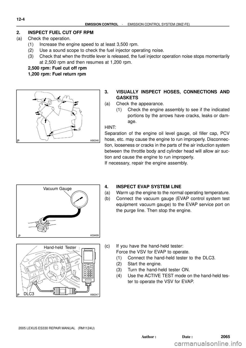
3. VISUALLY INSPECT HOSES, CONNECTIONS AND
GASKETS
(a) Check the appearance.
(1) Check the engine assembly to see if the indicated
portions by the arrows have cracks, leaks or dam-
age.
HINT:
Separation of the engine oil level gauge, oil filler cap, PCV
hose, etc. may cause the engine to run improperly. Disconnec-
tion, looseness or cracks in the parts of the air induction system
between the throttle body and cylinder head will allow air suc-
tion and cause the engine to run improperly.
If necessary, repair the engine assembly.
4. INSPECT EVAP SYSTEM LINE
(a) Warm up the engine to the normal operating temperature.
(b) Connect the vacuum gauge (EVAP control system test
equipment vacuum gauge) to the EVAP service port on
the purge line. Then stop the engine.
(c) If you have the hand-held tester:
Force the VSV for EVAP to operate.
(1) Connect the hand-held tester to the DLC3.
(2) Start the engine.
(3) Turn the hand-held tester ON.
(4) Use the ACTIVE TEST mode on the hand-held tes-
ter to operate the VSV for EVAP.