Page 57 of 136

14±17
1CD±FTV ENGINE REPAIR MANUAL (RM927E)
42. INSTA")
A57098
A09600
Seal Width
2 ± 4 mm
Seal Packing
SST
A57101
Inward
Angle Sensor
A57102
Turn
± ENGINE MECHANICALPARTIAL ENGINE ASSY (1CD±FTV)
14±17
1CD±FTV ENGINE REPAIR MANUAL (RM927E)
42. INSTALL WATER PUMP ASSY
(a) Install a new gasket and the water pump with the 7bolts.
Torque: 31 N�m (320 kgf�cm, 23 ft�lbf)
43. INSTALL CAMSHAFT OIL SEAL RETAINER
(a) Apply seal packing to the oil seal retainer as shown in the
illustration.
Seal packing: Part No. 08826±00080 or equivalent
NOTICE:
�Install a nozzle that has been cut to a 2 ± 4 mm (0.08
± 0.16 in.) opening.
�Parts must be assembled within 15 minutes of ap-
plication. Otherwise the material must be removed
and reapplied.
�Immediately remove nozzle from the tube and rein-
stall the cap.
(b) Install the oil seal retainer with 4 bolts. Uniformly tighten
the 4 bolts in several passes.
Torque: 8.8 N�m (90 kgf�cm, 78 in.�lbf)
44. INSTALL CRANKSHAFT TIMING PULLEY
(a) Align the pulley set key with the key groove of the timing
pulley.
(b) Using SST and a hammer, tap in the timing pulley, facing
the angle sensor inward.
SST 09223±46011
45. INSTALL TIMING BELT IDLER SUB±ASSY NO.2
(a) Install the idler pulley with the bolt.
Torque: 47 N�m (475 kgf�cm, 34 ft�lbf)
(b) Check that the idler pulley moves smoothly.
Page 58 of 136

A62592
SST
B08252
B09792
Spring
Convex
14±18
± ENGINE MECHANICALPARTIAL ENGINE ASSY (1CD±FTV)
1CD±FTV ENGINE REPAIR MANUAL (RM927E)
46. INSTALL TIMING B")
A57103
Plate Washer
Hexagon
Wrench
(8mm)
A62592
SST
B08252
B09792
Spring
Convex
14±18
± ENGINE MECHANICALPARTIAL ENGINE ASSY (1CD±FTV)
1CD±FTV ENGINE REPAIR MANUAL (RM927E)
46. INSTALL TIMING BELT IDLER SUB±ASSY NO.1
(a) Using an hexagon wrench (8mm), install the plate washer
and idler pulley with the idler pulley shaft.
Torque: 35 N�m (350 kgf�cm, 25 ft�lbf)
(b) Check that the pulley bracket moves smoothly.
47. INSTALL CAMSHAFT TIMING PULLEY
(a) Install the pulley set key to the key groove of the cam-
shaft.
(b) Align the pulley set key with the key groove of the timing
pulley, and slide on the timing pulley.
(c) Using SST, install the pulley bolt.
SST 09960±10010 (09962±01000, 09963±01000)
Torque: 88 N�m (899 kgf�cm, 65 ft�lbf)
48. INSTALL INJECTOR ASSY
(a) Install 4 new nozzle seats to the cylinder head.
(b) Set the spring to each injector.
NOTICE:
Be sure to make the opening direction of the spring and the
direction of the injector positioning convex meet.
(c) Install a new back±up ring and O±ring to each injector.
(d) Apply a light coat of oil onto O±ring for each injector.
Page 59 of 136

14±19
1CD±FTV ENGINE REPAIR MANUAL (RM927E)
(e) Meet the injector positioning convex to the positionin")
B09793
Convex
Concave
B08249
Upward
B08253
± ENGINE MECHANICALPARTIAL ENGINE ASSY (1CD±FTV)
14±19
1CD±FTV ENGINE REPAIR MANUAL (RM927E)
(e) Meet the injector positioning convex to the positioning
concave at the cylinder head side and install the injector
to the cylinder head.
NOTICE:
�At this time, insert the injector until it touches the
nozzle sheet surface.
�When installing the injector to the cylinder head and
in case that the injector comes to float up with the
reaction of O±ring, pull out the injector once, install
it again.
�During the time after equipping the head cover and
before installing the injection pipe, install the irregu-
lar object prevention cover.
�Do not exchange the injector cylinder.
(f) Place the 4 nozzle holder clamps to each injector.
49. INSTALL NOZZLE HOLDER CLAMP
(a) Set the washer on the nozzle holder clamp as shown in
the illustration.
(b) Tighten the bolts.
HINT:
Apply a light coat of engine oil on the threads and under the
heads of the nozzle holder clamp bolts.
Torque: 27 N�m (275 kgf�cm, 20 ft�lbf)
NOTICE:
At this time, the clamp has its cam cap bolt as a fulcrum and
clip the injector at the fork portion.
Page 60 of 136

1CD±FTV ENGINE REPAIR MANUAL (RM927E)
50. INSTALL NOZZLE LEAKAGE PIPE A")
90�
180�
B08307
B08311
B08312
Plug
GasketOverflow Screw
Ball Spring 14±20
± ENGINE MECHANICALPARTIAL ENGINE ASSY (1CD±FTV)
1CD±FTV ENGINE REPAIR MANUAL (RM927E)
50. INSTALL NOZZLE LEAKAGE PIPE ASSY
(a) Place the leakage pipe and 5 new gaskets.
NOTICE:
Do the installation of the gasket craw within the angle
range shown in the illustration.
(b) Apply a light coat of oil onto 4 hollow screws and union
bolt.
(c) Tighten the 4 hollow screws and union bolt by hand.
(d) Tighten the 4 hollow screws and union bolt.
Torque:
Hollow screw 18 N�m (184 kgf�cm, 13 ft�lbf)
Union bolt 22 N�m (224 kgf�cm, 16 ft�lbf)
(e) Check that there is no leak from nozzle leakage pipe con-
nection.
(1) Disconnect the fuel hose, and remove the check
valve, No. 2 nozzle leakage pipe and gasket.
(2) Purchase a new check valve.
HINT:
Part No. 23122±27010
(3) Remove the plug, gasket, spring and ball.
(4) Install the plug with the gasket to the overflow
screw.
Torque: 9.8 N�m (100 kgf�cm, 7 ft.�lbf)
(5) Install the No. 2 nozzle leakage pipe and gasket
with the check valve to the cylinder head.
Torque: 21 N�m (214 kgf�cm, 15 ft�lbf)
(6) Apply a light coat of soapy water (any fluid to detect
fuel leakage) on the nozzle leakage pipe connec-
tion.
Page 61 of 136

A56050
New Gasket
Union Bolt
Hollow
Screw
SST
No. 2 Nozzle
Leakage Pipe
Check
Valve
New Gasket
B08328
Check
ValveNo. 2 Nozzle
Leakage Pipe
New Gasket
A09663
: Seal Packing
± ENGINE MECHANICALPARTIAL ENGINE ASSY (1CD±FTV)
14±21
1CD±FTV ENGINE REPAIR MANUAL (RM927E)
(7) Using SST (turbocharger pressure gauge), apply
the SST to the fuel return side of the No. 2 nozzle
leakage pipe, and maintain 100 kPa (1 kgf/cm
2,
14.5 psi) of pressure for 600 seconds to check that
there are no bubbles from the soap±applied places.
SST 09992±00242
(8) After checking fuel leaks, wipe off soapy water from
nozzle leakage pipe connection.
(9) Remove SST, check valve, No. 2 nozzle leakage
pipe and gasket.
(10) Reinstall the No. 2 nozzle leakage pipe and a new
gasket with the check valve.
Torque: 21 N�m (214 kgf�cm, 15 ft�lbf)
HINT:
Never reinstall the disassembled check valve on the engine.
(11) Reconnect the fuel hose to the No. 2 nozzle leak-
age pipe.
51. INSTALL CYLINDER HEAD COVER SUB±ASSY
(a) Remove any old packing (FIPG) material.
(b) Apply seal packing to the cylinder head.
Seal packing: Part No. 08826±00080 or equivalent
(c) Install the gasket to the head cover.
(d) Install the cylinder head cover with 10 bolts.
Torque: 13 N�m (135 kgf�cm, 10 ft�lbf)
(e) Install 4 new nozzle holder seals.
Page 62 of 136
140L5±01
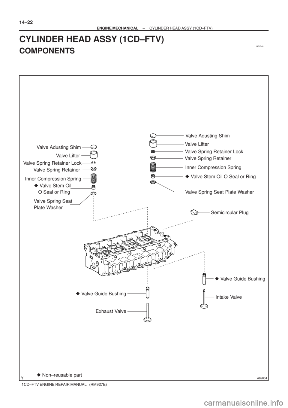
A62604� Non±reusable part � Valve Stem Oil
O Seal or RingValve Adusting Shim
Valve Lifter
Valve Spring Retainer
Valve Spring Retainer Lock
Inner Compression Spring
Valve Spring Seat
Plate Washer
� Valve Guide Bushing
Exhaust Valve
Semicircular Plug
� Valve Stem Oil O Seal or Ring Valve Adusting Shim
Valve Lifter
Valve Spring RetainerValve Spring Retainer Lock
Inner Compression Spring
Valve Spring Seat Plate Washer
� Valve Guide Bushing
Intake Valve
14±22
± ENGINE MECHANICALCYLINDER HEAD ASSY (1CD±FTV)
1CD±FTV ENGINE REPAIR MANUAL (RM927E)
CYLINDER HEAD ASSY (1CD±FTV)
COMPONENTS
Page 63 of 136
140DR±03
A56671
SST
A62594
SST
A09561
A09676
± ENGINE MECHANICALCYLINDER HEAD ASSY (1CD±FTV)
14±23
1CD±FTV ENGINE REPAIR MANUAL (RM927E)
OVERHAUL
1. REMOVE VALVE LIFTER
HINT:
Arrange the valve lifters in the correct order.
2. REMOVE INTAKE VALVE
(a) Using SST, compress the valve spring and remove the 2
keepers.
SST 09202±70020 (09202±00010)
(b) Remove the spring retainer, valve spring and valve.
3. REMOVE EXHAUST VALVE
(a) Using SST, compress the valve spring and remove the 2
keepers.
SST 09202±70020 (09202±00010)
(b) Remove the spring retainer, valve spring and valve.
4. REMOVE VALVE STEM OIL O SEAL OR RING
(a) Using needle±nose pliers, remove the oil seal.
5. REMOVE VALVE SPRING SEAT PLATE WASHER
(a) Using compressed air and a magnetic finger, remove the
spring seat by blowing air.
HINT:
Arrange the valves, valve springs, spring seats and spring re-
tainers in the correct order.
Page 64 of 136
A62595
A56049
Cylinder Block Side
Intake Manifold Side
Exhaust Manifold Side
A09534
14±24
± ENGINE MECHANICALCYLINDER HEAD ASSY (1CD±FTV)
1CD±FTV ENGINE REPAIR MANUAL (RM927E)
6. REMOVE SEMICIRCULAR PLUG
7. REMOVE W/HEAD TAPER SCREW PLUG NO.1
(a) Using a hexagon wrench (6mm), remove the 3 plugs.
SST 99999±70037
8. INSPECT CYLINDER HEAD FOR FLATNESS
(a) Using a precision straight edge and feeler gauge, mea-
sure the surfaces contacting the cylinder block and the
manifolds for warpage.
Maximum warpage:
Cylinder block side0.08mm (0.0031in.)
Intake manifold side0.20mm (0.0079in.)
Exhaust manifold side0.20mm (0.0079in.)
9. INSPECT CYLINDER HEAD FOR CRACKS
(a) Using dye penetrant, check the intake ports, exhaust
ports and cylinder block contact surface for cracks.

14±23
1CD±FTV ENGINE REPAIR MANUAL (RM927E)
OVERHAUL
1. REMOVE VALVE LIFTER
HINT:
Arrange the valve")

1CD±FTV ENGINE REPAIR MANUAL (RM927E)
6. REMOVE SEMICIRC")