Page 58 of 136
A57103
Plate Washer
Hexagon
Wrench
(8mm)
A62592
SST
B08252
B09792
Spring
Convex
14±18
± ENGINE MECHANICALPARTIAL ENGINE ASSY (1CD±FTV)
1CD±FTV ENGINE REPAIR MANUAL (RM927E)
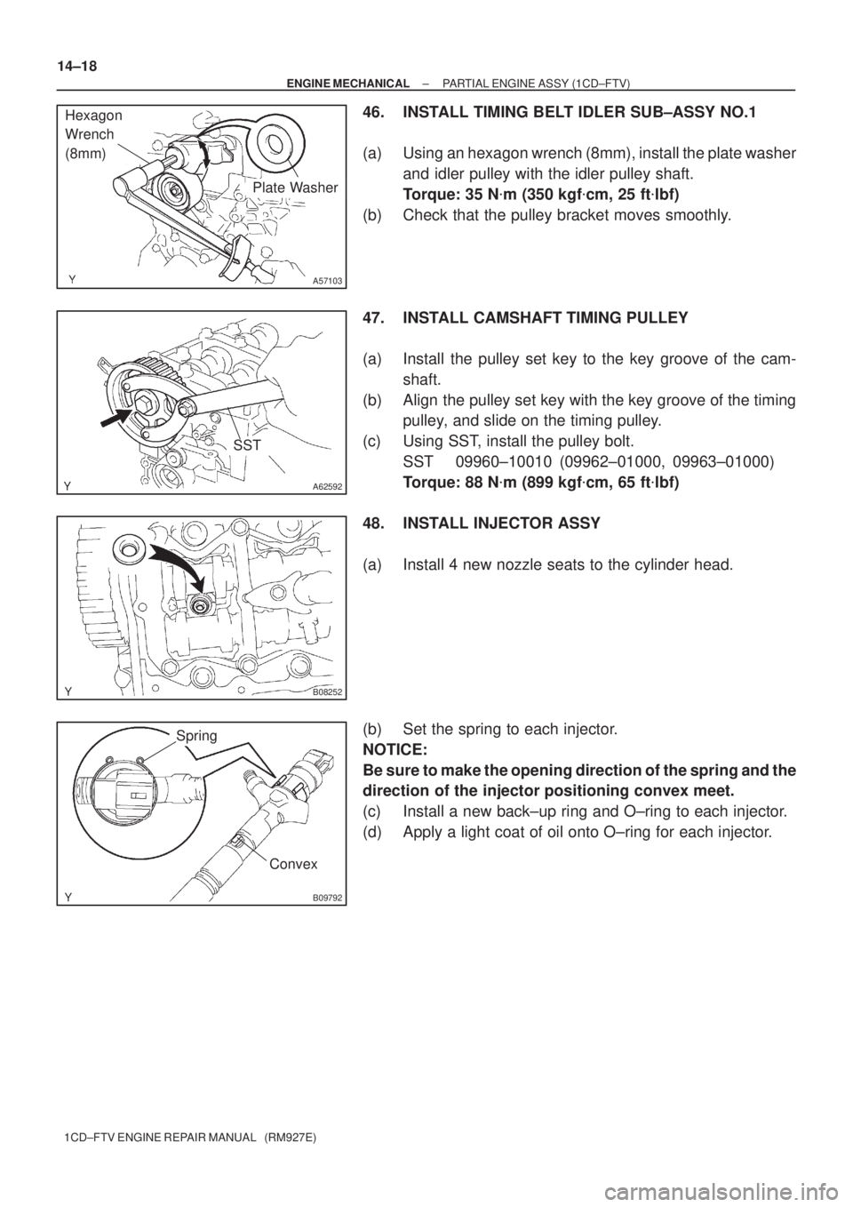
46. INSTALL TIMING BELT IDLER SUB±ASSY NO.1
(a) Using an hexagon wrench (8mm), install the plate washer
and idler pulley with the idler pulley shaft.
Torque: 35 N�m (350 kgf�cm, 25 ft�lbf)
(b) Check that the pulley bracket moves smoothly.
47. INSTALL CAMSHAFT TIMING PULLEY
(a) Install the pulley set key to the key groove of the cam-
shaft.
(b) Align the pulley set key with the key groove of the timing
pulley, and slide on the timing pulley.
(c) Using SST, install the pulley bolt.
SST 09960±10010 (09962±01000, 09963±01000)
Torque: 88 N�m (899 kgf�cm, 65 ft�lbf)
48. INSTALL INJECTOR ASSY
(a) Install 4 new nozzle seats to the cylinder head.
(b) Set the spring to each injector.
NOTICE:
Be sure to make the opening direction of the spring and the
direction of the injector positioning convex meet.
(c) Install a new back±up ring and O±ring to each injector.
(d) Apply a light coat of oil onto O±ring for each injector.
Page 63 of 136
140DR±03
A56671
SST
A62594
SST
A09561
A09676
± ENGINE MECHANICALCYLINDER HEAD ASSY (1CD±FTV)
14±23
1CD±FTV ENGINE REPAIR MANUAL (RM927E)
OVERHAUL
1. REMOVE VALVE LIFTER
HINT:
Arrange the valve lifters in the correct order.
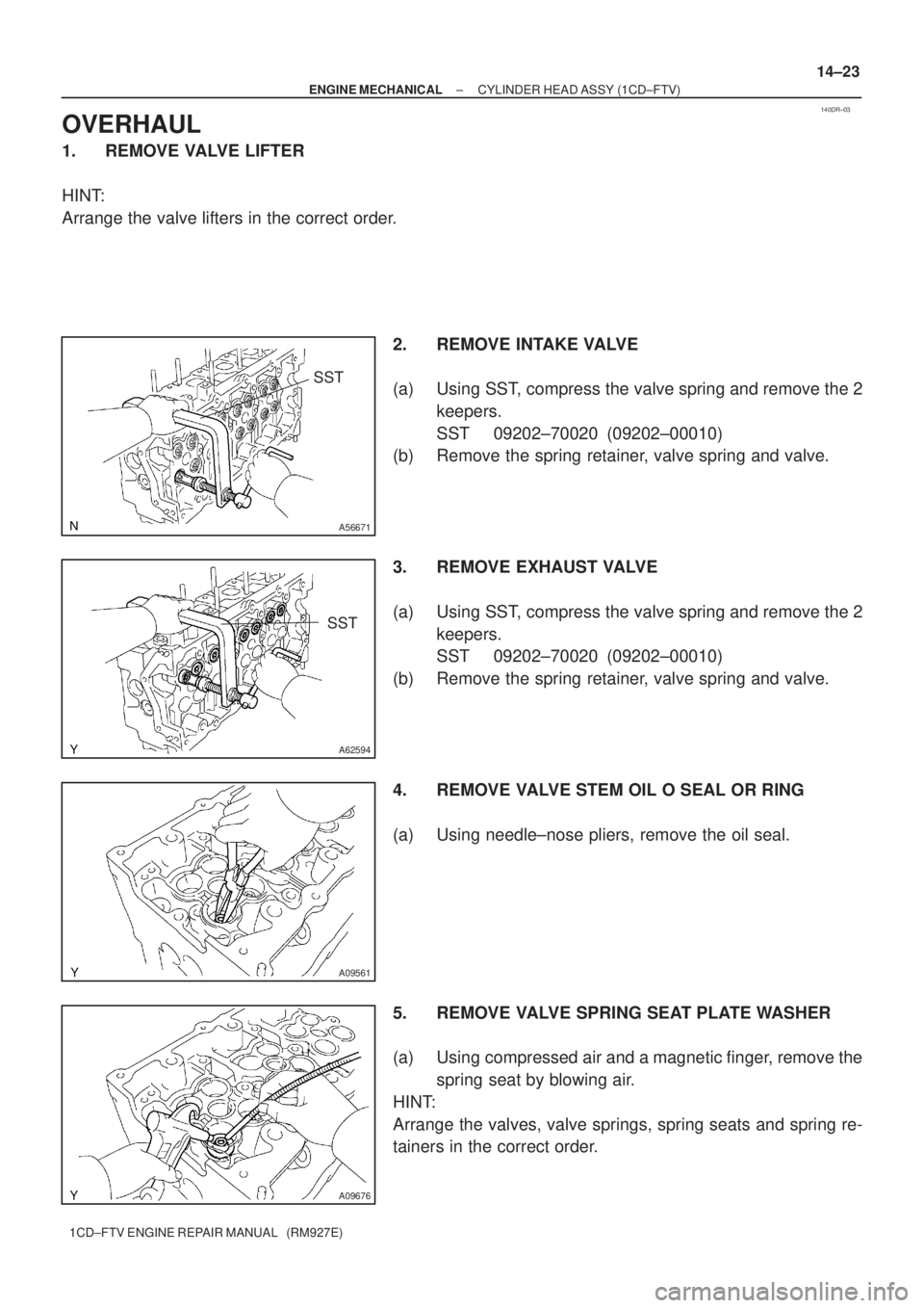
2. REMOVE INTAKE VALVE
(a) Using SST, compress the valve spring and remove the 2
keepers.
SST 09202±70020 (09202±00010)
(b) Remove the spring retainer, valve spring and valve.
3. REMOVE EXHAUST VALVE
(a) Using SST, compress the valve spring and remove the 2
keepers.
SST 09202±70020 (09202±00010)
(b) Remove the spring retainer, valve spring and valve.
4. REMOVE VALVE STEM OIL O SEAL OR RING
(a) Using needle±nose pliers, remove the oil seal.
5. REMOVE VALVE SPRING SEAT PLATE WASHER
(a) Using compressed air and a magnetic finger, remove the
spring seat by blowing air.
HINT:
Arrange the valves, valve springs, spring seats and spring re-
tainers in the correct order.
Page 69 of 136
A56676
A56677
SST
A56678
Sharp 6 mm
Reamer
± ENGINE MECHANICALCYLINDER HEAD ASSY (1CD±FTV)
14±29
1CD±FTV ENGINE REPAIR MANUAL (RM927E)
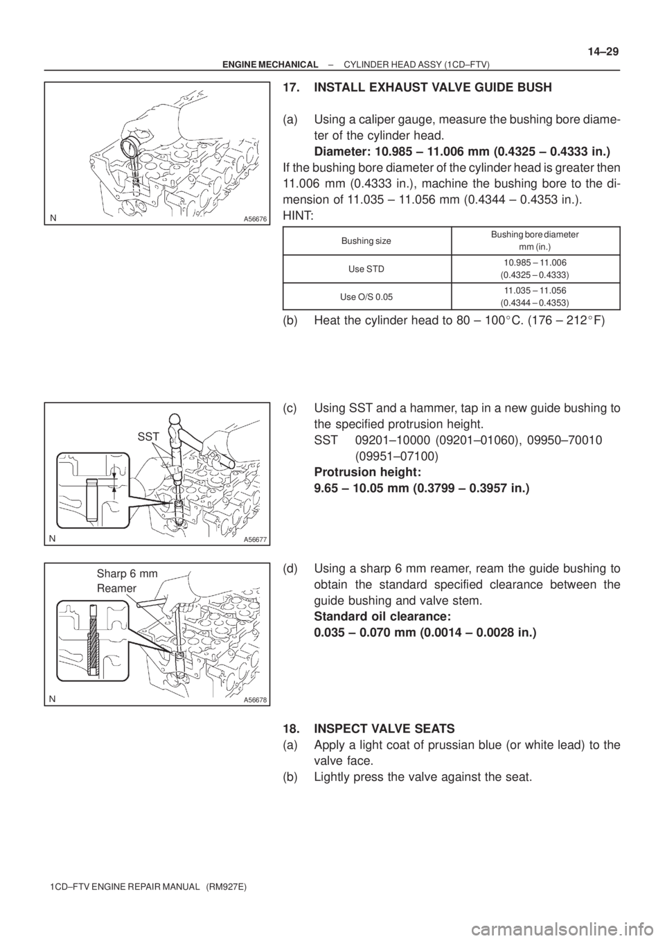
17. INSTALL EXHAUST VALVE GUIDE BUSH
(a) Using a caliper gauge, measure the bushing bore diame-
ter of the cylinder head.
Diameter: 10.985 ± 11.006 mm (0.4325 ± 0.4333 in.)
If the bushing bore diameter of the cylinder head is greater then
11.006 mm (0.4333 in.), machine the bushing bore to the di-
mension of 11.035 ± 11.056 mm (0.4344 ± 0.4353 in.).
HINT:
Bushing sizeBushing bore diameter
mm (in.)
Use STD10.985 ± 11.006
(0.4325 ± 0.4333)
Use O/S 0.0511.035 ± 11.056
(0.4344 ± 0.4353)
(b) Heat the cylinder head to 80 ± 100�C. (176 ± 212�F)
(c) Using SST and a hammer, tap in a new guide bushing to
the specified protrusion height.
SST 09201±10000 (09201±01060), 09950±70010
(09951±07100)
Protrusion height:
9.65 ± 10.05 mm (0.3799 ± 0.3957 in.)
(d) Using a sharp 6 mm reamer, ream the guide bushing to
obtain the standard specified clearance between the
guide bushing and valve stem.
Standard oil clearance:
0.035 ± 0.070 mm (0.0014 ± 0.0028 in.)
18. INSPECT VALVE SEATS
(a) Apply a light coat of prussian blue (or white lead) to the
valve face.
(b) Lightly press the valve against the seat.
Page 70 of 136

A56053
Width
45�25�
Z03988
45�
70�
A57105Contacting Width
A09537
14±30
± ENGINE MECHANICALCYLINDER HEAD ASSY (1CD±FTV)
1CD±FTV ENGINE REPAIR MANUAL (RM927E)
(c) Check the valve face and seat according to the following
procedure.
(1) If blue appears 360� around the face, the valve is
concentric. If not, replace the valve.
(2) If blue appears 360� around the valve seat, the
guide and face are concentric. If not, resurface the
seat.
(3) Check that the seat contact is in the middle of the
valve face with the following width.
Intake1.2 ± 1.6 mm (0.047 ± 0.063 in.)
Exhaust1.6 ± 2.0 mm (0.063 ± 0.079 in.)
19. REPAIR INTAKE VALVE SEATS
NOTICE:
Take off a cutter gradually to make smooth valve seats.
(a) If the seating is too high on the valve face, use 25� and
45� cutters to correct the seat.
(b) If the seating is too low on the valve face, use 70 � and
45� cutters to correct the seat.
(c) Hand±lap the valve and valve seat with an abrasive com-
pound.
(d) Check the valve seating position.
SST 99999±60014
Page 71 of 136
45�25�
Z03988
45�
65�
A57106
A56679
EM2196
A09544
± ENGINE MECHANICALCYLINDER HEAD ASSY (1CD±FTV)
14±31
1CD±FTV ENGINE REPAIR MANUAL (RM927E)
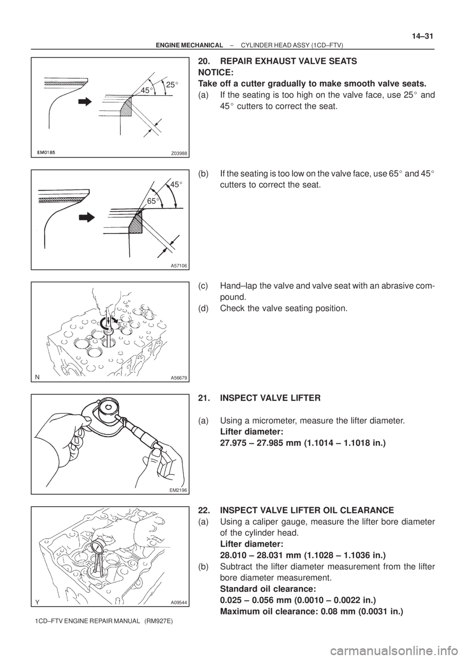
20. REPAIR EXHAUST VALVE SEATS
NOTICE:
Take off a cutter gradually to make smooth valve seats.
(a) If the seating is too high on the valve face, use 25� and
45� cutters to correct the seat.
(b) If the seating is too low on the valve face, use 65� and 45�
cutters to correct the seat.
(c) Hand±lap the valve and valve seat with an abrasive com-
pound.
(d) Check the valve seating position.
21. INSPECT VALVE LIFTER
(a) Using a micrometer, measure the lifter diameter.
Lifter diameter:
27.975 ± 27.985 mm (1.1014 ± 1.1018 in.)
22. INSPECT VALVE LIFTER OIL CLEARANCE
(a) Using a caliper gauge, measure the lifter bore diameter
of the cylinder head.
Lifter diameter:
28.010 ± 28.031 mm (1.1028 ± 1.1036 in.)
(b) Subtract the lifter diameter measurement from the lifter
bore diameter measurement.
Standard oil clearance:
0.025 ± 0.056 mm (0.0010 ± 0.0022 in.)
Maximum oil clearance: 0.08 mm (0.0031 in.)