Page 1 of 136

0106E±06
A54988
N´m (kgf´cm, ft´lbf) : Specified torque
� Non±reusable partCamshaft Timing Tube AssyCamshaft Drive Gear
Seal Washer
� Camshaft Setting Oil SealNo. 2 Camshaft,
No. 4 Camshaft Sub±assy
Wave WasherCamshaft Driven Main Gear
Snap RingCamshaft Timing Gear
Bolt Washer Screw Plug
78 (790, 58)
15 (150, 11)
7.5 (80, 66 in.´lbf)
Camshaft Sub Gear
Camshaft,
No. 3 Camshaft Sub±assy OVERHAUL
± INTRODUCTIONHOW TO USE THIS MANUAL
01±1
1CD±FTV ENGINE REPAIR MANUAL (RM927E)
HOW TO USE THIS MANUAL
GENERAL INFORMATION
1. GENERAL DESCRIPTION
(a) This manual is made in accordance with SAE J2008.
(b) Generally repair operations can be separated in the following 3 main processes:
1. Diagnosis
2. Removing and Installing, Replacing, Disassembling, Installing and Checking, Adjusting
3. Final Inspection
(c) This manual explains ºRemoving and Installing, Replacing, Disassembling, Installing and Checking,
Adjustingº, but ºFinal Inspectionº is omitted.
(d) The following essential operations are not written in this manual, however these operations must be
done in the practical situation.
(1) Operation with a jack or lift
(2) Cleaning of a removed part when necessary
(3) Visual check
2. INDEX
(a) An alphabetical INDEX is provided as a section on the end of the book to guide you to the item to be
repaired.
3. PREPARATION
(a) Use of special service tools (SST) and special service materials (SSM) may be required, depending
on the repairing condition. Be sure to use SST and SSM when they are required and follow the working
procedure properly. A list of SST and SSM is in the Preparation section of this manual.
4. REPAIR PROCEDURES
(a) Component drawing is placed as the section or title when necessary.
(b) Illustrations of the parts catalog are placed as the ºdisassembled parts drawingº so that it enables you
to understand the fitting condition of the components.
(c) Non±reusable parts, grease applied parts, precoated parts and tightening torque are specified in the
components drawing.
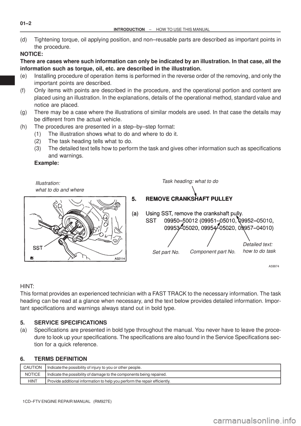
Example:
Page 2 of 136

Illustration:
what to do and whereTask heading: what to do
Detailed text:
how to do task
Set part No.Component part No.
A59974
01±2
± INTRODUCTIONHOW TO USE THIS MANUAL
1CD±FTV ENGINE REPAIR MANUAL (RM927E)
(d) Tightening torque, oil applying position, and non±reusable parts are described as important points in
the procedure.
NOTICE:
There are cases where such information can only be indicated by an illustration. In that case, all the
information such as torque, oil, etc. are described in the illustration.
(e) Installing procedure of operation items is performed in the reverse order of the removing, and only the
important points are described.
(f) Only items with points are described in the procedure, and the operational portion and content are
placed using an illustration. In the explanations, details of the operational method, standard value and
notice are placed.
(g) There may be a case where the illustrations of similar models are used. In that case the details may
be different from the actual vehicle.
(h) The procedures are presented in a step±by±step format:
(1) The illustration shows what to do and where to do it.
(2) The task heading tells what to do.
(3) The detailed text tells how to perform the task and gives other information such as specifications
and warnings.
Example:
HINT:
This format provides an experienced technician with a FAST TRACK to the necessary information. The task
heading can be read at a glance when necessary, and the text below provides detailed information. Impor-
tant specifications and warnings always stand out in bold type.
5. SERVICE SPECIFICATIONS
(a) Specifications are presented in bold type throughout the manual. You never have to leave the proce-
dure to look up your specifications. The specifications are also found in the Service Specifications sec-
tion for a quick reference.
6. TERMS DEFINITION
CAUTIONIndicate the possibility of injury to you or other people.
NOTICEIndicate the possibility of damage to the components being repaired.
HINTProvide additional information to help you perform the repair efficiently.
Page 10 of 136

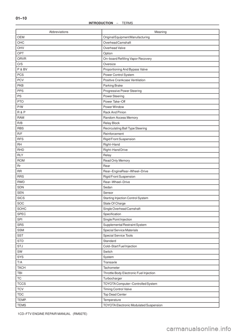
01±10
± INTRODUCTIONTERMS
1CD±FTV ENGINE REPAIR MANUAL (RM927E)Abbreviations Meaning
OEMOriginal Equipment Manufacturing
OHCOverhead Camshaft
OHVOverhead Valve
OPTOption
ORVROn±board Refilling Vapor Recovery
O/SOversize
P & BVProportioning And Bypass Valve
PCSPower Control System
PCVPositive Crankcase Ventilation
PKBParking Brake
PPSProgressive Power Steering
PSPower Steering
PTOPower Take±Off
P/WPower Window
R & PRack And Pinion
RAMRandom Access Memory
R/BRelay Block
RBSRecirculating Ball Type Steering
R/FReinforcement
RFSRigid Front Suspension
RHRight±Hand
RHDRight±Hand Drive
RLYRelay
ROMRead Only Memory
RrRear
RRRear±Engine Rear±Wheel±Drive
RRSRigid Front Suspension
RWDRear±Wheel±Drive
SDNSedan
SENSensor
SICSStarting Injection Control System
SOCState Of Charge
SOHCSingle Overhead Camshaft
SPECSpecification
SPISingle Point Injection
SRSSupplemental Restraint System
SSMSpecial Service Materials
SSTSpecial Service Tools
STDStandard
STJCold±Start Fuel Injection
SWSwitch
SYSSystem
T/ATransaxle
TACHTachometer
TBIThrottle Body Electronic Fuel Injection
TCTurbocharger
TCCSTOYOTA Computer±Controlled System
TCVTiming Control Valve
TDCTop Dead Center
TEMP.Temperature
TEMSTOYOTA Electronic Modulated Suspension
Page 13 of 136

± INTRODUCTIONTERMS
01±13
1CD±FTV ENGINE REPAIR MANUAL (RM927E) HO2S
Heated Oxygen SensorHeated Oxygen Sensor (HO2S)
IACIdle Air ControlIdle Speed Control (ISC)
IATIntake Air TemperatureIntake or Inlet Air Temperature
ICMIgnition Control Module±
IFIIndirect Fuel InjectionIndirect Injection (IDL)
IFSInertia Fuel±Shutoff±
ISCIdle Speed Control±
KSKnock SensorKnock Sensor
MAFMass Air FlowAir Flow Meter
MAPManifold Absolute PressureManifold Pressure
Intake Vacuum
MCMixture Control
Electric Bleed Air Control Valve (EBCV)
Mixture Control Valve (MCV)
Electric Air Control Valve (EACV)
MDPManifold Differential Pressure±
MFIMultiport Fuel InjectionElectronic Fuel Injection (EFI)
MILMalfunction Indicator LampCheck Engine Lamp
MSTManifold Surface Temperature±
MVZManifold Vacuum Zone±
NVRAMNon±Volatile Random Access Memory±
O2SOxygen SensorOxygen Sensor, O2 Sensor (O2S)
OBDOn±Board DiagnosticOn±Board Diagnostic System (OBD)
OCOxidation Catalytic ConverterOxidation Catalyst Convert (OC), CCo
OPOpen LoopOpen Loop
PAIRPulsed Secondary Air InjectionAir Suction (AS)
PCMPowertrain Control Module±
PNPPark/Neutral Position±
PROMProgrammable Read Only Memory±
PSPPower Steering Pressure±
PTOXPeriodic Trap OxidizerDiesel Particulate Filter (DPF)
Diesel Particulate Trap (DPT)
RAMRandom Access MemoryRandom Access Memory (RAM)
RMRelay Module±
ROMRead Only MemoryRead Only Memory (ROM)
RPMEngine SpeedEngine Speed
SCSuperchargerSupercharger
SCBSupercharger BypassE±ABV
SFISequential Multiport Fuel InjectionElectronic Fuel Injection (EFI), Sequential Injection
SPLSmoke Puff Limiter±
SRIService Reminder Indicator±
SRTSystem Readiness Test±
STScan Tool±
TBThrottle BodyThrottle Body
TBIThrottle Body Fuel InjectionSingle Point Injection
Central Fuel Injection (Ci)
TCTurbochargerTurbocharger
TCCTorque Converter ClutchTorque Converter
Page 22 of 136
030KP±01
4
5
6
7
8
9
10
11
B06431
Bolt Type
Hexagon Head Bolt
Normal Recess Bolt Deep Recess BoltStud Bolt Weld BoltClass
4T
5T
6T
7T
8T
9T
10T
11 T
No Mark
w/ WasherNo MarkNo Mark
w/ Washer
± SERVICE SPECIFICATIONSSTANDARD BOLT
03±1
1CD±FTV ENGINE REPAIR MANUAL (RM927E)
STANDARD BOLT
HOW TO DETERMINE BOLT STRENGTH
Page 23 of 136

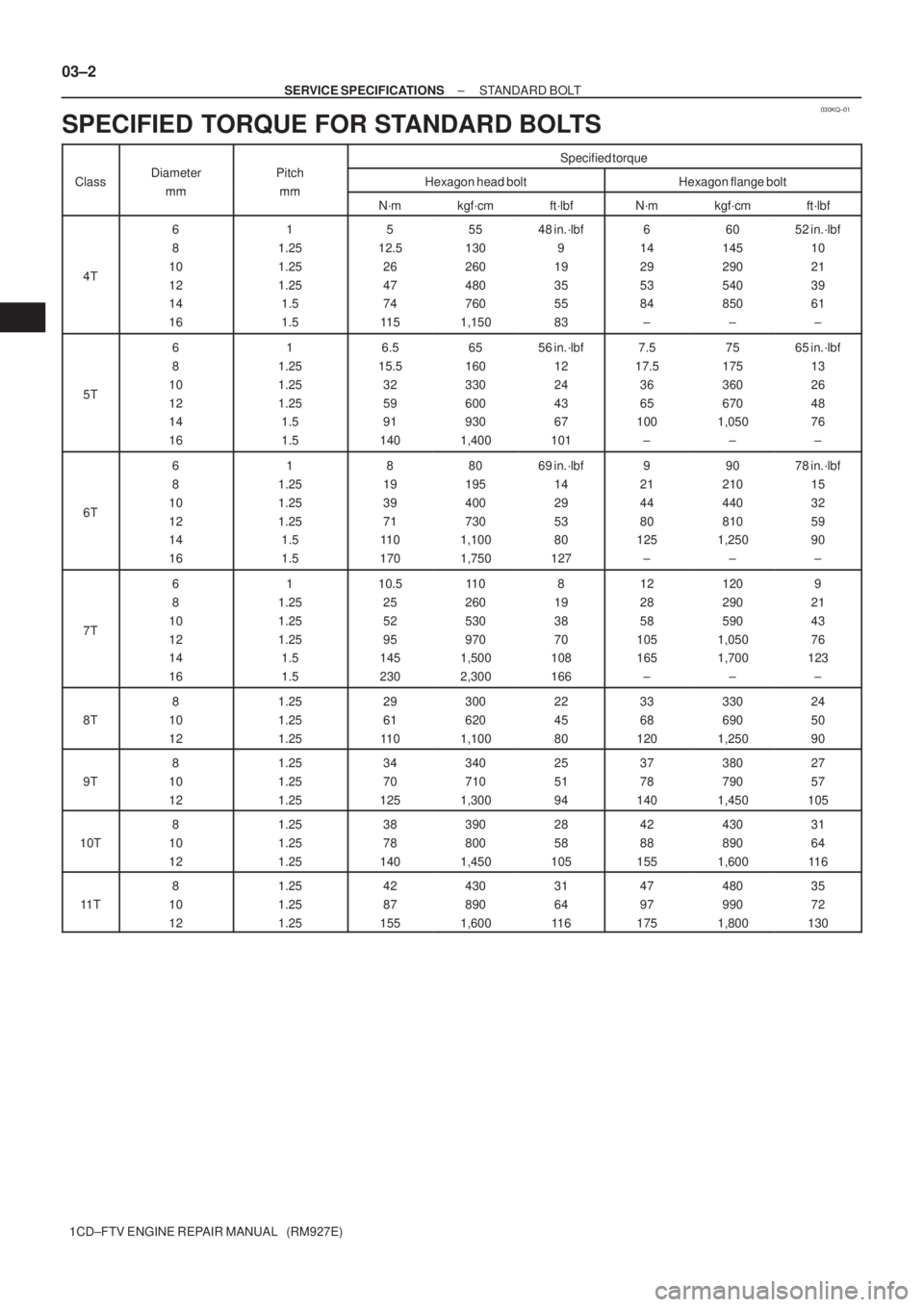
030KQ±01
03±2
± SERVICE SPECIFICATIONSSTANDARD BOLT
1CD±FTV ENGINE REPAIR MANUAL (RM927E)
SPECIFIED TORQUE FOR STANDARD BOLTS
Specified torque
ClassDiameter
mm
Pitch
mmHexagon head boltHexagon flange boltmmmmN´mkgf´cmft´lbfN´mkgf´cmft´lbf
4T
6
8
10
12
14
161
1.25
1.25
1.25
1.5
1.55
12.5
26
47
74
11 555
130
260
480
760
1,15048 in.´lbf
9
19
35
55
836
14
29
53
84
±60
145
290
540
850
±52 in.´lbf
10
21
39
61
±
5T
6
8
10
12
14
161
1.25
1.25
1.25
1.5
1.56.5
15.5
32
59
91
14065
160
330
600
930
1,40056 in.´lbf
12
24
43
67
1017.5
17.5
36
65
100
±75
175
360
670
1,050
±65 in.´lbf
13
26
48
76
±
6T
6
8
10
12
14
161
1.25
1.25
1.25
1.5
1.58
19
39
71
11 0
17080
195
400
730
1,100
1,75069 in.´lbf
14
29
53
80
1279
21
44
80
125
±90
210
440
810
1,250
±78 in.´lbf
15
32
59
90
±
7T
6
8
10
12
14
161
1.25
1.25
1.25
1.5
1.510.5
25
52
95
145
23011 0
260
530
970
1,500
2,3008
19
38
70
108
16612
28
58
105
165
±120
290
590
1,050
1,700
±9
21
43
76
123
±
8T
8
10
121.25
1.25
1.2529
61
11 0300
620
1,10022
45
8033
68
120330
690
1,25024
50
90
9T
8
10
121.25
1.25
1.2534
70
125340
710
1,30025
51
9437
78
140380
790
1,45027
57
105
10T
8
10
121.25
1.25
1.2538
78
140390
800
1,45028
58
10542
88
155430
890
1,60031
64
11 6
11 T
8
10
121.25
1.25
1.2542
87
155430
890
1,60031
64
11 647
97
175480
990
1,80035
72
130
Page 24 of 136
030KR±01
6N
8N
10N
11 N
12N
B06432
Nut Type
Present Standard
Hexagon Nut
Cold Forging Nut Cutting Processed NutClass
4N
5N (4T)
6N
7N (5T)
8N
10N (7T)
11 N
12N Old Standard Hexagon Nut
No Mark (w/ Washer)No Mark
*
No Mark (w/ Washer)
No Mark
No Mark
*: Nut with 1 or more marks on one side surface of the nut.
± SERVICE SPECIFICATIONSSTANDARD BOLT
03±3
1CD±FTV ENGINE REPAIR MANUAL (RM927E)
HOW TO DETERMINE NUT STRENGTH
HINT:
Use the nut with the same number of the nut strength classification or the greater than the bolt strength clas-
sification number when tightening parts with a bolt and nut.
Example: Bolt = 4T
Nut = 4N or more
Page 25 of 136
030KS±01
03±4
± SERVICE SPECIFICATIONSINTAKE
1CD±FTV ENGINE REPAIR MANUAL (RM927E)
INTAKE
SERVICE DATA
TurbochargerActuator pressure
Turbine wheel axial play Maximum
Turbine wheel radial play Maximum129 ± 140 kPa (1.32 ± 1.43 kgf/cm2, 18.7 ± 20.3 psi)
0.09 mm (0.0035 in.) or less
0.16 mm (0.0063 in.) or less