Page 35 of 136

A62445
Torx Socket Wrench
A62446
Matchmarks
A62447
A62448
Matchmarks
± INTAKETURBOCHARGER ASSEMBLY (1CD±FTV)
13±3
1CD±FTV ENGINE REPAIR MANUAL (RM927E)
(e) Move the actuator push rod, and check that the waste
gate valve is open.
If operation is not as specified, replace the actuator and/or tur-
bine housing.
NOTICE:
Never apply more than 161 kPa (1.64 kgf/cm
2, 28.5 psi) of
pressure on the actuator.
(f) Reconnect the actuator hose to the compressor housing.
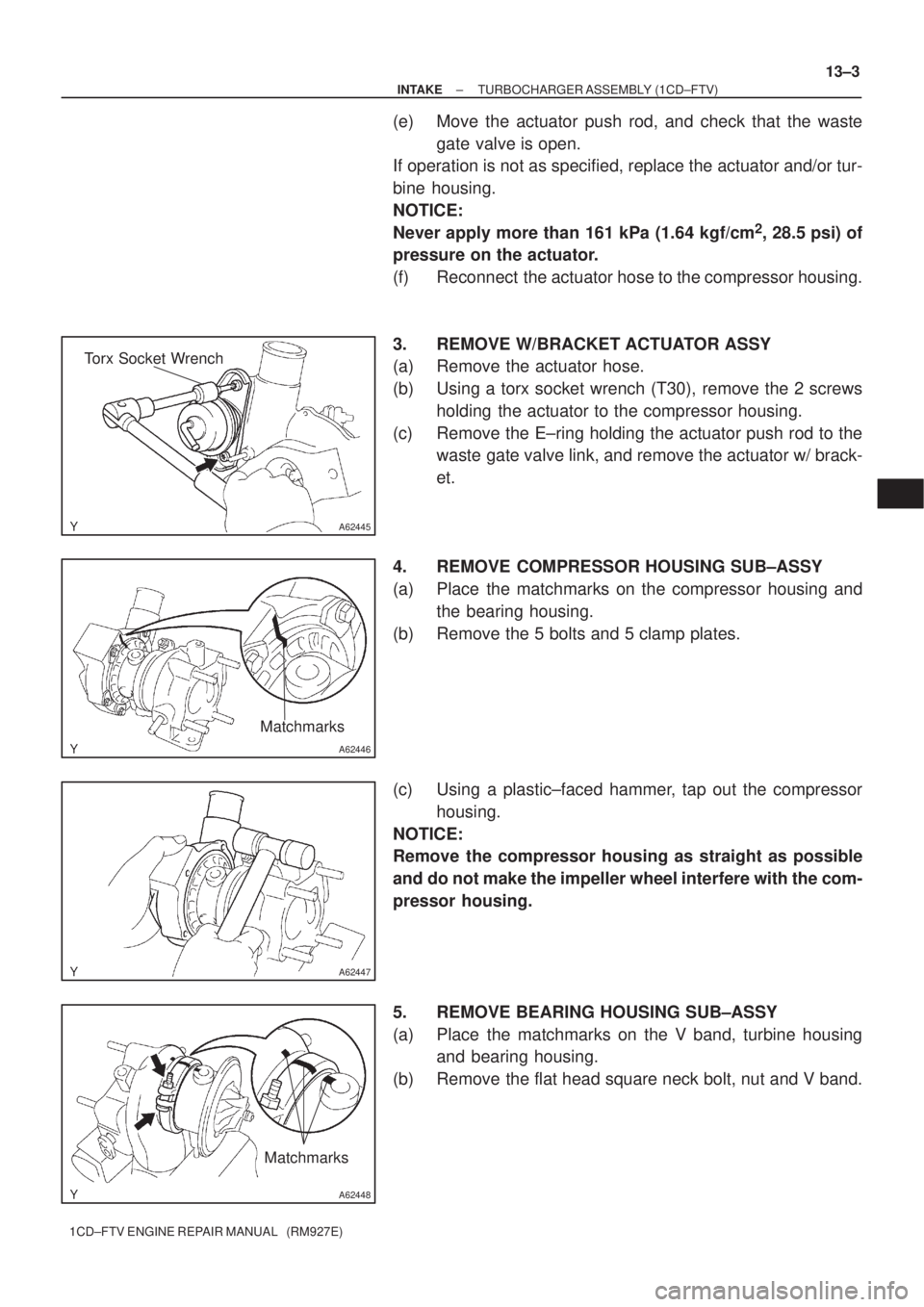
3. REMOVE W/BRACKET ACTUATOR ASSY
(a) Remove the actuator hose.
(b) Using a torx socket wrench (T30), remove the 2 screws
holding the actuator to the compressor housing.
(c) Remove the E±ring holding the actuator push rod to the
waste gate valve link, and remove the actuator w/ brack-
et.
4. REMOVE COMPRESSOR HOUSING SUB±ASSY
(a) Place the matchmarks on the compressor housing and
the bearing housing.
(b) Remove the 5 bolts and 5 clamp plates.
(c) Using a plastic±faced hammer, tap out the compressor
housing.
NOTICE:
Remove the compressor housing as straight as possible
and do not make the impeller wheel interfere with the com-
pressor housing.
5. REMOVE BEARING HOUSING SUB±ASSY
(a) Place the matchmarks on the V band, turbine housing
and bearing housing.
(b) Remove the flat head square neck bolt, nut and V band.
Page 38 of 136

A62451
A62452
A62960
Old V Band
New V Band
Matchmark
13±6
± INTAKETURBOCHARGER ASSEMBLY (1CD±FTV)
1CD±FTV ENGINE REPAIR MANUAL (RM927E)
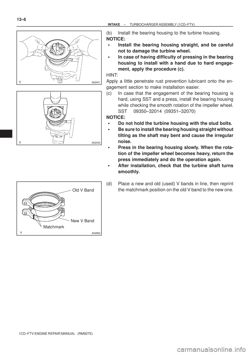
(b) Install the bearing housing to the turbine housing.
NOTICE:
�Install the bearing housing straight, and be careful
not to damage the turbine wheel.
�In case of having difficulty of pressing in the bearing
housing to install with a hand due to hard engage-
ment, apply the procedure (c).
HINT:
Apply a little penetrate rust prevention lubricant onto the en-
gagement section to make installation easier.
(c) In case that the engagement of the bearing housing is
hard, using SST and a press, install the bearing housing
while checking the smooth rotation of the impeller wheel.
SST 09350±32014 (09351±32070)
NOTICE:
�Do not hold the turbine housing with the stud bolts.
�Be sure to install the bearing housing straight without
tilting as the shaft may bent and cause the irregular
noise.
�Press in the bearing housing slowly. When the rota-
tion of the impeller wheel becomes heavy, return the
press immediately and do the operation again.
�After installation, check that the turbine shaft turns
smoothly.
(d) Place a new and old (used) V bands in line, then reprint
the matchmark position on the old V band to the new one.
Page 40 of 136

A62455
Matchmarks
A62456
Cut
Protractor
Steel Square49�
A62457
SST
13±8
± INTAKETURBOCHARGER ASSEMBLY (1CD±FTV)
1CD±FTV ENGINE REPAIR MANUAL (RM927E)
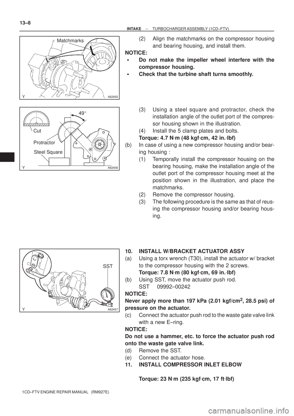
(2) Align the matchmarks on the compressor housing
and bearing housing, and install them.
NOTICE:
�Do not make the impeller wheel interfere with the
compressor housing.
�Check that the turbine shaft turns smoothly.
(3) Using a steel square and protractor, check the
installation angle of the outlet port of the compres-
sor housing shown in the illustration.
(4) Install the 5 clamp plates and bolts.
Torque: 4.7 N�m (48 kgf�cm, 42 in.�lbf)
(b) In case of using a new compressor housing and/or bear-
ing housing :
(1) Temporally install the compressor housing on the
bearing housing, make the installation angle of the
outlet port of the compressor housing meet at the
position shown in the illustration, and place the
matchmarks.
(2) Remove the compressor housing.
(3) The following procedure is the same as that of reus-
ing the compressor housing and/or bearing hous-
ing.
10. INSTALL W/BRACKET ACTUATOR ASSY
(a) Using a torx wrench (T30), install the actuator w/ bracket
to the compressor housing with the 2 screws.
Torque: 7.8 N�m (80 kgf�cm, 69 in.�lbf)
(b) Using SST, move the actuator push rod.
SST 09992±00242
NOTICE:
Never apply more than 197 kPa (2.01 kgf/cm
2, 28.5 psi) of
pressure on the actuator.
(c) Connect the actuator push rod to the waste gate valve link
with a new E±ring.
NOTICE:
Do not use a hammer, etc. to force the actuator push rod
onto the waste gate valve link.
(d) Remove the SST.
(e) Connect the actuator hose.
11. INSTALL COMPRESSOR INLET ELBOW
Torque: 23 N�m (235 kgf�cm, 17 ft�lbf)