Page 7 of 136

010B9±02
± INTRODUCTIONTERMS
01±7
1CD±FTV ENGINE REPAIR MANUAL (RM927E)
TERMS
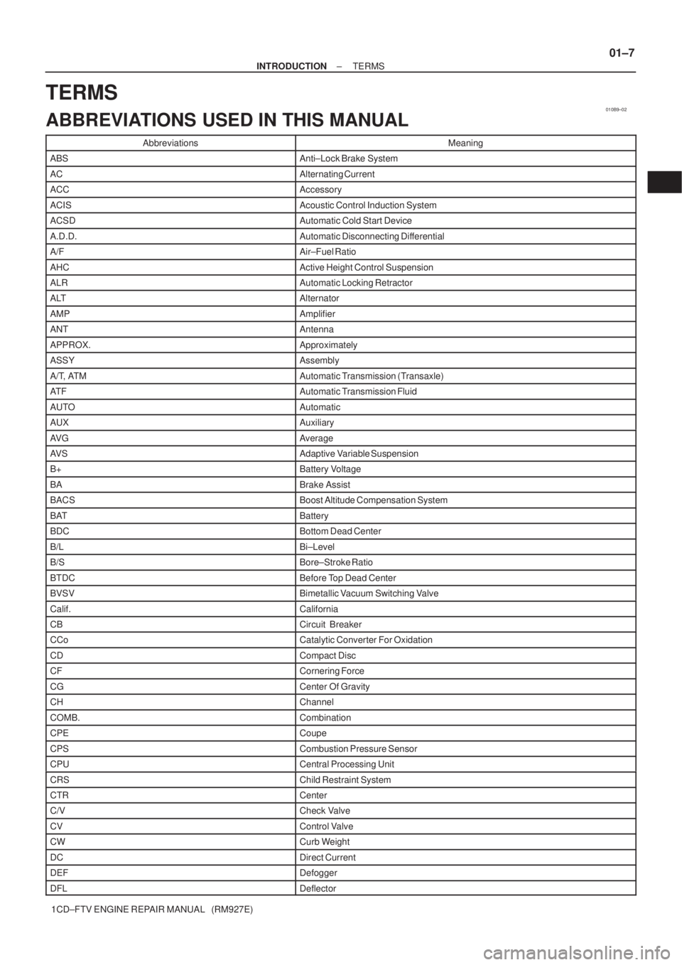
ABBREVIATIONS USED IN THIS MANUAL
AbbreviationsMeaning
ABSAnti±Lock Brake System
ACAlternating Current
ACCAccessory
ACISAcoustic Control Induction System
ACSDAutomatic Cold Start Device
A.D.D.Automatic Disconnecting Differential
A/FAir±Fuel Ratio
AHCActive Height Control Suspension
ALRAutomatic Locking Retractor
ALTAlternator
AMPAmplifier
ANTAntenna
APPROX.Approximately
ASSYAssembly
A/T, ATMAutomatic Transmission (Transaxle)
AT FAutomatic Transmission Fluid
AUTOAutomatic
AUXAuxiliary
AV GAverage
AV SAdaptive Variable Suspension
B+Battery Voltage
BABrake Assist
BACSBoost Altitude Compensation System
BATBattery
BDCBottom Dead Center
B/LBi±Level
B/SBore±Stroke Ratio
BTDCBefore Top Dead Center
BVSVBimetallic Vacuum Switching Valve
Calif.California
CBCircuit Breaker
CCoCatalytic Converter For Oxidation
CDCompact Disc
CFCornering Force
CGCenter Of Gravity
CHChannel
COMB.Combination
CPECoupe
CPSCombustion Pressure Sensor
CPUCentral Processing Unit
CRSChild Restraint System
CTRCenter
C/VCheck Valve
CVControl Valve
CWCurb Weight
DCDirect Current
DEFDefogger
DFLDeflector
Page 12 of 136

010BA±03
01±12
± INTRODUCTIONTERMS
1CD±FTV ENGINE REPAIR MANUAL (RM927E)
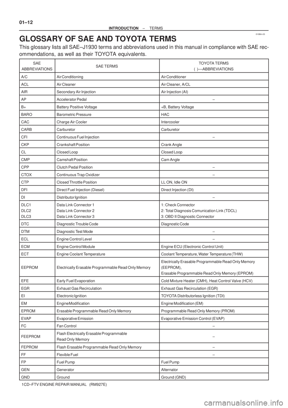
GLOSSARY OF SAE AND TOYOTA TERMS
This glossary lists all SAE±J1930 terms and abbreviations used in this manual in compliance with SAE rec-
ommendations, as well as their TOYOTA equivalents.
SAE
ABBREVIATIONSSAE TERMSTOYOTA TERMS
( )±±ABBREVIATIONS
A/CAir ConditioningAir Conditioner
ACLAir CleanerAir Cleaner, A/CL
AIRSecondary Air InjectionAir Injection (AI)
APAccelerator Pedal±
B+Battery Positive Voltage+B, Battery Voltage
BAROBarometric PressureHAC
CACCharge Air CoolerIntercooler
CARBCarburetorCarburetor
CFIContinuous Fuel Injection±
CKPCrankshaft PositionCrank Angle
CLClosed LoopClosed Loop
CMPCamshaft PositionCam Angle
CPPClutch Pedal Position±
CTOXContinuous Trap Oxidizer±
CTPClosed Throttle PositionLL ON, Idle ON
DFIDirect Fuel Injection (Diesel)Direct Injection (DI)
DIDistributor Ignition±
DLC1
DLC2
DLC3Data Link Connector 1
Data Link Connector 2
Data Link Connector 31: Check Connector
2: Total Diagnosis Comunication Link (TDCL)
3: OBD II Diagnostic Connector
DTCDiagnostic Trouble CodeDiagnostic Code
DTMDiagnostic Test Mode±
ECLEngine Control Level±
ECMEngine Control ModuleEngine ECU (Electronic Control Unit)
ECTEngine Coolant TemperatureCoolant Temperature, Water Temperature (THW)
EEPROMElectrically Erasable Programmable Read Only Memory
Electrically Erasable Programmable Read Only Memory
(EEPROM),
Erasable Programmable Read Only Memory (EPROM)
EFEEarly Fuel EvaporationCold Mixture Heater (CMH), Heat Control Valve (HCV)
EGRExhaust Gas RecirculationExhaust Gas Recirculation (EGR)
EIElectronic IgnitionTOYOTA Distributorless Ignition (TDI)
EMEngine ModificationEngine Modification (EM)
EPROMErasable Programmable Read Only MemoryProgrammable Read Only Memory (PROM)
EVAPEvaporative EmissionEvaporative Emission Control (EVAP)
FCFan Control±
FEEPROMFlash Electrically Erasable Programmable
Read Only Memory±
FEPROMFlash Erasable Programmable Read Only Memory±
FFFlexible Fuel±
FPFuel PumpFuel Pump
GENGeneratorAlternator
GNDGroundGround (GND)
Page 20 of 136
0214U±01
02±6
± PREPARATIONSTARTING & CHARGING
1CD±FTV ENGINE REPAIR MANUAL (RM927E)
STARTING & CHARGING
PREPARATION
SST
09820±63020Alternator Pulley Wrench SetGENERATOR
ASSY(130A)(1CD±FTV)
09950±40011Puller B SetGENERATOR
ASSY(130A)(1CD±FTV)
(09951±04020)Hanger 200GENERATOR
ASSY(130A)(1CD±FTV)
(09952±04010)Slide ArmGENERATOR
ASSY(130A)(1CD±FTV)
(09953±04020)Center Bolt 150GENERATOR
ASSY(130A)(1CD±FTV)
(09954±04010)Arm 25GENERATOR
ASSY(130A)(1CD±FTV)
(09955±04071)Claw No.7GENERATOR
ASSY(130A)(1CD±FTV)
(09958±04011)HolderGENERATOR
ASSY(130A)(1CD±FTV)
09950±60010Replacer SetSTARTER ASSY(2.0KW)(1CD±FTV)
(09951±00340)Replacer 34STARTER ASSY(2.0KW)(1CD±FTV)
Recomended Tools
09082±00040TOYOTA Electrical TesterSTARTER ASSY(1.4KW)(1CD±FTV)
STARTER ASSY(2.2KW)(1CD±FTV)
GENERATOR
ASSY(130A)(1CD±FTV)
(09083±00150)Test Lead SetSTARTER ASSY(1.4KW)(1CD±FTV)
STARTER ASSY(2.2KW)(1CD±FTV)
GENERATOR ASSY(90A)(1CD±FTV)
GENERATOR
ASSY(130A)(1CD±FTV)
Page 125 of 136
19094±02
A59147
PulleyDrive End FrameRotor
Alternator Washer
Rectifier End Frame
Voltage Regulator Brush Holder Cover
Brush HolderRear End Cover
N´m (kgf´cm, ft´lbf)
: Specified torque
111 (1125, 81)
Rectifier Holder
19±24
± STARTING & CHARGINGGENERATOR ASSY(90A) (1CD±FTV)
1CD±FTV ENGINE REPAIR MANUAL (RM927E)
GENERATOR ASSY(90A) (1CD±FTV)
COMPONENTS
Page 126 of 136
19095±02
A38024
A38025
SST 1 ± A
A38104
A38105
± STARTING & CHARGINGGENERATOR ASSY(90A) (1CD±FTV)
19±25
1CD±FTV ENGINE REPAIR MANUAL (RM927E)
OVERHAUL
1. REMOVE GENERATOR PULLEY
SST 09820±63010 (09820±06010, 09820±06020)
HINT:
SST1 ± A, B09820±06010
SST209820±06020
(a) Hold SST 1 ± A with a torque wrench, and tighten SST 1
± B clockwise to the specified torque.
Torque: 39 N�m (400 kgf�cm, 29 ft�lbf)
NOTICE:
Check that SST is secured to the rotor shaft.
(b) Mount SST 2 in a vise.
(c) Insert SST 1 ± A, B into SST 2, and attach the pulley nut
to SST 2.
(d) To loosen the pulley nut, turn SST 1 ± A in the direction
shown in the illustration.
NOTICE:
To prevent damage to the rotor shaft, do not loosen the
pulley nut more than one±half of a turn.
(e) Remove the alternator form SST 2.
(f) Turn SST 1 ± B, and remove SST 1 ± A, B.
(g) Remove the pulley nut and pulley.
Page 127 of 136

SST
Wooden block
A51918
A59143
F
B
Ohmmeter 19±26
± STARTING & CHARGINGGENERATOR ASSY(90A) (1CD±FTV)
1CD±FTV ENGINE REPAIR MANUAL (RM927E)
2. REMOVE GENERATOR BRUSH HOLDER ASSY
(a) Remove the nut and terminal insulator.
(b) Remove the bolt, 3 nuts, plate terminal and end cover.
(c) Remove the brush cover.
(d) Remove the 2 screws and brush holder.
3. REMOVE GENERATOR REGULATOR ASSY
(a) Remove the 3 screws and voltage regulator.
4. REMOVE GENERATOR HOLDER W/RECTIFIER
(a) Remove the 4 screws and rectifier holder.
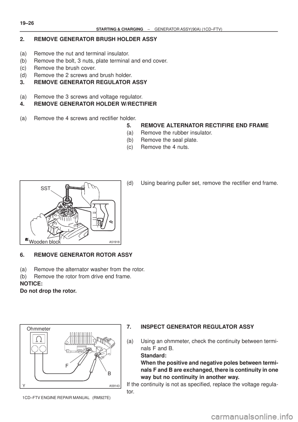
5. REMOVE ALTERNATOR RECTIFIRE END FRAME
(a) Remove the rubber insulator.
(b) Remove the seal plate.
(c) Remove the 4 nuts.
(d) Using bearing puller set, remove the rectifier end frame.
6. REMOVE GENERATOR ROTOR ASSY
(a) Remove the alternator washer from the rotor.
(b) Remove the rotor from drive end frame.
NOTICE:
Do not drop the rotor.
7. INSPECT GENERATOR REGULATOR ASSY
(a) Using an ohmmeter, check the continuity between termi-
nals F and B.
Standard:
When the positive and negative poles between termi-
nals F and B are exchanged, there is continuity in one
way but no continuity in another way.
If the continuity is not as specified, replace the voltage regula-
tor.
Page 129 of 136

Length
P13535
17 mm
Socket
Wrench
A51920
Cord ClipA
B
A A
A64533
Inside
A51921
19±28
± STARTING & CHARGINGGENERATOR ASSY(90A) (1CD±FTV)
1CD±FTV ENGINE REPAIR MANUAL (RM927E)
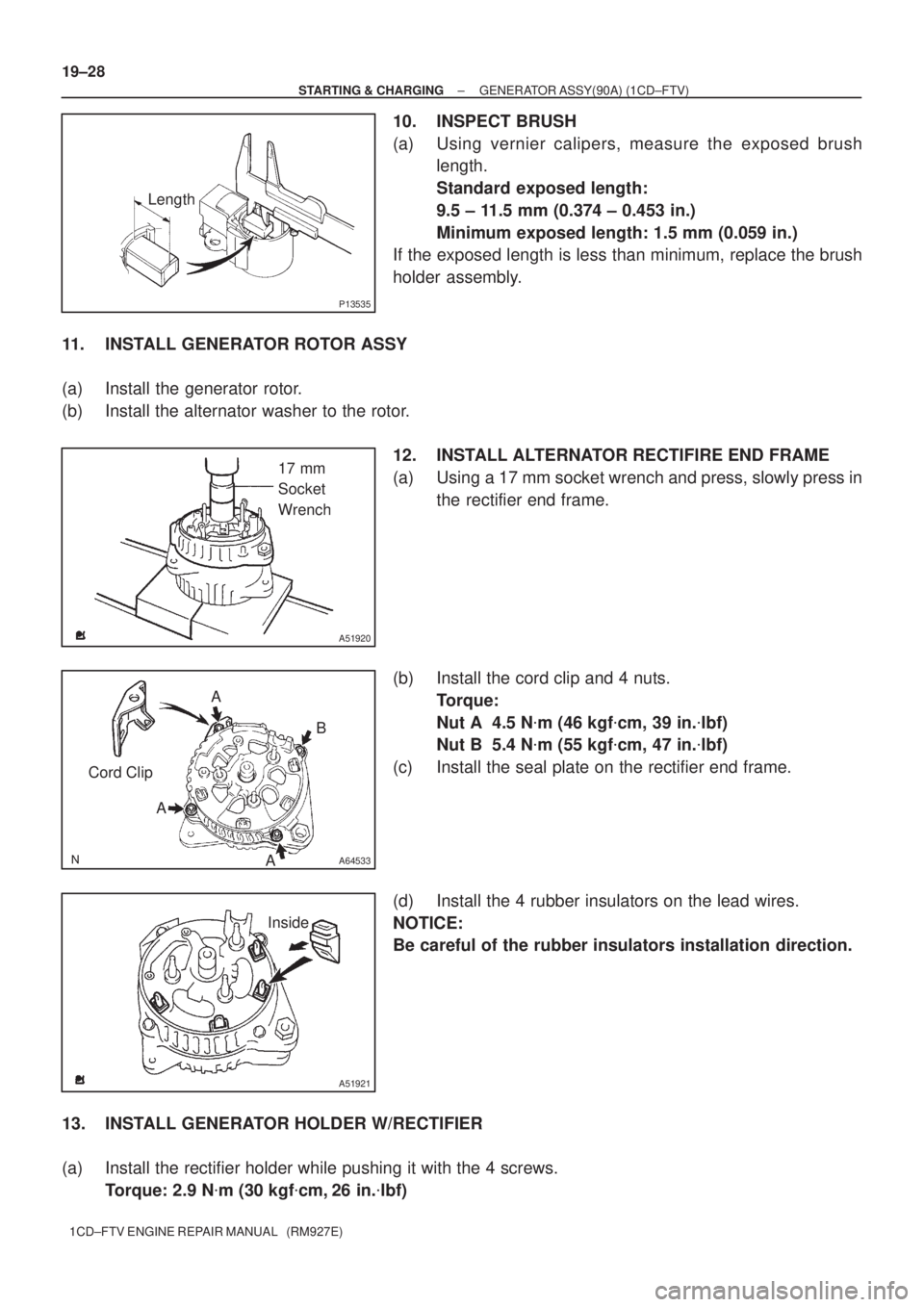
10. INSPECT BRUSH
(a) Using vernier calipers, measure the exposed brush
length.
Standard exposed length:
9.5 ± 11.5 mm (0.374 ± 0.453 in.)
Minimum exposed length: 1.5 mm (0.059 in.)
If the exposed length is less than minimum, replace the brush
holder assembly.
11. INSTALL GENERATOR ROTOR ASSY
(a) Install the generator rotor.
(b) Install the alternator washer to the rotor.
12. INSTALL ALTERNATOR RECTIFIRE END FRAME
(a) Using a 17 mm socket wrench and press, slowly press in
the rectifier end frame.
(b) Install the cord clip and 4 nuts.
Torque:
Nut A 4.5 N�m (46 kgf�cm, 39 in.�lbf)
Nut B 5.4 N�m (55 kgf�cm, 47 in.�lbf)
(c) Install the seal plate on the rectifier end frame.
(d) Install the 4 rubber insulators on the lead wires.
NOTICE:
Be careful of the rubber insulators installation direction.
13. INSTALL GENERATOR HOLDER W/RECTIFIER
(a) Install the rectifier holder while pushing it with the 4 screws.
Torque: 2.9 N�m (30 kgf�cm, 26 in.�lbf)
Page 131 of 136
A38025
SST 1 ± A
A38126
A38105
19±30
± STARTING & CHARGINGGENERATOR ASSY(90A) (1CD±FTV)
1CD±FTV ENGINE REPAIR MANUAL (RM927E)
(c) Mount SST 2 in a vise.
(d) Insert SST 1 ± A, B into SST 2, and attach the pulley nut
to SST 2.
(e) Tighten the pulley nut, turn SST 1 ± A in the direction
shown in the illustration.
Torque: 111 N�m (1,125 kgf�cm, 81 ft�lbf)
(f) Remove the alternator form SST 2.
(g) Turn SST 1 ± B, and remove SST 1 ± A, B.
(h) Turn the pulley, and check that the pulley moves smooth-
ly.