Page 12 of 136

GLOSSARY OF SAE AND TOYOTA TERMS
This glossary lists all SAE±J1930 terms and abbreviations used in this manual in compli")
010BA±03
01±12
± INTRODUCTIONTERMS
1CD±FTV ENGINE REPAIR MANUAL (RM927E)
GLOSSARY OF SAE AND TOYOTA TERMS
This glossary lists all SAE±J1930 terms and abbreviations used in this manual in compliance with SAE rec-
ommendations, as well as their TOYOTA equivalents.
SAE
ABBREVIATIONSSAE TERMSTOYOTA TERMS
( )±±ABBREVIATIONS
A/CAir ConditioningAir Conditioner
ACLAir CleanerAir Cleaner, A/CL
AIRSecondary Air InjectionAir Injection (AI)
APAccelerator Pedal±
B+Battery Positive Voltage+B, Battery Voltage
BAROBarometric PressureHAC
CACCharge Air CoolerIntercooler
CARBCarburetorCarburetor
CFIContinuous Fuel Injection±
CKPCrankshaft PositionCrank Angle
CLClosed LoopClosed Loop
CMPCamshaft PositionCam Angle
CPPClutch Pedal Position±
CTOXContinuous Trap Oxidizer±
CTPClosed Throttle PositionLL ON, Idle ON
DFIDirect Fuel Injection (Diesel)Direct Injection (DI)
DIDistributor Ignition±
DLC1
DLC2
DLC3Data Link Connector 1
Data Link Connector 2
Data Link Connector 31: Check Connector
2: Total Diagnosis Comunication Link (TDCL)
3: OBD II Diagnostic Connector
DTCDiagnostic Trouble CodeDiagnostic Code
DTMDiagnostic Test Mode±
ECLEngine Control Level±
ECMEngine Control ModuleEngine ECU (Electronic Control Unit)
ECTEngine Coolant TemperatureCoolant Temperature, Water Temperature (THW)
EEPROMElectrically Erasable Programmable Read Only Memory
Electrically Erasable Programmable Read Only Memory
(EEPROM),
Erasable Programmable Read Only Memory (EPROM)
EFEEarly Fuel EvaporationCold Mixture Heater (CMH), Heat Control Valve (HCV)
EGRExhaust Gas RecirculationExhaust Gas Recirculation (EGR)
EIElectronic IgnitionTOYOTA Distributorless Ignition (TDI)
EMEngine ModificationEngine Modification (EM)
EPROMErasable Programmable Read Only MemoryProgrammable Read Only Memory (PROM)
EVAPEvaporative EmissionEvaporative Emission Control (EVAP)
FCFan Control±
FEEPROMFlash Electrically Erasable Programmable
Read Only Memory±
FEPROMFlash Erasable Programmable Read Only Memory±
FFFlexible Fuel±
FPFuel PumpFuel Pump
GENGeneratorAlternator
GNDGroundGround (GND)
Page 29 of 136

TORQUE SPECIFICATION
Part TightenedN �mkgf �cmft �lbf
Cylinder block water drain cock x Cylinder bl")
0300P±05
03±8
±
SERVICE SPECIFICATIONS ENGINE MECHANICAL
1CD±FTV ENGINE REPAIR MANUAL (RM927E)
TORQUE SPECIFICATION
Part TightenedN �mkgf �cmft �lbf
Cylinder block water drain cock x Cylinder block2929121
Oil check valve x Cylinder block3031022
Oil pump x Cylinder block3132023
Oil pan x Cylinder block For 10 mm head bolt and nut
For 12 mm head bolt
For 14 mm head bolt11
21
4211 2
210
4298.0 15
31
Oil strainer x Cylinder block For bolt For nut21
13210
13515
10
Oil pan No.2 x Cylinder block121209.0
Cylinder head x Cylinder block 1st 2nd3rd
4th45
Turn 90 �
Turn 90 �
Turn 90 �460
Turn 90 �
Turn 90 �
Turn 90 �33
Turn 90 �
Turn 90 �
Turn 90 �
Camshaft bearing cap x Cylinder head2020415
Water pump x Cylinder block3132023
Camshaft oil seal retainer x Cylinder head8.89078 in.�lbf
Timing belt idler Sub assy No.2 x Oil pump4747534
Timing belt idler No. 1 x Cylinder head3535025
Camshaft timing pulley x Camshaft8889965
Nozzle holder clamp x Cylinder head2727520
Nozzle leakage pipe x Cylinder head Hollow screw
Union bolt18
22184
22413
16
Over flow screw x Plug9.81007.0
Check valve x Cylinder head2121415
Cylinder head cover x Cylinder head1313510
Taper screw plug No.1 x Cylinder head2525518
Cylinder head stud bolt (See Page 14±23) Bolt A Bolt B
Bolt C8.8
12
8.890
120 9078 in. �lbf
9.0
78 in. �lbf
Connecting rod cap x Connecting rod 1st
2nd30
Turn 90 �306
Turn 90 �22
Turn 90 �
Crankshaft bearing cap x Cylinder block11 51,17385
Cylinder block oil orifice x Cylinder block9.09278 in.�lbf
Oil nozzle No.1 x Cylinder block7.47667 in. �lbf
Page 42 of 136
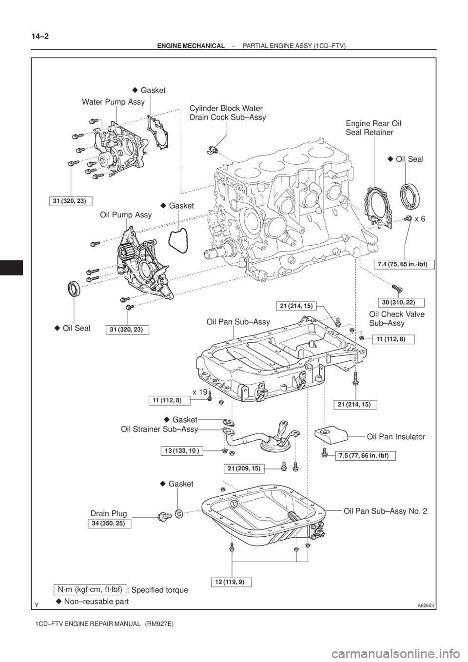
A62603
Engine Rear Oil
Seal Retainer
Oil Check Valve
Sub±Assy
Cylinder Block Water
Drain Cock Sub±Assy
31 (320, 23)
Water Pump Assy
21 (209, 15)
� Gasket � Gasket
x 6
� Gasket
� Oil Seal
Oil Pump Assy
� Oil Seal31 (320, 23)
7.4 (75, 65 in.´lbf)
11 (112, 8)
21 (214, 15)
Oil Pan Sub±Assy
11 (112, 8)x 19
Oil Strainer Sub±Assy
13 (133, 10 )
34 (350, 25)
Drain Plug
� Gasket
7.5 (77, 66 in.´lbf)
Oil Pan Insulator
Oil Pan Sub±Assy No. 2
12 (119, 9)
� Non±reusable part
N´m (kgf´cm, ft´lbf)
: Specified torque
21 (214, 15)30 (310, 22)
14±2
± ENGINE MECHANICALPARTIAL ENGINE ASSY (1CD±FTV)
1CD±FTV ENGINE REPAIR MANUAL (RM927E)
Page 45 of 136
A57097
A57098
A09650
1 3
24
576
8
9
10 11
12
13 14
15
A09624
± ENGINE MECHANICALPARTIAL ENGINE ASSY (1CD±FTV)
14±5
1CD±FTV ENGINE REPAIR MANUAL (RM927E)
11. REMOVE CAMSHAFT OIL SEAL RETAINER
(a) Remove the 4 bolts.
(b) Using a screwdriver, remove the oil seal retainer by prying
the portions between the oil seal retainer and camshaft
bearing cap.
12. REMOVE WATER PUMP ASSY
(a) Remove the 7 bolts, water pump and gasket.
13. REMOVE CAMSHAFT SUB±ASSY, NO.2
(a) Uniformly loosen and remove the 15 bearing cap bolts in
several passes in the sequence shown.
(b) Remove the 5 bearing caps.
(c) Remove the camshaft No. 2.
14. REMOVE CAMSHAFT SUB±ASSY, NO.1
(a) Remove the camshaft from the cylinder head.
(b) Remove the camshaft carrier from the cylinder head.
Page 48 of 136
A09619
SST
A09620
B07976
A56700
SST
14±8
± ENGINE MECHANICALPARTIAL ENGINE ASSY (1CD±FTV)
1CD±FTV ENGINE REPAIR MANUAL (RM927E)
22. REMOVE CYLINDER BLOCK WATER DRAIN COCK SUB±ASSY
23. REMOVE CAMSHAFT OIL SEAL
(a) Using a screwdriver and a hammer, tap out the oil seal.
24. INSTALL CAMSHAFT OIL SEAL
(a) Using SST and a hammer, tap in a new oil seal until its sur-
face is flush with the camshaft oil seal retainer edge.
SST 09223±46011
25. REMOVE CRANKSHAFT SEAL
(a) Using a screwdriver and a hammer, tap out the oil seal.
26. INSTALL CRANKSHAFT SEAL
(a) Using SST and a hammer, tap in a new oil seal until its sur-
face is flush with the oil pump edge.
SST 09316±60011 (09316±00011, 09316±00021)
Page 57 of 136

14±17
1CD±FTV ENGINE REPAIR MANUAL (RM927E)
42. INSTA")
A57098
A09600
Seal Width
2 ± 4 mm
Seal Packing
SST
A57101
Inward
Angle Sensor
A57102
Turn
± ENGINE MECHANICALPARTIAL ENGINE ASSY (1CD±FTV)
14±17
1CD±FTV ENGINE REPAIR MANUAL (RM927E)
42. INSTALL WATER PUMP ASSY
(a) Install a new gasket and the water pump with the 7bolts.
Torque: 31 N�m (320 kgf�cm, 23 ft�lbf)
43. INSTALL CAMSHAFT OIL SEAL RETAINER
(a) Apply seal packing to the oil seal retainer as shown in the
illustration.
Seal packing: Part No. 08826±00080 or equivalent
NOTICE:
�Install a nozzle that has been cut to a 2 ± 4 mm (0.08
± 0.16 in.) opening.
�Parts must be assembled within 15 minutes of ap-
plication. Otherwise the material must be removed
and reapplied.
�Immediately remove nozzle from the tube and rein-
stall the cap.
(b) Install the oil seal retainer with 4 bolts. Uniformly tighten
the 4 bolts in several passes.
Torque: 8.8 N�m (90 kgf�cm, 78 in.�lbf)
44. INSTALL CRANKSHAFT TIMING PULLEY
(a) Align the pulley set key with the key groove of the timing
pulley.
(b) Using SST and a hammer, tap in the timing pulley, facing
the angle sensor inward.
SST 09223±46011
45. INSTALL TIMING BELT IDLER SUB±ASSY NO.2
(a) Install the idler pulley with the bolt.
Torque: 47 N�m (475 kgf�cm, 34 ft�lbf)
(b) Check that the idler pulley moves smoothly.
Page 100 of 136
1606V±02
A55603Drain Hole
Turn
± COOLINGWATER PUMP ASSY (1CD±FTV)
16±1
1CD±FTV ENGINE REPAIR MANUAL (RM927E)
WATER PUMP ASSY (1CD±FTV)
INSPECTION
1. INSPECT WATER PUMP ASSY
(a) Visually check the drain hole for coolant leakage.
(b) Turn the pulley, and check that the water pump bearing
moves smoothly and quietly.

14±5
1CD±FTV ENGINE REPAIR MANUAL (RM927E)
11. REMOVE CAMSHAFT OIL SEAL RETAINER
(a)")

1CD±FTV ENGINE REPAIR MANUAL (RM927E)
22. REMOVE CYLINDER BLOCK WATER DRAIN COCK SUB±ASSY
23. REMOVE CA")

16±1
1CD±FTV ENGINE REPAIR MANUAL (RM927E)
WATER PUMP ASSY (1CD±FTV)
INSPECTION
1. INSPECT WATER PUMP ASSY
(a) Visually check")