Page 29 of 136
0300P±05
03±8
±
SERVICE SPECIFICATIONS ENGINE MECHANICAL
1CD±FTV ENGINE REPAIR MANUAL (RM927E)
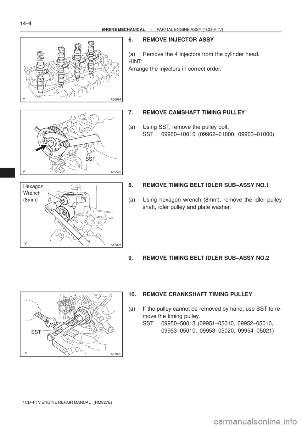
TORQUE SPECIFICATION
Part TightenedN �mkgf �cmft �lbf
Cylinder block water drain cock x Cylinder block2929121
Oil check valve x Cylinder block3031022
Oil pump x Cylinder block3132023
Oil pan x Cylinder block For 10 mm head bolt and nut
For 12 mm head bolt
For 14 mm head bolt11
21
4211 2
210
4298.0 15
31
Oil strainer x Cylinder block For bolt For nut21
13210
13515
10
Oil pan No.2 x Cylinder block121209.0
Cylinder head x Cylinder block 1st 2nd3rd
4th45
Turn 90 �
Turn 90 �
Turn 90 �460
Turn 90 �
Turn 90 �
Turn 90 �33
Turn 90 �
Turn 90 �
Turn 90 �
Camshaft bearing cap x Cylinder head2020415
Water pump x Cylinder block3132023
Camshaft oil seal retainer x Cylinder head8.89078 in.�lbf
Timing belt idler Sub assy No.2 x Oil pump4747534
Timing belt idler No. 1 x Cylinder head3535025
Camshaft timing pulley x Camshaft8889965
Nozzle holder clamp x Cylinder head2727520
Nozzle leakage pipe x Cylinder head Hollow screw
Union bolt18
22184
22413
16
Over flow screw x Plug9.81007.0
Check valve x Cylinder head2121415
Cylinder head cover x Cylinder head1313510
Taper screw plug No.1 x Cylinder head2525518
Cylinder head stud bolt (See Page 14±23) Bolt A Bolt B
Bolt C8.8
12
8.890
120 9078 in. �lbf
9.0
78 in. �lbf
Connecting rod cap x Connecting rod 1st
2nd30
Turn 90 �306
Turn 90 �22
Turn 90 �
Crankshaft bearing cap x Cylinder block11 51,17385
Cylinder block oil orifice x Cylinder block9.09278 in.�lbf
Oil nozzle No.1 x Cylinder block7.47667 in. �lbf
Page 41 of 136
140L3±01
A62602
Cylinder Head
Cover Sub±AssyGasket
Camshaft
Sub±Assy No.2
Camshaft
Sub±Assy No.1
18 (184, 13)
Camshaft Oil
Seal Retainer
� Nozzle Holder Seal
Nozzle Leakage
Pipe Assy
Nozzle Holder Clamp � O±Ring
� Injection Nozzle Seat
� Fuel Injector
Back±Up Ring No. 1
13 (135, 10)
Washer
Camshaft Carrier
Camshaft Bearing Cap
20 (204, 15)
Injector Assy
8.8 (90, 78 in.´lbf)
See page 14±3
1st 45 (460, 33)
2nd Turn 90 �
3rd Turn 90 �
4th Turn 90 �
22 (224, 16)
27 (275, 20)
� Gasket
� Gasket
20 (204, 15)
� Cylinder Head Gasket
� Oil Seal Plate Washer
x 18
Cylinder Head
Sub±Assy
�
Nozzle Holder Gasket
� Non±reusable partN´m (kgf´cm, ft´lbf)
: Specified torque
Oil Filler Cap Sub±Assy
Plate Washer
Camshaft Timing Pulley
88 (899, 65)
35 (357, 26)
Timing Belt Idler Sub±Assy No. 1
Timing Belt Idler Sub±Assy No. 2
47 (475, 34)
Crankshaft Timing Pulley
±
ENGINE MECHANICAL PARTIAL ENGINE ASSY (1CD±FTV)
14±1
1CD±FTV ENGINE REPAIR MANUAL (RM927E)
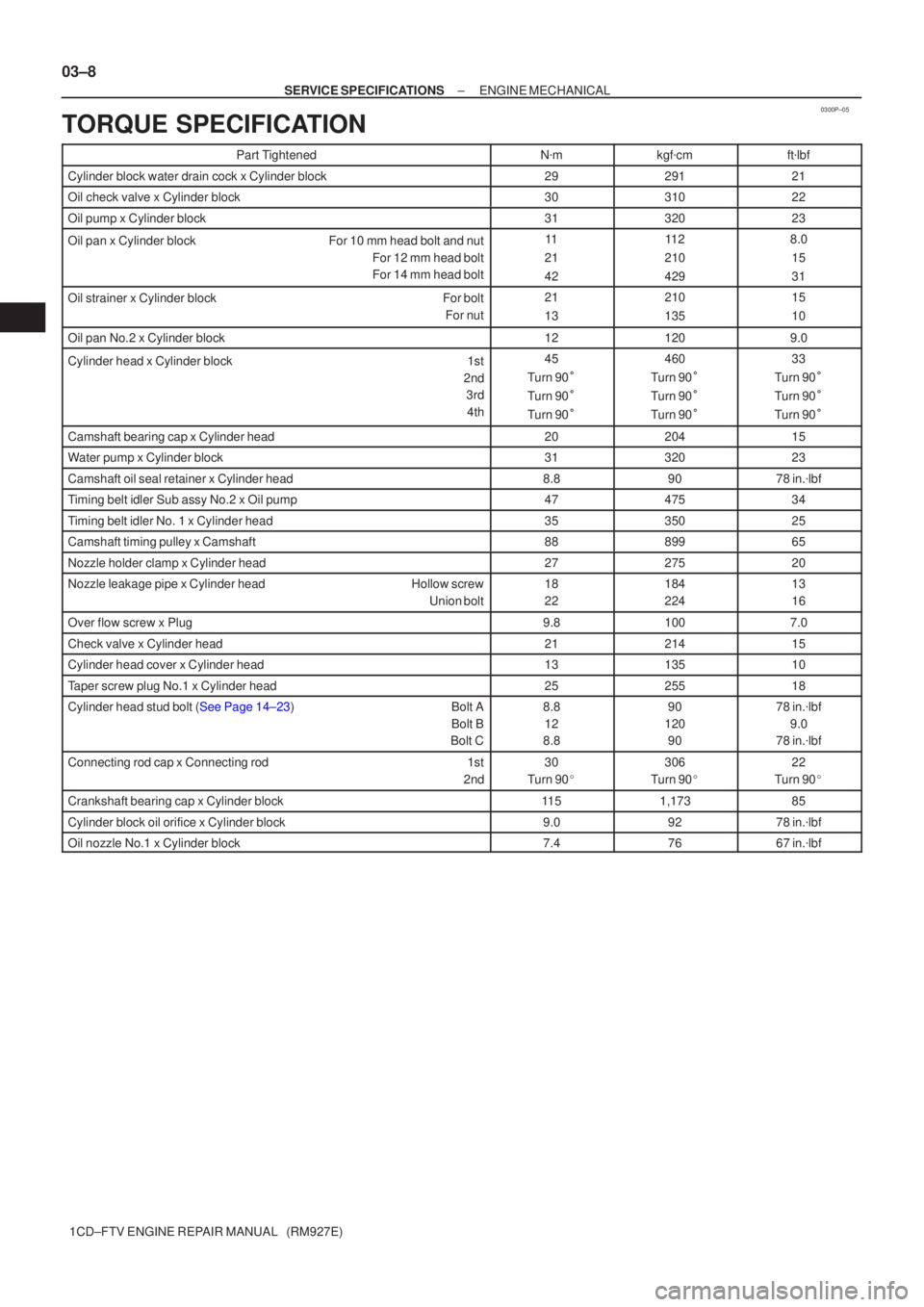
PARTIAL ENGINE ASSY (1CD±FTV)
COMPONENTS
Page 44 of 136
A56694
A62592
SST
A57095
Hexagon
Wrench
(8mm)
SST
A57096
14±4
± ENGINE MECHANICALPARTIAL ENGINE ASSY (1CD±FTV)
1CD±FTV ENGINE REPAIR MANUAL (RM927E)
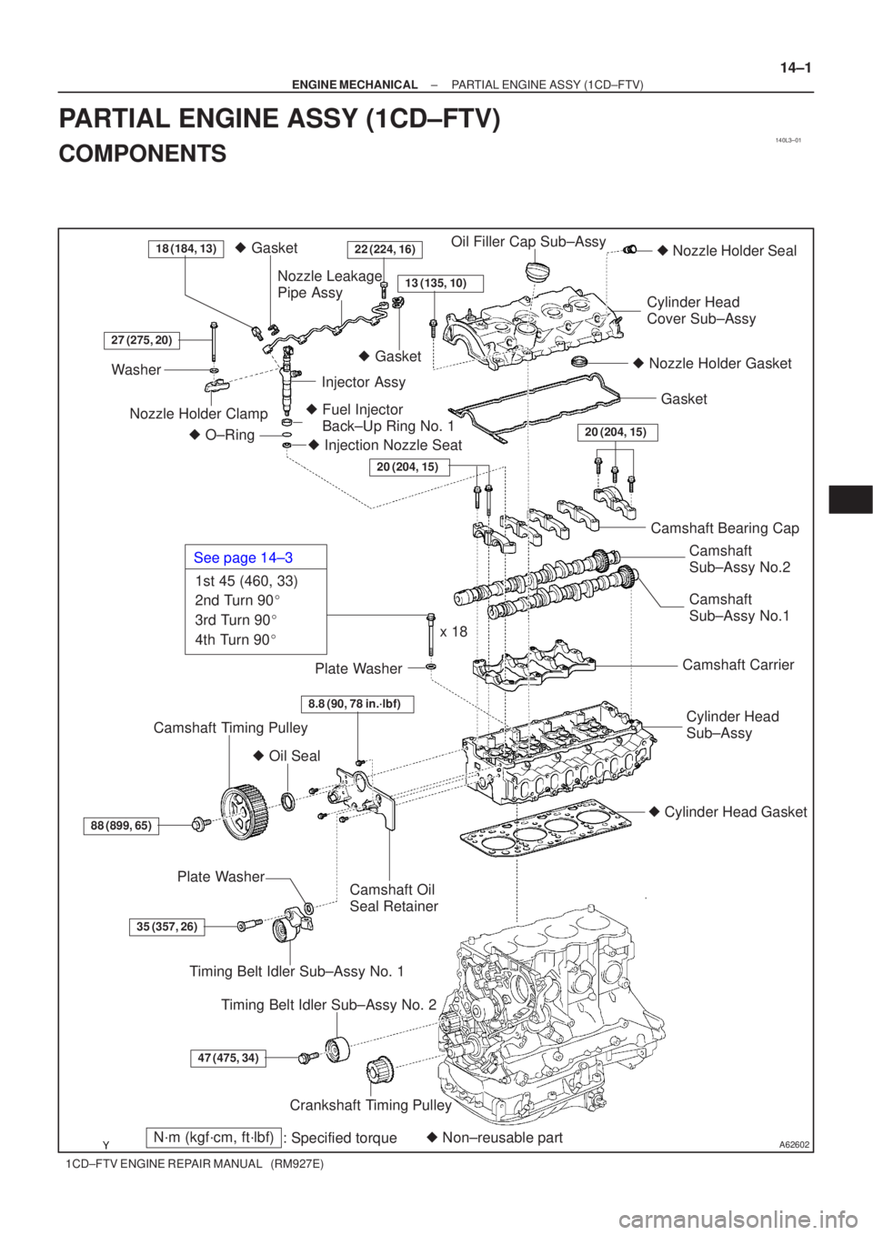
6. REMOVE INJECTOR ASSY
(a) Remove the 4 injectors from the cylinder head.
HINT:
Arrange the injectors in correct order.
7. REMOVE CAMSHAFT TIMING PULLEY
(a) Using SST, remove the pulley bolt.
SST 09960±10010 (09962±01000, 09963±01000)
8. REMOVE TIMING BELT IDLER SUB±ASSY NO.1
(a) Using hexagon wrench (8mm), remove the idler pulley
shaft, idler pulley and plate washer.
9. REMOVE TIMING BELT IDLER SUB±ASSY NO.2
10. REMOVE CRANKSHAFT TIMING PULLEY
(a) If the pulley cannot be removed by hand, use SST to re-
move the timing pulley.
SST 09950±50013 (09951±05010, 09952±05010,
09953±05010, 09953±05020, 09954±05021)
Page 57 of 136
A57098
A09600
Seal Width
2 ± 4 mm
Seal Packing
SST
A57101
Inward
Angle Sensor
A57102
Turn
± ENGINE MECHANICALPARTIAL ENGINE ASSY (1CD±FTV)
14±17
1CD±FTV ENGINE REPAIR MANUAL (RM927E)
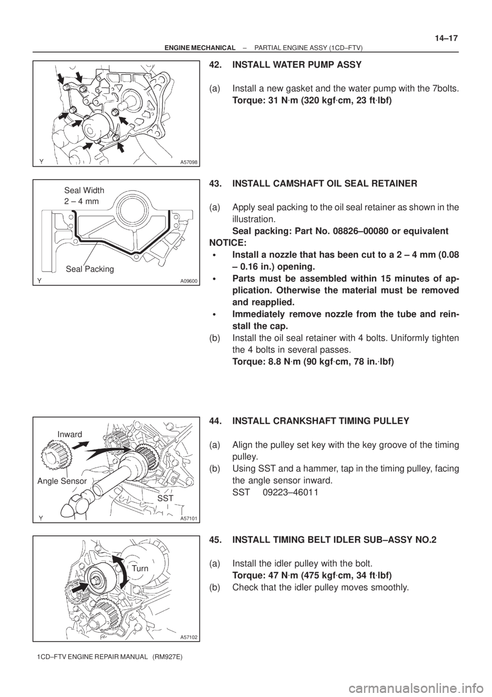
42. INSTALL WATER PUMP ASSY
(a) Install a new gasket and the water pump with the 7bolts.
Torque: 31 N�m (320 kgf�cm, 23 ft�lbf)
43. INSTALL CAMSHAFT OIL SEAL RETAINER
(a) Apply seal packing to the oil seal retainer as shown in the
illustration.
Seal packing: Part No. 08826±00080 or equivalent
NOTICE:
�Install a nozzle that has been cut to a 2 ± 4 mm (0.08
± 0.16 in.) opening.
�Parts must be assembled within 15 minutes of ap-
plication. Otherwise the material must be removed
and reapplied.
�Immediately remove nozzle from the tube and rein-
stall the cap.
(b) Install the oil seal retainer with 4 bolts. Uniformly tighten
the 4 bolts in several passes.
Torque: 8.8 N�m (90 kgf�cm, 78 in.�lbf)
44. INSTALL CRANKSHAFT TIMING PULLEY
(a) Align the pulley set key with the key groove of the timing
pulley.
(b) Using SST and a hammer, tap in the timing pulley, facing
the angle sensor inward.
SST 09223±46011
45. INSTALL TIMING BELT IDLER SUB±ASSY NO.2
(a) Install the idler pulley with the bolt.
Torque: 47 N�m (475 kgf�cm, 34 ft�lbf)
(b) Check that the idler pulley moves smoothly.
Page 58 of 136
A57103
Plate Washer
Hexagon
Wrench
(8mm)
A62592
SST
B08252
B09792
Spring
Convex
14±18
± ENGINE MECHANICALPARTIAL ENGINE ASSY (1CD±FTV)
1CD±FTV ENGINE REPAIR MANUAL (RM927E)
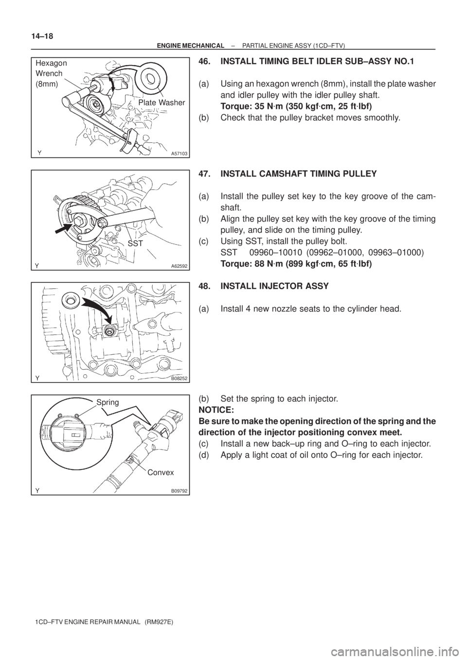
46. INSTALL TIMING BELT IDLER SUB±ASSY NO.1
(a) Using an hexagon wrench (8mm), install the plate washer
and idler pulley with the idler pulley shaft.
Torque: 35 N�m (350 kgf�cm, 25 ft�lbf)
(b) Check that the pulley bracket moves smoothly.
47. INSTALL CAMSHAFT TIMING PULLEY
(a) Install the pulley set key to the key groove of the cam-
shaft.
(b) Align the pulley set key with the key groove of the timing
pulley, and slide on the timing pulley.
(c) Using SST, install the pulley bolt.
SST 09960±10010 (09962±01000, 09963±01000)
Torque: 88 N�m (899 kgf�cm, 65 ft�lbf)
48. INSTALL INJECTOR ASSY
(a) Install 4 new nozzle seats to the cylinder head.
(b) Set the spring to each injector.
NOTICE:
Be sure to make the opening direction of the spring and the
direction of the injector positioning convex meet.
(c) Install a new back±up ring and O±ring to each injector.
(d) Apply a light coat of oil onto O±ring for each injector.