Page 9 of 136
± INTRODUCTIONTERMS
01±9
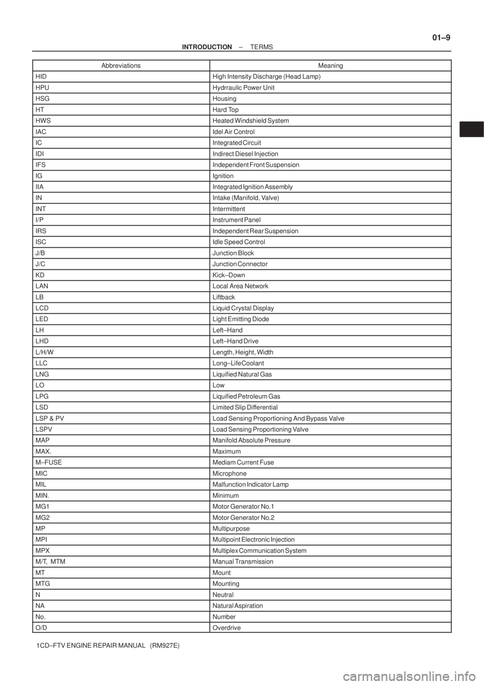
1CD±FTV ENGINE REPAIR MANUAL (RM927E)Abbreviations Meaning
HIDHigh Intensity Discharge (Head Lamp)
HPUHydrraulic Power Unit
HSGHousing
HTHard Top
HWSHeated Windshield System
IACIdel Air Control
ICIntegrated Circuit
IDIIndirect Diesel Injection
IFSIndependent Front Suspension
IGIgnition
IIAIntegrated Ignition Assembly
INIntake (Manifold, Valve)
INTIntermittent
I/PInstrument Panel
IRSIndependent Rear Suspension
ISCIdle Speed Control
J/BJunction Block
J/CJunction Connector
KDKick±Down
LANLocal Area Network
LBLiftback
LCDLiquid Crystal Display
LEDLight Emitting Diode
LHLeft±Hand
LHDLeft±Hand Drive
L/H/WLength, Height, Width
LLCLong±Life Coolant
LNGLiquified Natural Gas
LOLow
LPGLiquified Petroleum Gas
LSDLimited Slip Differential
LSP & PVLoad Sensing Proportioning And Bypass Valve
LSPVLoad Sensing Proportioning Valve
MAPManifold Absolute Pressure
MAX.Maximum
M±FUSEMediam Current Fuse
MICMicrophone
MILMalfunction Indicator Lamp
MIN.Minimum
MG1Motor Generator No.1
MG2Motor Generator No.2
MPMultipurpose
MPIMultipoint Electronic Injection
MPXMultiplex Communication System
M/T, MTMManual Transmission
MTMount
MTGMounting
NNeutral
NANatural Aspiration
No.Number
O/DOverdrive
Page 53 of 136
A
B
C
D
E
A09570
Front
A56055
A09564
1
18 2 3
4 56
78 9 (A)
10 11
12 1314
1516 17(B)
(A) (A) (A) (A)(A) (A)
(A)
(B) (B) (B) (B)
(B) (B) (B) (B) (B)
± ENGINE MECHANICALPARTIAL ENGINE ASSY (1CD±FTV)
14±13
1CD±FTV ENGINE REPAIR MANUAL (RM927E)
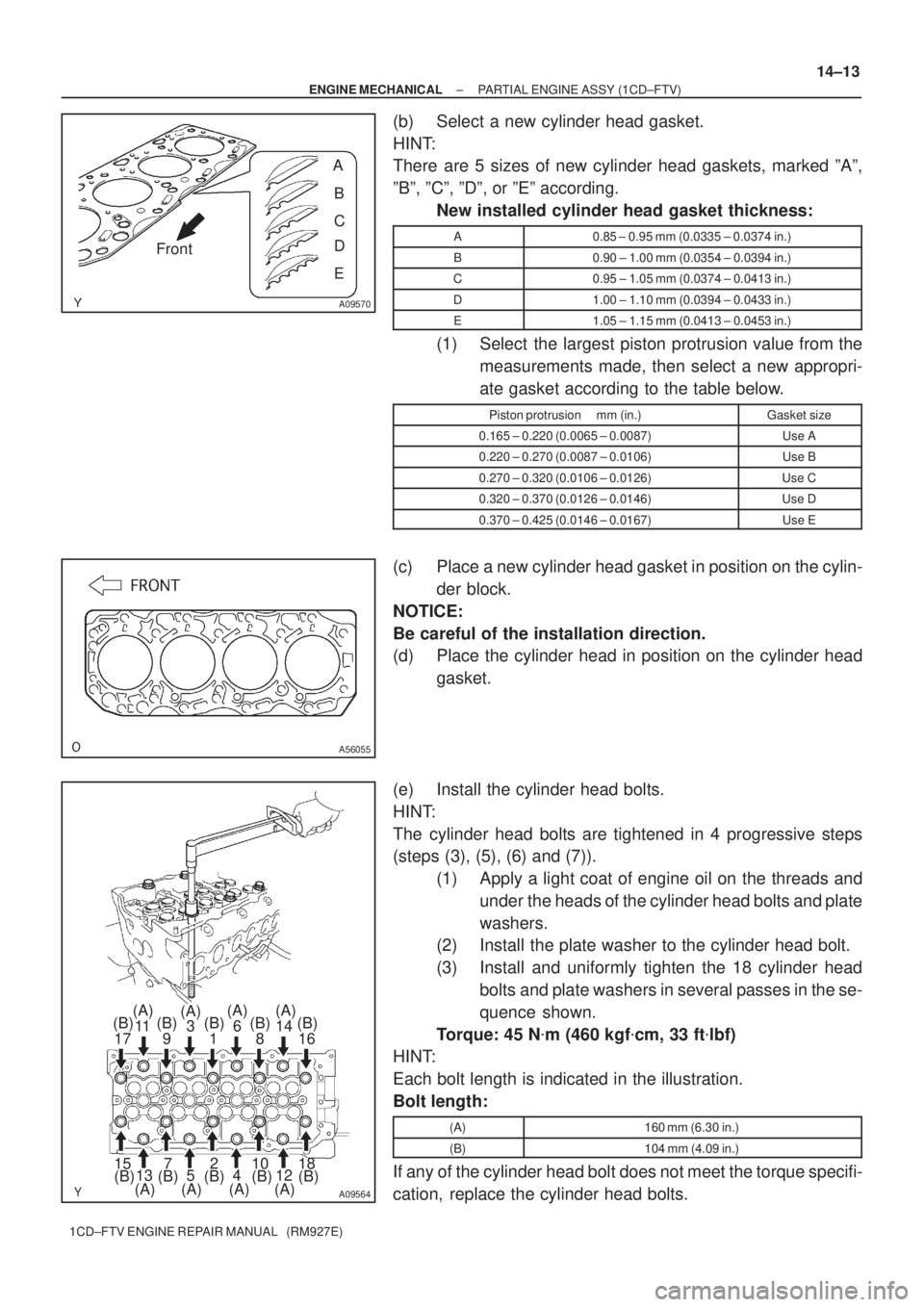
(b) Select a new cylinder head gasket.
HINT:
There are 5 sizes of new cylinder head gaskets, marked ºAº,
ºBº, ºCº, ºDº, or ºEº according.
New installed cylinder head gasket thickness:
A0.85 ± 0.95 mm (0.0335 ± 0.0374 in.)
B0.90 ± 1.00 mm (0.0354 ± 0.0394 in.)
C0.95 ± 1.05 mm (0.0374 ± 0.0413 in.)
D1.00 ± 1.10 mm (0.0394 ± 0.0433 in.)
E1.05 ± 1.15 mm (0.0413 ± 0.0453 in.)
(1) Select the largest piston protrusion value from the
measurements made, then select a new appropri-
ate gasket according to the table below.
Piston protrusion mm (in.)Gasket size
0.165 ± 0.220 (0.0065 ± 0.0087)Use A
0.220 ± 0.270 (0.0087 ± 0.0106)Use B
0.270 ± 0.320 (0.0106 ± 0.0126)Use C
0.320 ± 0.370 (0.0126 ± 0.0146)Use D
0.370 ± 0.425 (0.0146 ± 0.0167)Use E
(c) Place a new cylinder head gasket in position on the cylin-
der block.
NOTICE:
Be careful of the installation direction.
(d) Place the cylinder head in position on the cylinder head
gasket.
(e) Install the cylinder head bolts.
HINT:
The cylinder head bolts are tightened in 4 progressive steps
(steps (3), (5), (6) and (7)).
(1) Apply a light coat of engine oil on the threads and
under the heads of the cylinder head bolts and plate
washers.
(2) Install the plate washer to the cylinder head bolt.
(3) Install and uniformly tighten the 18 cylinder head
bolts and plate washers in several passes in the se-
quence shown.
Torque: 45 N�m (460 kgf�cm, 33 ft�lbf)
HINT:
Each bolt length is indicated in the illustration.
Bolt length:
(A)160 mm (6.30 in.)
(B)104 mm (4.09 in.)
If any of the cylinder head bolt does not meet the torque specifi-
cation, replace the cylinder head bolts.
Page 81 of 136
A09514
Front Mark
(Protrusion)
A09493
90�
90�
A09490
Front
Painted Mark
A09495
± ENGINE MECHANICALCYLINDER BLOCK (1CD±FTV)
14±41
1CD±FTV ENGINE REPAIR MANUAL (RM927E)
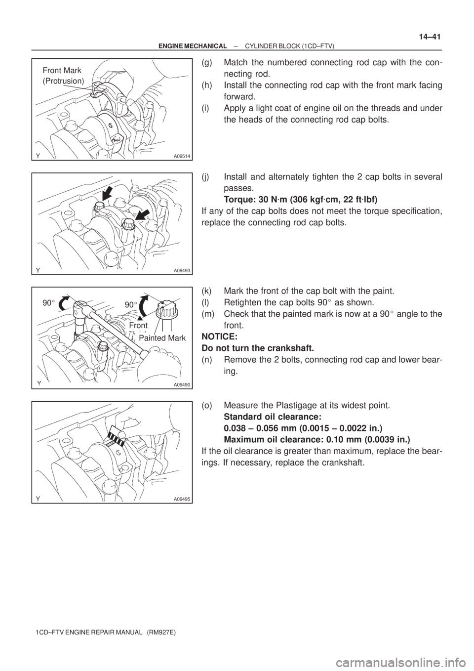
(g) Match the numbered connecting rod cap with the con-
necting rod.
(h) Install the connecting rod cap with the front mark facing
forward.
(i) Apply a light coat of engine oil on the threads and under
the heads of the connecting rod cap bolts.
(j) Install and alternately tighten the 2 cap bolts in several
passes.
Torque: 30 N�m (306 kgf�cm, 22 ft�lbf)
If any of the cap bolts does not meet the torque specification,
replace the connecting rod cap bolts.
(k) Mark the front of the cap bolt with the paint.
(l) Retighten the cap bolts 90� as shown.
(m) Check that the painted mark is now at a 90� angle to the
front.
NOTICE:
Do not turn the crankshaft.
(n) Remove the 2 bolts, connecting rod cap and lower bear-
ing.
(o) Measure the Plastigage at its widest point.
Standard oil clearance:
0.038 ± 0.056 mm (0.0015 ± 0.0022 in.)
Maximum oil clearance: 0.10 mm (0.0039 in.)
If the oil clearance is greater than maximum, replace the bear-
ings. If necessary, replace the crankshaft.
Page 97 of 136
A09512
Groove
A56048
A09497
A56046
A09506
Front Mark
(Arrow)
Front Mark
(Protrusion)
± ENGINE MECHANICALCYLINDER BLOCK (1CD±FTV)
14±57
1CD±FTV ENGINE REPAIR MANUAL (RM927E)
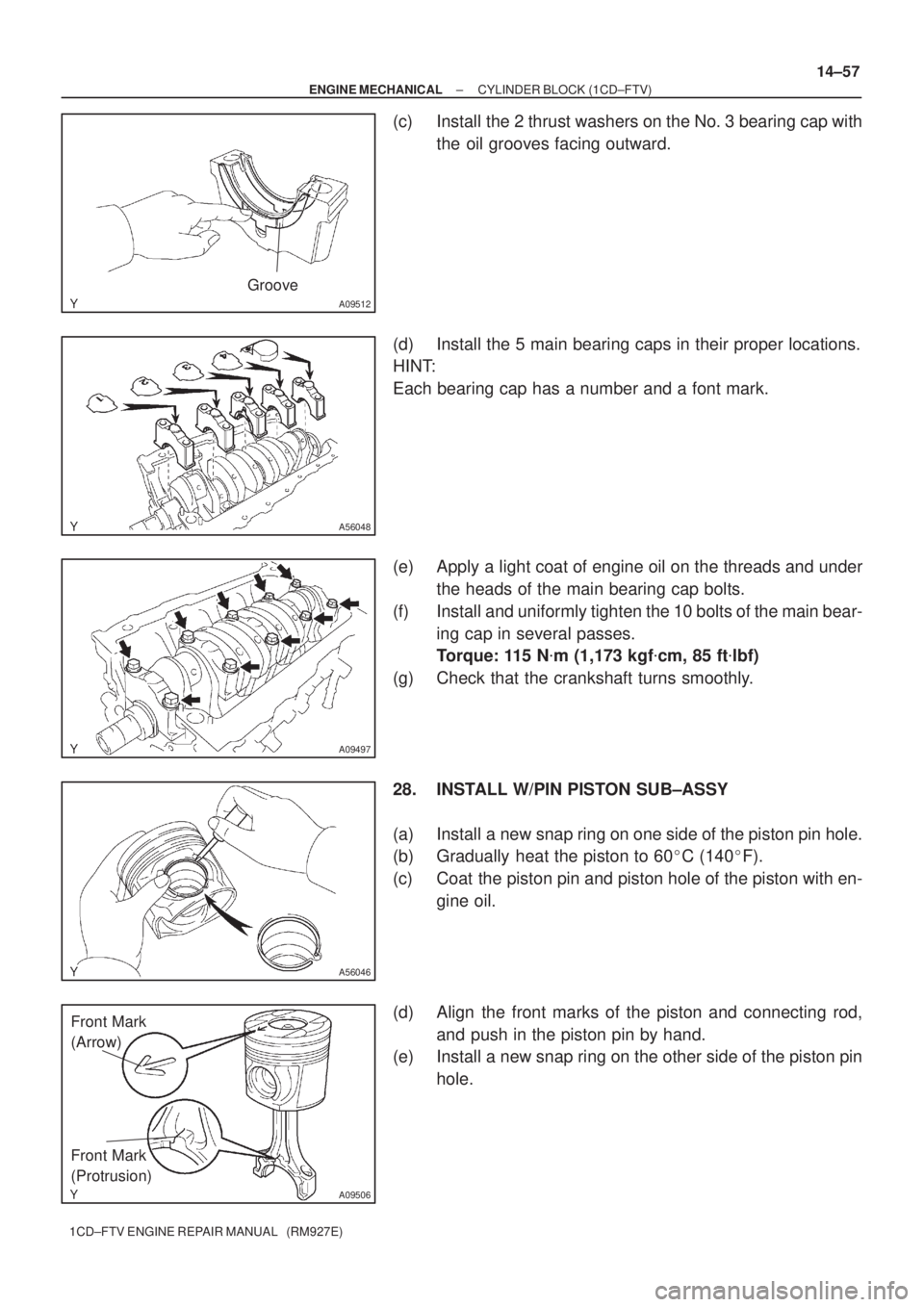
(c) Install the 2 thrust washers on the No. 3 bearing cap with
the oil grooves facing outward.
(d) Install the 5 main bearing caps in their proper locations.
HINT:
Each bearing cap has a number and a font mark.
(e) Apply a light coat of engine oil on the threads and under
the heads of the main bearing cap bolts.
(f) Install and uniformly tighten the 10 bolts of the main bear-
ing cap in several passes.
Torque: 115 N�m (1,173 kgf�cm, 85 ft�lbf)
(g) Check that the crankshaft turns smoothly.
28. INSTALL W/PIN PISTON SUB±ASSY
(a) Install a new snap ring on one side of the piston pin hole.
(b) Gradually heat the piston to 60�C (140�F).
(c) Coat the piston pin and piston hole of the piston with en-
gine oil.
(d) Align the front marks of the piston and connecting rod,
and push in the piston pin by hand.
(e) Install a new snap ring on the other side of the piston pin
hole.
Page 99 of 136
A09511
Front Mark
(Arrow)
Front
Push
A09514
Front Mark
(Protrusion)
A09493
90�
90�
A09490
Painted Mark
Front
± ENGINE MECHANICALCYLINDER BLOCK (1CD±FTV)
14±59
1CD±FTV ENGINE REPAIR MANUAL (RM927E)
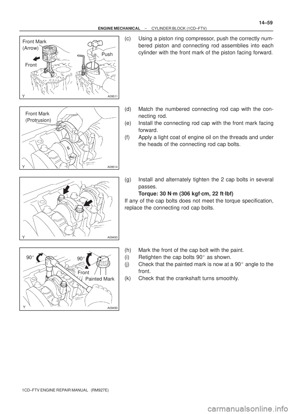
(c) Using a piston ring compressor, push the correctly num-
bered piston and connecting rod assemblies into each
cylinder with the front mark of the piston facing forward.
(d) Match the numbered connecting rod cap with the con-
necting rod.
(e) Install the connecting rod cap with the front mark facing
forward.
(f) Apply a light coat of engine oil on the threads and under
the heads of the connecting rod cap bolts.
(g) Install and alternately tighten the 2 cap bolts in several
passes.
Torque: 30 N�m (306 kgf�cm, 22 ft�lbf)
If any of the cap bolts does not meet the torque specification,
replace the connecting rod cap bolts.
(h) Mark the front of the cap bolt with the paint.
(i) Retighten the cap bolts 90� as shown.
(j) Check that the painted mark is now at a 90� angle to the
front.
(k) Check that the crankshaft turns smoothly.