Page 41 of 136

Camshaft Oil
Seal Retainer
� Nozzle Holder Seal
Nozzle Leakage
Pipe Assy
Nozzle H")
140L3±01
A62602
Cylinder Head
Cover Sub±AssyGasket
Camshaft
Sub±Assy No.2
Camshaft
Sub±Assy No.1
18 (184, 13)
Camshaft Oil
Seal Retainer
� Nozzle Holder Seal
Nozzle Leakage
Pipe Assy
Nozzle Holder Clamp � O±Ring
� Injection Nozzle Seat
� Fuel Injector
Back±Up Ring No. 1
13 (135, 10)
Washer
Camshaft Carrier
Camshaft Bearing Cap
20 (204, 15)
Injector Assy
8.8 (90, 78 in.´lbf)
See page 14±3
1st 45 (460, 33)
2nd Turn 90 �
3rd Turn 90 �
4th Turn 90 �
22 (224, 16)
27 (275, 20)
� Gasket
� Gasket
20 (204, 15)
� Cylinder Head Gasket
� Oil Seal Plate Washer
x 18
Cylinder Head
Sub±Assy
�
Nozzle Holder Gasket
� Non±reusable partN´m (kgf´cm, ft´lbf)
: Specified torque
Oil Filler Cap Sub±Assy
Plate Washer
Camshaft Timing Pulley
88 (899, 65)
35 (357, 26)
Timing Belt Idler Sub±Assy No. 1
Timing Belt Idler Sub±Assy No. 2
47 (475, 34)
Crankshaft Timing Pulley
±
ENGINE MECHANICAL PARTIAL ENGINE ASSY (1CD±FTV)
14±1
1CD±FTV ENGINE REPAIR MANUAL (RM927E)
PARTIAL ENGINE ASSY (1CD±FTV)
COMPONENTS
Page 42 of 136
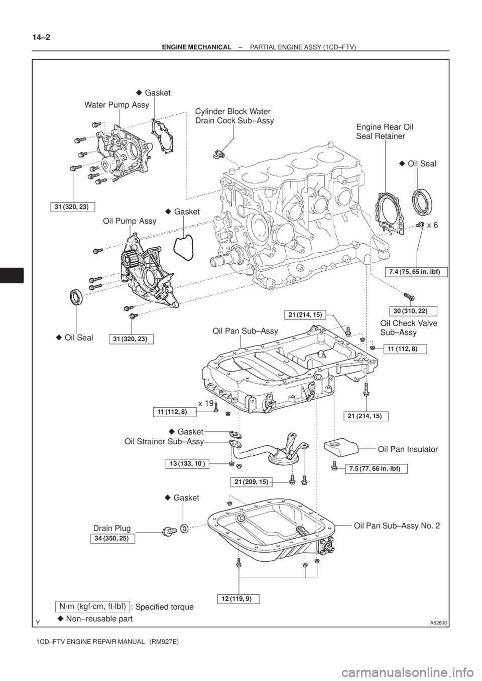
A62603
Engine Rear Oil
Seal Retainer
Oil Check Valve
Sub±Assy
Cylinder Block Water
Drain Cock Sub±Assy
31 (320, 23)
Water Pump Assy
21 (209, 15)
� Gasket � Gasket
x 6
� Gasket
� Oil Seal
Oil Pump Assy
� Oil Seal31 (320, 23)
7.4 (75, 65 in.´lbf)
11 (112, 8)
21 (214, 15)
Oil Pan Sub±Assy
11 (112, 8)x 19
Oil Strainer Sub±Assy
13 (133, 10 )
34 (350, 25)
Drain Plug
� Gasket
7.5 (77, 66 in.´lbf)
Oil Pan Insulator
Oil Pan Sub±Assy No. 2
12 (119, 9)
� Non±reusable part
N´m (kgf´cm, ft´lbf)
: Specified torque
21 (214, 15)30 (310, 22)
14±2
± ENGINE MECHANICALPARTIAL ENGINE ASSY (1CD±FTV)
1CD±FTV ENGINE REPAIR MANUAL (RM927E)
Page 43 of 136
140L4±01
A56691
A62591
A56692
A56693
± ENGINE MECHANICALPARTIAL ENGINE ASSY (1CD±FTV)
14±3
1CD±FTV ENGINE REPAIR MANUAL (RM927E)
OVERHAUL
1. REMOVE OIL FILLER CAP SUB±ASSY
2. REMOVE NOZZLE HOLDER SEAL
(a) Using a screwdriver, pry out the 4 nozzle holder seals.
3. REMOVE CYLINDER HEAD COVER SUB±ASSY
(a) Remove the 10 bolts, cylinder head cover and gasket.
4. REMOVE NOZZLE LEAKAGE PIPE ASSY
(a) Using a hexagon wrench (6mm), remove 4 hollow screws.
(b) Remove the union bolt, nozzle leakage pipe and 5 gas-
kets from the cylinder head and injector.
5. REMOVE NOZZLE HOLDER CLAMP
(a) Remove the 4 bolts, 4 washers and 4 nozzle holder
clamps.
Page 44 of 136
A56694
A62592
SST
A57095
Hexagon
Wrench
(8mm)
SST
A57096
14±4
± ENGINE MECHANICALPARTIAL ENGINE ASSY (1CD±FTV)
1CD±FTV ENGINE REPAIR MANUAL (RM927E)
6. REMOVE INJECTOR ASSY
(a) Remove the 4 injectors from the cylinder head.
HINT:
Arrange the injectors in correct order.
7. REMOVE CAMSHAFT TIMING PULLEY
(a) Using SST, remove the pulley bolt.
SST 09960±10010 (09962±01000, 09963±01000)
8. REMOVE TIMING BELT IDLER SUB±ASSY NO.1
(a) Using hexagon wrench (8mm), remove the idler pulley
shaft, idler pulley and plate washer.
9. REMOVE TIMING BELT IDLER SUB±ASSY NO.2
10. REMOVE CRANKSHAFT TIMING PULLEY
(a) If the pulley cannot be removed by hand, use SST to re-
move the timing pulley.
SST 09950±50013 (09951±05010, 09952±05010,
09953±05010, 09953±05020, 09954±05021)
Page 45 of 136
A57097
A57098
A09650
1 3
24
576
8
9
10 11
12
13 14
15
A09624
± ENGINE MECHANICALPARTIAL ENGINE ASSY (1CD±FTV)
14±5
1CD±FTV ENGINE REPAIR MANUAL (RM927E)
11. REMOVE CAMSHAFT OIL SEAL RETAINER
(a) Remove the 4 bolts.
(b) Using a screwdriver, remove the oil seal retainer by prying
the portions between the oil seal retainer and camshaft
bearing cap.
12. REMOVE WATER PUMP ASSY
(a) Remove the 7 bolts, water pump and gasket.
13. REMOVE CAMSHAFT SUB±ASSY, NO.2
(a) Uniformly loosen and remove the 15 bearing cap bolts in
several passes in the sequence shown.
(b) Remove the 5 bearing caps.
(c) Remove the camshaft No. 2.
14. REMOVE CAMSHAFT SUB±ASSY, NO.1
(a) Remove the camshaft from the cylinder head.
(b) Remove the camshaft carrier from the cylinder head.
Page 46 of 136

1CD±FTV ENGINE REPAIR MANUAL (RM927E)
15. REMOVE CYLI")
A09566
2
1 3
45
67 8
9
14 15 16
17 1211 1013
18
A09563
Pry
A56695
SSTSST
B08601
A56696
14±6
± ENGINE MECHANICALPARTIAL ENGINE ASSY (1CD±FTV)
1CD±FTV ENGINE REPAIR MANUAL (RM927E)
15. REMOVE CYLINDER HEAD SUB±ASSY
(a) Uniformly loosen the 18 cylinder head bolts in several
passes in the sequence shown. Remove the 18 cylinder
head bolts and plate washers.
NOTICE:
Cylinder head warpage or cracking could result from re-
moving bolts in incorrect order.
(b) Lift the cylinder head from the dowels on the cylinder
block, and place the cylinder head on wooden blocks on
a bench.
HINT:
If the cylinder head is lift off, pry between the cylinder head and
cylinder block with a screwdriver.
NOTICE:
Be careful not to damage the contact surfaces of the cylin-
der head and cylinder block.
16. REMOVE OIL PAN SUB±ASSY NO.2
(a) Remove the 16 bolts and 3 nuts.
(b) Insert the blade of SST between the No. 1 and No. 2 oil
pans, and cut off the applied seal and remove the No. 2
oil pan.
SST 09032±00100
NOTICE:
Be careful not to damage the contact surfaces of the No. 1
and No. 2 oil pans.
17. REMOVE OIL STRAINER SUB±ASSY
(a) Remove the 2 bolts, 2 nuts, oil strainer and gasket.
Page 47 of 136
A56697
A56698
A56699
A09518
A09519
Hexagon
Wrench
(8mm)
± ENGINE MECHANICALPARTIAL ENGINE ASSY (1CD±FTV)
14±7
1CD±FTV ENGINE REPAIR MANUAL (RM927E)
18. REMOVE OIL PAN SUB±ASSY
(a) Remove the 19 bolts and 3 nuts.
(b) Using a screwdriver, remove the oil pan by prying the por-
tions between the cylinder block and No. 1 oil pan.
NOTICE:
Be careful not to damage the contact surfaces of the cylin-
der block and No. 1 oil pan.
19. REMOVE OIL PUMP ASSY
(a) Remove the 9 bolts.
(b) Remove the oil pump by prying a screwdriver between the
oil pump and main bearing cap.
(c) Remove the gasket.
20. REMOVE ENGINE REAR OIL SEAL RETAINER
(a) Remove the 6 bolts.
(b) Using a screwdriver, remove the oil seal retainer by prying
the portions between the oil seal retainer and main bear-
ing cap.
21. REMOVE OIL CHECK VALVE SUB±ASSY
(a) Using hexagon wrench (8mm), remove the pressure
valve and gasket.
Page 48 of 136
A09619
SST
A09620
B07976
A56700
SST
14±8
± ENGINE MECHANICALPARTIAL ENGINE ASSY (1CD±FTV)
1CD±FTV ENGINE REPAIR MANUAL (RM927E)
22. REMOVE CYLINDER BLOCK WATER DRAIN COCK SUB±ASSY
23. REMOVE CAMSHAFT OIL SEAL
(a) Using a screwdriver and a hammer, tap out the oil seal.
24. INSTALL CAMSHAFT OIL SEAL
(a) Using SST and a hammer, tap in a new oil seal until its sur-
face is flush with the camshaft oil seal retainer edge.
SST 09223±46011
25. REMOVE CRANKSHAFT SEAL
(a) Using a screwdriver and a hammer, tap out the oil seal.
26. INSTALL CRANKSHAFT SEAL
(a) Using SST and a hammer, tap in a new oil seal until its sur-
face is flush with the oil pump edge.
SST 09316±60011 (09316±00011, 09316±00021)

14±3
1CD±FTV ENGINE REPAIR MANUAL (RM927E)
OVERHAUL
1. REMOVE OIL FILLER CAP SUB±ASSY
2. REMOVE NOZZLE HOL")

SST
A57096
14±4
± ENGINE MECHANICALPARTIAL ENGINE ASSY (1CD±FTV)
1CD±FTV ENGINE REPAIR MANUAL (RM927E)
6. REMOVE INJECTOR ASSY
(a) Remove the 4 in")

14±5
1CD±FTV ENGINE REPAIR MANUAL (RM927E)
11. REMOVE CAMSHAFT OIL SEAL RETAINER
(a)")

± ENGINE MECHANICALPARTIAL ENGINE ASSY (1CD±FTV)
14±7
1CD±FTV ENGINE REPAIR MANUAL (RM927E)
18. REMOVE OIL PAN SUB±ASSY
(a) Remove the 1")

1CD±FTV ENGINE REPAIR MANUAL (RM927E)
22. REMOVE CYLINDER BLOCK WATER DRAIN COCK SUB±ASSY
23. REMOVE CA")