Page 33 of 136
13034±01
A62601
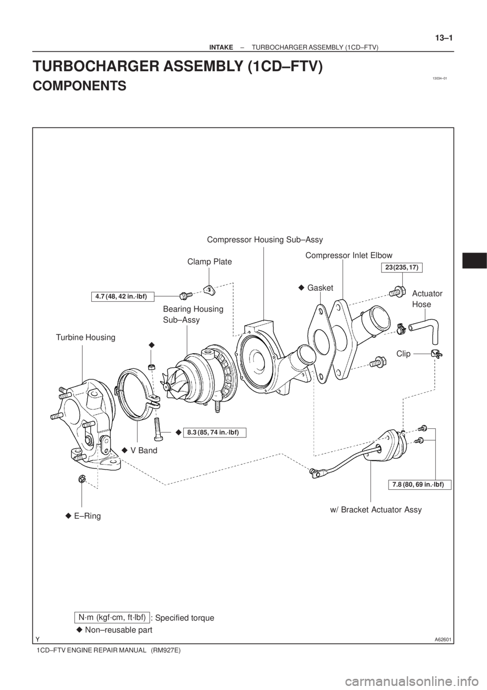
Turbine HousingBearing Housing
Sub±AssyClamp PlateCompressor Housing Sub±Assy
Compressor Inlet Elbow
Actuator
Hose
Clip
w/ Bracket Actuator Assy � V Band� Gasket
� E±Ring
4.7 (48, 42 in.´lbf)
�
7.8 (80, 69 in.´lbf)
�
23 (235, 17)
� Non±reusable part
N´m (kgf´cm, ft´lbf)
: Specified torque
8.3 (85, 74 in.´lbf)
± INTAKETURBOCHARGER ASSEMBLY (1CD±FTV)
13±1
1CD±FTV ENGINE REPAIR MANUAL (RM927E)
TURBOCHARGER ASSEMBLY (1CD±FTV)
COMPONENTS
Page 34 of 136

1CD±FTV ENGINE REPAIR MANUAL (RM927E)
OVERHAUL
1. REMOVE COMPRESSOR INLET ELBOW")
13035±01
B08025
Turn
A62443
Move
SST
B08048
Move
A62444
Open
SST
2mm 13±2
± INTAKETURBOCHARGER ASSEMBLY (1CD±FTV)
1CD±FTV ENGINE REPAIR MANUAL (RM927E)
OVERHAUL
1. REMOVE COMPRESSOR INLET ELBOW
(a) Remove 2 bolts and the compressor inlet elbow.
2. INSPECT TURBOCHARGER SUB±ASSY
(a) Inspect turbine shaft rotation
(1) Grasp the edge of the turbine shaft, and turn it.
(2) Check that the turbine shaft turns smoothly.
If the turbine shaft turns remarkably heavily or stuck, replace
the bearing housing. At that time, check also the interference
with the turbine housing and compressor housing.
(b) Inspect axial play of turbine shaft
(1) Using a dial indicator, insert the needle of the dial in-
dicator into the exhaust side.
(2) Move the turbine shaft in an axial direction, mea-
sure the axial play of the turbine shaft.
Maximum oil clearance: 0.09 mm (0.0035 in.) or less
If the axial play is greater than maximum, replace the bearing
housing. At that time, check also the interference with the tur-
bine housing and compressor housing.
(c) Inspect radial play of turbine shaft
(1) Using SST and a dial indicator, insert the needle of
the dial indicator into the oil outlet hole, and set it in
the center of the turbine shaft.
SST 09992±00600
(2) Move the turbine shaft in a radial direction, measure
the radial play of the turbine shaft.
Maximum oil clearance: 0.16 mm (0.0063 in.) or less
If the radial play is greater than maximum, replace the bearing
housing. At that time, check also the interference with the tur-
bine housing and compressor housing.
(d) Inspect actuator and waste gate valve operation.
(1) Disconnect the actuator hose from the compressor
housing.
(2) Using SST and a dial indicator, read the graduation
of SST when the actuator push rod moved 2 mm
(0.079 in.).
SST 09992±00242
Standard pressure:
129 ± 140 kPa (1.32 ± 1.43 kgf/cm
2, 18.7 ± 20.3 psi)
Page 35 of 136

13±3
1CD±FTV ENGINE REPAIR MANUAL (RM927E)
(e) Move the actuator push rod, and check")
A62445
Torx Socket Wrench
A62446
Matchmarks
A62447
A62448
Matchmarks
± INTAKETURBOCHARGER ASSEMBLY (1CD±FTV)
13±3
1CD±FTV ENGINE REPAIR MANUAL (RM927E)
(e) Move the actuator push rod, and check that the waste
gate valve is open.
If operation is not as specified, replace the actuator and/or tur-
bine housing.
NOTICE:
Never apply more than 161 kPa (1.64 kgf/cm
2, 28.5 psi) of
pressure on the actuator.
(f) Reconnect the actuator hose to the compressor housing.
3. REMOVE W/BRACKET ACTUATOR ASSY
(a) Remove the actuator hose.
(b) Using a torx socket wrench (T30), remove the 2 screws
holding the actuator to the compressor housing.
(c) Remove the E±ring holding the actuator push rod to the
waste gate valve link, and remove the actuator w/ brack-
et.
4. REMOVE COMPRESSOR HOUSING SUB±ASSY
(a) Place the matchmarks on the compressor housing and
the bearing housing.
(b) Remove the 5 bolts and 5 clamp plates.
(c) Using a plastic±faced hammer, tap out the compressor
housing.
NOTICE:
Remove the compressor housing as straight as possible
and do not make the impeller wheel interfere with the com-
pressor housing.
5. REMOVE BEARING HOUSING SUB±ASSY
(a) Place the matchmarks on the V band, turbine housing
and bearing housing.
(b) Remove the flat head square neck bolt, nut and V band.
Page 36 of 136

1CD±FTV ENGINE REPAIR MANUAL (RM927E)
(c) Using a plastic±fac")
B08059
B08067
B08068
Seal Surface
Shroud Section
B08065
Inside Diameter Section
B08066
13±4
± INTAKETURBOCHARGER ASSEMBLY (1CD±FTV)
1CD±FTV ENGINE REPAIR MANUAL (RM927E)
(c) Using a plastic±faced hammer, tap out the bearing hous-
ing.
NOTICE:
Remove the bearing housing as straight as possible and do
not make the turbine wheel interfere with the turbine hous-
ing.
6. CLEAN TURBINE HOUSING
(a) Spray the engine conditioner to the section where the car-
bon dirt is adhered.
NOTICE:
Be careful not to erase the matchmark of the turbine hous-
ing.
(b) Using a wire brush, remove all the carbon dirt inside the
turbine housing.
NOTICE:
Clean the seal surface and shroud section shown in the il-
lustration sufficiently. And clean the waste gate valve seat
sufficiently, too.
HINT:
When the carbon dirt is heavily adhered, remove it using the
screwdriver and the like.
(c) Clean the inside diameter section with a sandpaper (No.
100) until the metal surface can be seen.
NOTICE:
If the cleaning is not enough, installation of the bearing
housing becomes harder, so clean it sufficiently.
(d) Wash with compressed air or a steam cleaner.
NOTICE:
Wash sufficiently without leaving any irregular objects.
Page 37 of 136

13±5
1CD±FTV ENGINE REPAIR MANUAL (RM927E)
(e) Check that there is no severe damage on the seal su")
B08064
Seal Surface
Shroud Section
B08069
A62449
A62450
± INTAKETURBOCHARGER ASSEMBLY (1CD±FTV)
13±5
1CD±FTV ENGINE REPAIR MANUAL (RM927E)
(e) Check that there is no severe damage on the seal surface
with the bearing housing.
(f) Check that there is no bore made by the interference with
the turbine wheel in the shroud section.
If the turbine housing is having remarkable damage or bore, re-
place the turbine housing and bearing housing.
(g) Move the waste gate valve link and check that it runs
smoothly without sticking.
If the link is bad running, clean again. If it is bad running, even
after cleaning, replace the turbine housing.
7. CLEAN COMPRESSOR HOUSING SUB±ASSY
(a) Remove any old packing (FIPG) material and be careful
not to drop any oil on the contact surfaces of the compres-
sor housing and bearing housing.
(1) Using a razor blade and gasket scraper, remove all
the old packing (FIPG) material from the gasket sur-
faces.
(2) Thoroughly clean all components to remove all the
loose material.
(3) Using a non±residue solvent, clean both sealing
surfaces.
(b) Wipe off the dirt from the inside of the housing with a shop
rag.
(c) Check that there is no severe interference with the impel-
ler wheel.
If it is having bur made by a slight interference damage, remove
it with a sandpaper (No. 400) and blow with compressed air.
8. INSTALL BEARING HOUSING SUB±ASSY
(a) Align the pin of the turbine housing with the pin hole of the
bearing housing.
Page 38 of 136

1CD±FTV ENGINE REPAIR MANUAL (RM927E)
(b) Install the bearing housing to the turbine housing.
NO")
A62451
A62452
A62960
Old V Band
New V Band
Matchmark
13±6
± INTAKETURBOCHARGER ASSEMBLY (1CD±FTV)
1CD±FTV ENGINE REPAIR MANUAL (RM927E)
(b) Install the bearing housing to the turbine housing.
NOTICE:
�Install the bearing housing straight, and be careful
not to damage the turbine wheel.
�In case of having difficulty of pressing in the bearing
housing to install with a hand due to hard engage-
ment, apply the procedure (c).
HINT:
Apply a little penetrate rust prevention lubricant onto the en-
gagement section to make installation easier.
(c) In case that the engagement of the bearing housing is
hard, using SST and a press, install the bearing housing
while checking the smooth rotation of the impeller wheel.
SST 09350±32014 (09351±32070)
NOTICE:
�Do not hold the turbine housing with the stud bolts.
�Be sure to install the bearing housing straight without
tilting as the shaft may bent and cause the irregular
noise.
�Press in the bearing housing slowly. When the rota-
tion of the impeller wheel becomes heavy, return the
press immediately and do the operation again.
�After installation, check that the turbine shaft turns
smoothly.
(d) Place a new and old (used) V bands in line, then reprint
the matchmark position on the old V band to the new one.
Page 39 of 136

13±7
1CD±FTV ENGINE REPAIR MANUAL (RM927E)
(e)")
A62448
Matchmarks
B08239
Approx. 38�
A62453
60�3 4 5
2
1 60�
A62454
Seal Width
0.1 ± 0.2 mmSeal
Packing
± INTAKETURBOCHARGER ASSEMBLY (1CD±FTV)
13±7
1CD±FTV ENGINE REPAIR MANUAL (RM927E)
(e) Align the matchmarks on the new V band, turbine housing
and bearing housing, and temporarily torque with a new
bolt and nut.
Torque: 8.3 N�m (85 kgf�cm, 74 in.�lbf)
HINT:
When the marks are erased, make the matching openings meet
at the position shown in the illustration.
(f) Using a brass bar and hammer, hit 2 or 3 times lightly at
each place in order of 1 through 5.
(g) Torque the bolt and nut more.
Torque: 8.3 N�m (85 kgf�cm, 74 in.�lbf)
(h) Using a brass bar and hammer, hit 2 or 3 times lightly at
each place of 1 and 4.
(i) Torque the bolt and nut completely.
Torque: 8.3 N�m (85 kgf�cm, 74 in.�lbf)
9. INSTALL COMPRESSOR HOUSING SUB±ASSY
(a) In case of reusing the compressor housing and bearing
housing:
(1) Apply seal packing to the compressor housing as
shown in the illustration.
Seal packing: Part No. 08826±00080 or equivalent
NOTICE:
Avoid applying an excessive amount to the surface.
�Install a nozzle that has been cut to a 0.1 ± 0.2
mm (0.004 ± 0.008 in.) opening.
�Parts must be assembled within 7 minutes of
application. Otherwise the material must be
removed and reapplied.
�Immediately remove nozzle from the tube
and reinstall the cap.
Page 40 of 136

1CD±FTV ENGINE REPAIR MANUAL (RM927E)
(2) Align the matchmarks on the compressor h")
A62455
Matchmarks
A62456
Cut
Protractor
Steel Square49�
A62457
SST
13±8
± INTAKETURBOCHARGER ASSEMBLY (1CD±FTV)
1CD±FTV ENGINE REPAIR MANUAL (RM927E)
(2) Align the matchmarks on the compressor housing
and bearing housing, and install them.
NOTICE:
�Do not make the impeller wheel interfere with the
compressor housing.
�Check that the turbine shaft turns smoothly.
(3) Using a steel square and protractor, check the
installation angle of the outlet port of the compres-
sor housing shown in the illustration.
(4) Install the 5 clamp plates and bolts.
Torque: 4.7 N�m (48 kgf�cm, 42 in.�lbf)
(b) In case of using a new compressor housing and/or bear-
ing housing :
(1) Temporally install the compressor housing on the
bearing housing, make the installation angle of the
outlet port of the compressor housing meet at the
position shown in the illustration, and place the
matchmarks.
(2) Remove the compressor housing.
(3) The following procedure is the same as that of reus-
ing the compressor housing and/or bearing hous-
ing.
10. INSTALL W/BRACKET ACTUATOR ASSY
(a) Using a torx wrench (T30), install the actuator w/ bracket
to the compressor housing with the 2 screws.
Torque: 7.8 N�m (80 kgf�cm, 69 in.�lbf)
(b) Using SST, move the actuator push rod.
SST 09992±00242
NOTICE:
Never apply more than 197 kPa (2.01 kgf/cm
2, 28.5 psi) of
pressure on the actuator.
(c) Connect the actuator push rod to the waste gate valve link
with a new E±ring.
NOTICE:
Do not use a hammer, etc. to force the actuator push rod
onto the waste gate valve link.
(d) Remove the SST.
(e) Connect the actuator hose.
11. INSTALL COMPRESSOR INLET ELBOW
Torque: 23 N�m (235 kgf�cm, 17 ft�lbf)