Page 129 of 136

Length
P13535
17 mm
Socket
Wrench
A51920
Cord ClipA
B
A A
A64533
Inside
A51921
19±28
± STARTING & CHARGINGGENERATOR ASSY(90A) (1CD±FTV)
1CD±FTV ENGINE REPAIR MANUAL (RM927E)
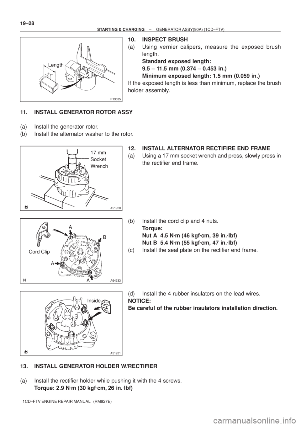
10. INSPECT BRUSH
(a) Using vernier calipers, measure the exposed brush
length.
Standard exposed length:
9.5 ± 11.5 mm (0.374 ± 0.453 in.)
Minimum exposed length: 1.5 mm (0.059 in.)
If the exposed length is less than minimum, replace the brush
holder assembly.
11. INSTALL GENERATOR ROTOR ASSY
(a) Install the generator rotor.
(b) Install the alternator washer to the rotor.
12. INSTALL ALTERNATOR RECTIFIRE END FRAME
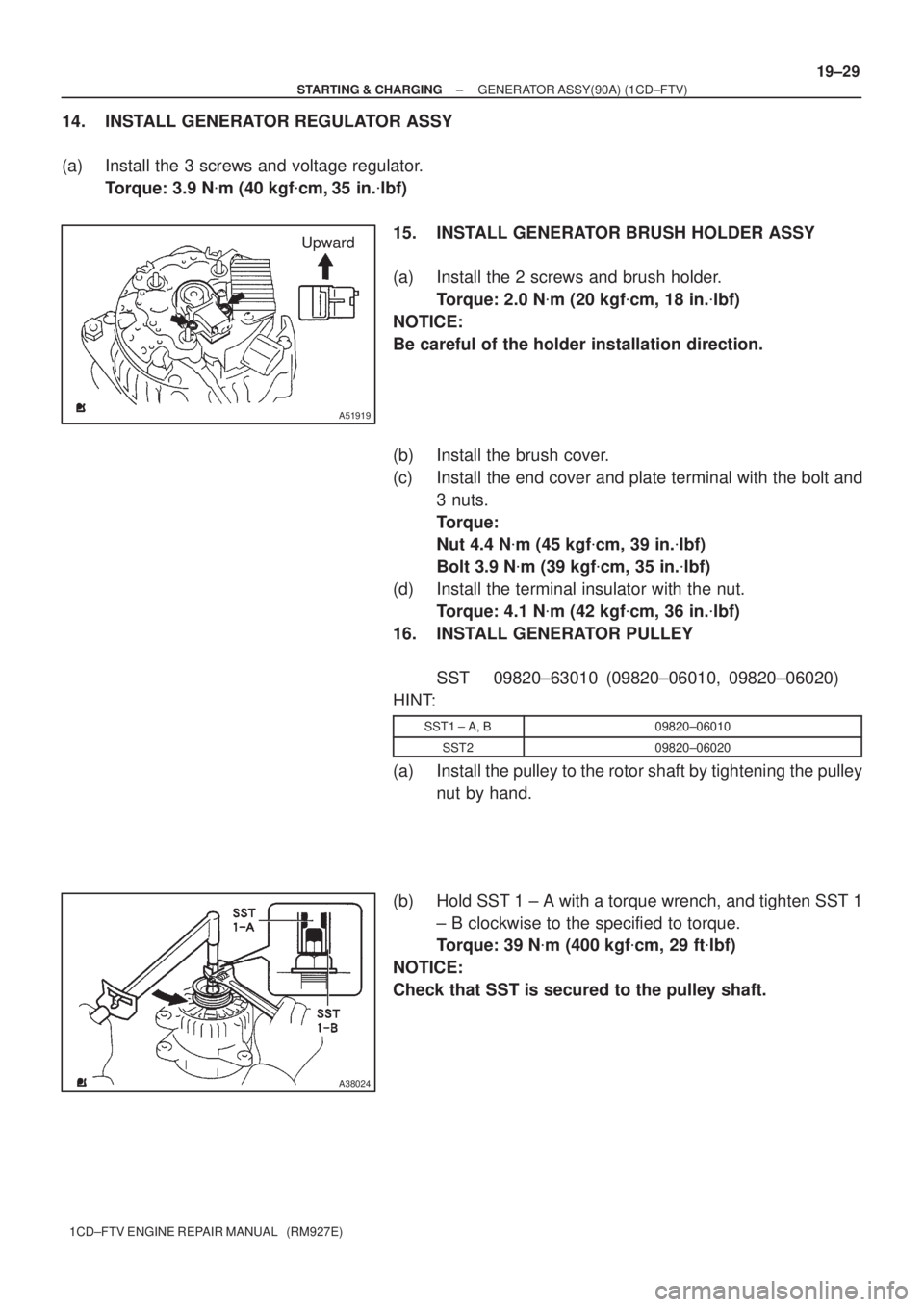
(a) Using a 17 mm socket wrench and press, slowly press in
the rectifier end frame.
(b) Install the cord clip and 4 nuts.
Torque:
Nut A 4.5 N�m (46 kgf�cm, 39 in.�lbf)
Nut B 5.4 N�m (55 kgf�cm, 47 in.�lbf)
(c) Install the seal plate on the rectifier end frame.
(d) Install the 4 rubber insulators on the lead wires.
NOTICE:
Be careful of the rubber insulators installation direction.
13. INSTALL GENERATOR HOLDER W/RECTIFIER
(a) Install the rectifier holder while pushing it with the 4 screws.
Torque: 2.9 N�m (30 kgf�cm, 26 in.�lbf)
Page 130 of 136

Upward
A51919
A38024
± STARTING & CHARGINGGENERATOR ASSY(90A) (1CD±FTV)
19±29
1CD±FTV ENGINE REPAIR MANUAL (RM927E)
14. INSTALL GENERATOR REGULATOR ASSY
(a) Install the 3 screws and voltage regulator.
Torque: 3.9 N�m (40 kgf�cm, 35 in.�lbf)
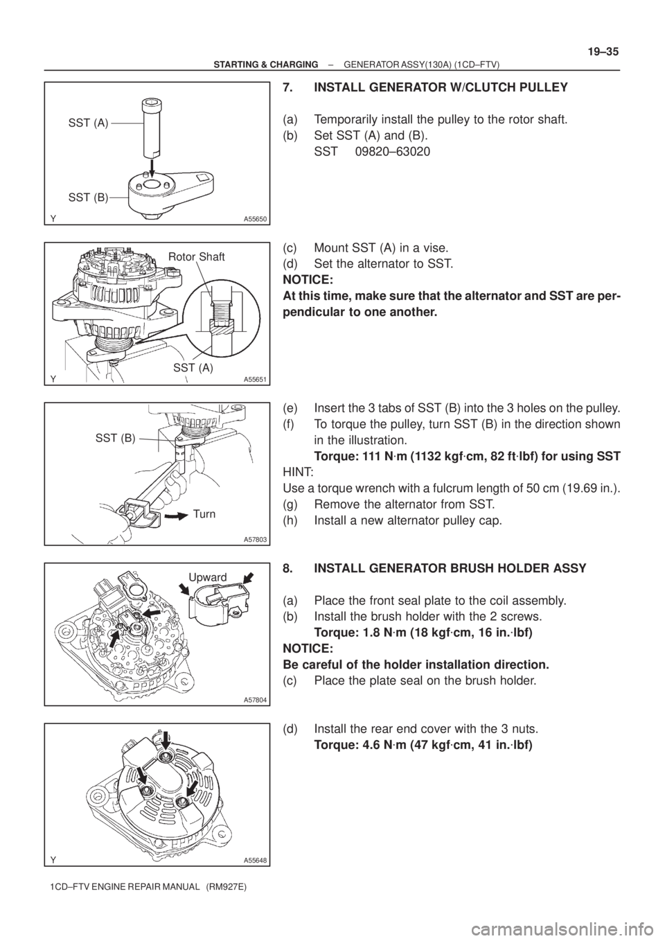
15. INSTALL GENERATOR BRUSH HOLDER ASSY
(a) Install the 2 screws and brush holder.
Torque: 2.0 N�m (20 kgf�cm, 18 in.�lbf)
NOTICE:
Be careful of the holder installation direction.
(b) Install the brush cover.
(c) Install the end cover and plate terminal with the bolt and
3 nuts.
Torque:
Nut 4.4 N�m (45 kgf�cm, 39 in.�lbf)
Bolt 3.9 N�m (39 kgf�cm, 35 in.�lbf)
(d) Install the terminal insulator with the nut.
Torque: 4.1 N�m (42 kgf�cm, 36 in.�lbf)
16. INSTALL GENERATOR PULLEY
SST 09820±63010 (09820±06010, 09820±06020)
HINT:
SST1 ± A, B09820±06010
SST209820±06020
(a) Install the pulley to the rotor shaft by tightening the pulley
nut by hand.
(b) Hold SST 1 ± A with a torque wrench, and tighten SST 1
± B clockwise to the specified to torque.
Torque: 39 N�m (400 kgf�cm, 29 ft�lbf)
NOTICE:
Check that SST is secured to the pulley shaft.
Page 131 of 136
A38025
SST 1 ± A
A38126
A38105
19±30
± STARTING & CHARGINGGENERATOR ASSY(90A) (1CD±FTV)
1CD±FTV ENGINE REPAIR MANUAL (RM927E)
(c) Mount SST 2 in a vise.
(d) Insert SST 1 ± A, B into SST 2, and attach the pulley nut
to SST 2.
(e) Tighten the pulley nut, turn SST 1 ± A in the direction
shown in the illustration.
Torque: 111 N�m (1,125 kgf�cm, 81 ft�lbf)
(f) Remove the alternator form SST 2.
(g) Turn SST 1 ± B, and remove SST 1 ± A, B.
(h) Turn the pulley, and check that the pulley moves smooth-
ly.
Page 132 of 136
190AI±01
A62720
Drive End Frame Assy Generator w/ Clutch Pulley
Alternator Pulley CapGenerator Rotor Assy
Rear End Cover
Sub±Assy Rear Seal Plate
Generator Brush
Holder Assy
Front Seal
Plate
Alternator Coil Assy
N´m (kgf´cm, ft´lbf)
: Specified torque
5.8 (59, 51 in.´lbf)
1.8 (18, 16 in.´lbf)
4.6 (47, 41 in.´lbf)
± STARTING & CHARGINGGENERATOR ASSY(130A) (1CD±FTV)
19±31
1CD±FTV ENGINE REPAIR MANUAL (RM927E)
GENERATOR ASSY(130A) (1CD±FTV)
COMPONENTS
Page 133 of 136
190AJ±01
A55648
A55649
A55650
SST (A)
SST (B)
A55651
Rotor Shaft
SST (A)
19±32
± STARTING & CHARGINGGENERATOR ASSY(130A) (1CD±FTV)
1CD±FTV ENGINE REPAIR MANUAL (RM927E)
OVERHAUL
1. REMOVE GENERATOR BRUSH HOLDER ASSY
(a) Remove the 3 nuts and rear end cover.
(b) Remove the B terminal insulator.
(c) Remove the rear plate seal from the brush holder.
(d) Remove the 2 screws and brush holder.
(e) Remove the front seal plate from the rear frame.
2. REMOVE GENERATOR W/CLUTCH PULLEY
(a) Set SST (A) and (B).
SST 09820±63020
(b) Mount SST (A) in a vise.
(c) Set the alternator to SST.
NOTICE:
At this time, make sure that the alternator and SST are per-
pendicular to one another.
Page 134 of 136
A57794
SST (B)
Turn
A57795
A57796
SST
A57797
A57798
± STARTING & CHARGINGGENERATOR ASSY(130A) (1CD±FTV)
19±33
1CD±FTV ENGINE REPAIR MANUAL (RM927E)
(d) Insert the 3 tabs of SST (B) into the 3 holes on the pulley.
(e) To loosen the pulley, turn SST (B) in the direction shown
in the illustration.
(f) Remove the alternator from SST.
(g) Remove the pulley from the rotor shaft.
3. REMOVE GENERATOR ROTOR ASSY
(a) Remove the 4 through bolts.
(b) Using SST, remove the coil assembly.
SST 09950±40011 (09951±04020, 09952±04010,
09953±04020, 09954±04010, 09955±04071,
09958±04011)
(c) Remove the alternator washer.
(d) Remove the rotor from the drive end frame.
4. INSPECT GENERATOR ROTOR ASSY
(a) Using an ohmmeter, check that there is continuity be-
tween the slip rings.
Standard resistance: 2.3 ± 2.7 � at 20�C (68�F)
(b) Using an ohmmeter, check that there is no continuity be-
tween the slip ring and rotor.
Page 135 of 136
A57799
A57800
A57801
A57802
Socket
Wrench
(29 mm)
A57795
19±34
± STARTING & CHARGINGGENERATOR ASSY(130A) (1CD±FTV)
1CD±FTV ENGINE REPAIR MANUAL (RM927E)
(c) Check that the slip rings are not rough or scored.
(d) Using vernier calipers, measure the slip ring diameter.
Standard diameter:
14.2 ± 14.4 mm (0.5591 ± 05669 in.)
Minimum diameter: 14.0 mm (0.551 in.)
5. INSPECT GENERATOR BRUSH HOLDER ASSY
(a) Using vernier calipers, measure the exposed brush
length.
Standard exposed length: 10.5 mm (0.4134 in.)
Minimum exposed length: 4.5 mm (0.177 in.)
HINT:
If the exposed length is less than minimum, replace the brush
holder.
6. INSTALL GENERATOR ROTOR ASSY
(a) Place the drive end frame.
(b) Install the rotor to the drive end frame.
(c) Place the alternator washer on the rear bearing.
(d) Using a socket wrench (29 mm)and press, slowly press
in the coil assembly.
(e) Install the 4 through bolts.
Torque: 5.8 N�m (59 kgf�cm, 51in.�lbf)
Page 136 of 136

A55650
SST (A)
SST (B)
A55651
Rotor Shaft
SST (A)
A57803
SST (B)
Turn
A57804
Upward
A55648
± STARTING & CHARGINGGENERATOR ASSY(130A) (1CD±FTV)
19±35
1CD±FTV ENGINE REPAIR MANUAL (RM927E)
7. INSTALL GENERATOR W/CLUTCH PULLEY
(a) Temporarily install the pulley to the rotor shaft.
(b) Set SST (A) and (B).
SST 09820±63020
(c) Mount SST (A) in a vise.
(d) Set the alternator to SST.
NOTICE:
At this time, make sure that the alternator and SST are per-
pendicular to one another.
(e) Insert the 3 tabs of SST (B) into the 3 holes on the pulley.
(f) To torque the pulley, turn SST (B) in the direction shown
in the illustration.
Torque: 111 N�m (1132 kgf�cm, 82 ft�lbf) for using SST
HINT:
Use a torque wrench with a fulcrum length of 50 cm (19.69 in.).
(g) Remove the alternator from SST.
(h) Install a new alternator pulley cap.
8. INSTALL GENERATOR BRUSH HOLDER ASSY
(a) Place the front seal plate to the coil assembly.
(b) Install the brush holder with the 2 screws.
Torque: 1.8 N�m (18 kgf�cm, 16 in.�lbf)
NOTICE:
Be careful of the holder installation direction.
(c) Place the plate seal on the brush holder.
(d) Install the rear end cover with the 3 nuts.
Torque: 4.6 N�m (47 kgf�cm, 41 in.�lbf)