Page 49 of 136
A09449
SST
A09451
A09555
Measuring Point
16 mm (0.63 in.)
P12477
Seal Packing
A09522
Upper
Front
60�
± ENGINE MECHANICALPARTIAL ENGINE ASSY (1CD±FTV)
14±9
1CD±FTV ENGINE REPAIR MANUAL (RM927E)
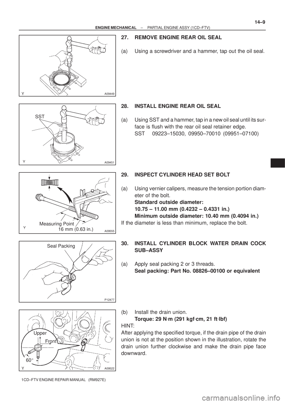
27. REMOVE ENGINE REAR OIL SEAL
(a) Using a screwdriver and a hammer, tap out the oil seal.
28. INSTALL ENGINE REAR OIL SEAL
(a) Using SST and a hammer, tap in a new oil seal until its sur-
face is flush with the rear oil seal retainer edge.
SST 09223±15030, 09950±70010 (09951±07100)
29. INSPECT CYLINDER HEAD SET BOLT
(a) Using vernier calipers, measure the tension portion diam-
eter of the bolt.
Standard outside diameter:
10.75 ± 11.00 mm (0.4232 ± 0.4331 in.)
Minimum outside diameter: 10.40 mm (0.4094 in.)
If the diameter is less than minimum, replace the bolt.
30. INSTALL CYLINDER BLOCK WATER DRAIN COCK
SUB±ASSY
(a) Apply seal packing 2 or 3 threads.
Seal packing: Part No. 08826±00100 or equivalent
(b) Install the drain union.
Torque: 29 N�m (291 kgf�cm, 21 ft�lbf)
HINT:
After applying the specified torque, if the drain pipe of the drain
union is not at the position shown in the illustration, rotate the
drain union further clockwise and make the drain pipe face
downward.
Page 52 of 136
A56696
A56704
Seal Width
4 ± 7 mmBA
A
B
A56706
Front
Measuring Point
A57100
Measuring Tip
Protrusion 14±12
± ENGINE MECHANICALPARTIAL ENGINE ASSY (1CD±FTV)
1CD±FTV ENGINE REPAIR MANUAL (RM927E)
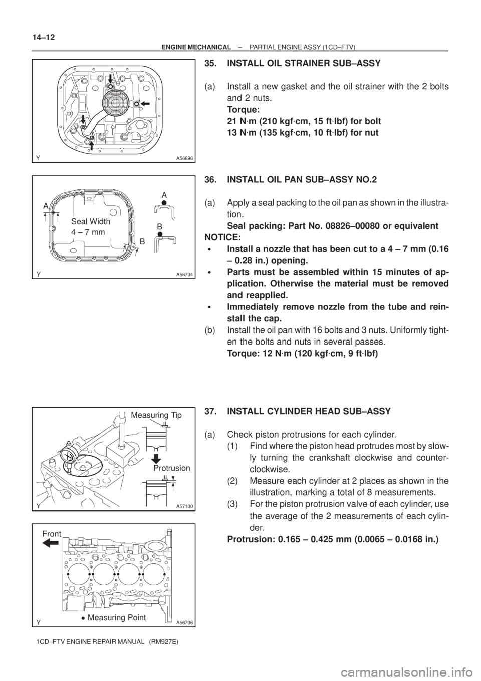
35. INSTALL OIL STRAINER SUB±ASSY
(a) Install a new gasket and the oil strainer with the 2 bolts
and 2 nuts.
Torque:
21 N�m (210 kgf�cm, 15 ft�lbf) for bolt
13 N�m (135 kgf�cm, 10 ft�lbf) for nut
36. INSTALL OIL PAN SUB±ASSY NO.2
(a) Apply a seal packing to the oil pan as shown in the illustra-
tion.
Seal packing: Part No. 08826±00080 or equivalent
NOTICE:
�Install a nozzle that has been cut to a 4 ± 7 mm (0.16
± 0.28 in.) opening.
�Parts must be assembled within 15 minutes of ap-
plication. Otherwise the material must be removed
and reapplied.
�Immediately remove nozzle from the tube and rein-
stall the cap.
(b) Install the oil pan with 16 bolts and 3 nuts. Uniformly tight-
en the bolts and nuts in several passes.
Torque: 12 N�m (120 kgf�cm, 9 ft�lbf)
37. INSTALL CYLINDER HEAD SUB±ASSY
(a) Check piston protrusions for each cylinder.
(1) Find where the piston head protrudes most by slow-
ly turning the crankshaft clockwise and counter-
clockwise.
(2) Measure each cylinder at 2 places as shown in the
illustration, marking a total of 8 measurements.
(3) For the piston protrusion valve of each cylinder, use
the average of the 2 measurements of each cylin-
der.
Protrusion: 0.165 ± 0.425 mm (0.0065 ± 0.0168 in.)
Page 89 of 136
A56041
A09474
A56038
± ENGINE MECHANICALCYLINDER BLOCK (1CD±FTV)
14±49
1CD±FTV ENGINE REPAIR MANUAL (RM927E)
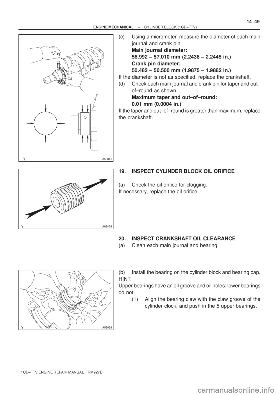
(c) Using a micrometer, measure the diameter of each main
journal and crank pin.
Main journal diameter:
56.992 ± 57.010 mm (2.2438 ± 2.2445 in.)
Crank pin diameter:
50.482 ± 50.500 mm (1.9875 ± 1.9882 in.)
If the diameter is not as specified, replace the crankshaft.
(d) Check each main journal and crank pin for taper and out±
of±round as shown.
Maximum taper and out±of±round:
0.01 mm (0.0004 in.)
If the taper and out±of±round is greater than maximum, replace
the crankshaft.
19. INSPECT CYLINDER BLOCK OIL ORIFICE
(a) Check the oil orifice for clogging.
If necessary, replace the oil orifice.
20. INSPECT CRANKSHAFT OIL CLEARANCE
(a) Clean each main journal and bearing.
(b) Install the bearing on the cylinder block and bearing cap.
HINT:
Upper bearings have an oil groove and oil holes; lower bearings
do not.
(1) Align the bearing claw with the claw groove of the
cylinder clock, and push in the 5 upper bearings.
Page 106 of 136
A55621
A55622
A55623
A55624
Free
Lock
A55625
Terminal 50 Terminal C
± STARTING & CHARGINGSTARTER ASSY(1.4KW) (1CD±FTV)
19±5
1CD±FTV ENGINE REPAIR MANUAL (RM927E)
(c) Using vernier calipers, measure the brush length.
Standard length: 15.5 mm (0.6102 in.)
Minimum length: 8.5 mm (0.3346 in.)
7. INSPECT STARTER BRUSH HOLDER ASSY
(a) Using an ohmmeter, check that there is no continuity be-
tween the positive (+) and negative (±) brush holders.
(b) Using vernier calipers, measure the brush length.
Standard length: 15.5 mm (0.6102 in.)
Minimum length: 8.5 mm (0.3346 in.)
8. INSPECT STARTER CLUTCH SUB±ASSY
(a) Rotate the pinion gear clockwise, and check that it turns
freely. Try to rotate the pinion gear counterclockwise and
check that it locks.
9. INSPECT MAGNET STARTER SWITCH ASSY
(a) Using an ohmmeter, check that there is continuity be-
tween terminal 50 and C.
Page 113 of 136
A62964
A62965
A62966
A62967
Free
Lock 19±12
± STARTING & CHARGINGSTARTER ASSY(2.0KW) (1CD±FTV)
1CD±FTV ENGINE REPAIR MANUAL (RM927E)
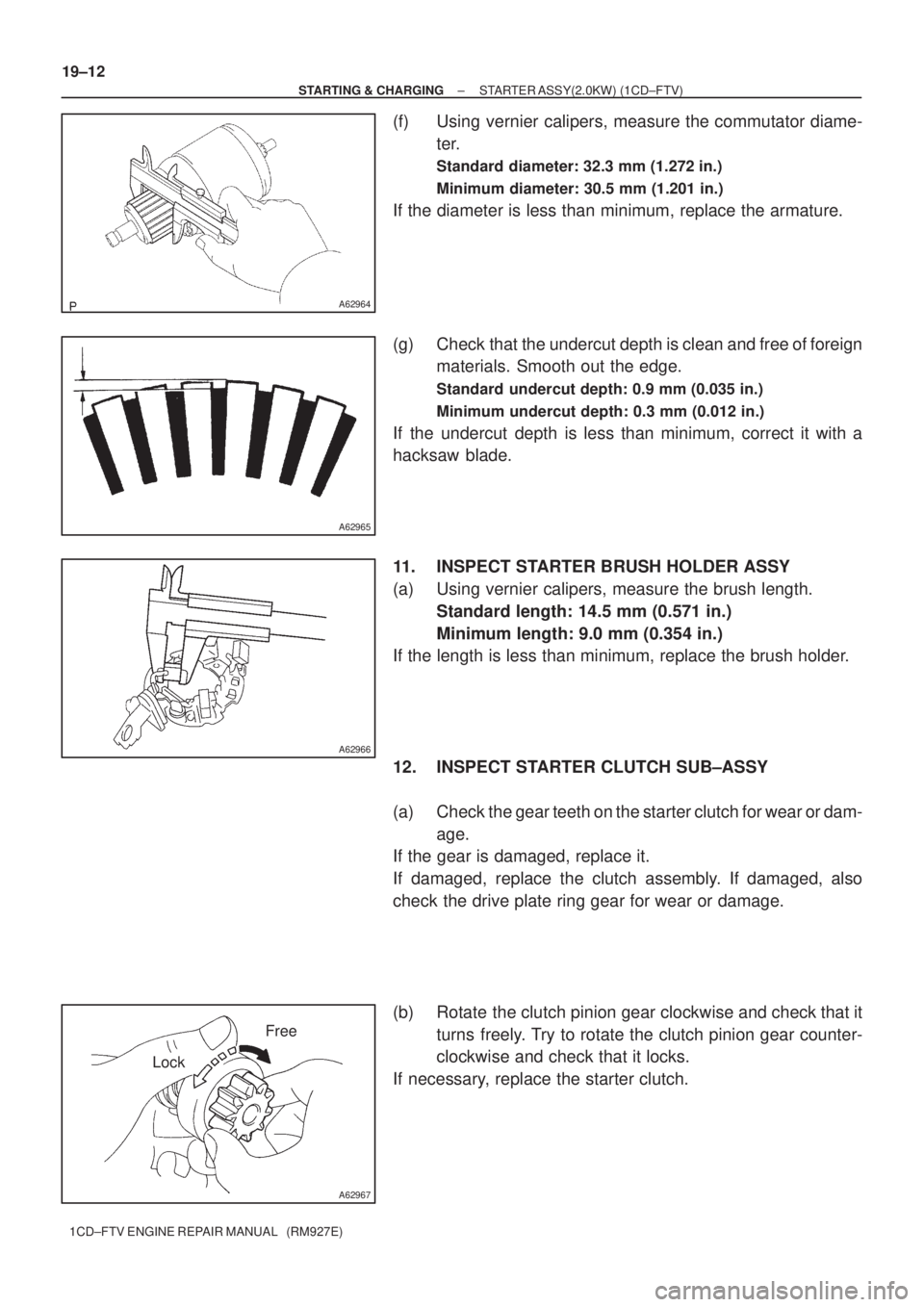
(f) Using vernier calipers, measure the commutator diame-
ter.
Standard diameter: 32.3 mm (1.272 in.)
Minimum diameter: 30.5 mm (1.201 in.)
If the diameter is less than minimum, replace the armature.
(g) Check that the undercut depth is clean and free of foreign
materials. Smooth out the edge.
Standard undercut depth: 0.9 mm (0.035 in.)
Minimum undercut depth: 0.3 mm (0.012 in.)
If the undercut depth is less than minimum, correct it with a
hacksaw blade.
11. INSPECT STARTER BRUSH HOLDER ASSY
(a) Using vernier calipers, measure the brush length.
Standard length: 14.5 mm (0.571 in.)
Minimum length: 9.0 mm (0.354 in.)
If the length is less than minimum, replace the brush holder.
12. INSPECT STARTER CLUTCH SUB±ASSY
(a) Check the gear teeth on the starter clutch for wear or dam-
age.
If the gear is damaged, replace it.
If damaged, replace the clutch assembly. If damaged, also
check the drive plate ring gear for wear or damage.
(b) Rotate the clutch pinion gear clockwise and check that it
turns freely. Try to rotate the clutch pinion gear counter-
clockwise and check that it locks.
If necessary, replace the starter clutch.
Page 122 of 136
A55642
A55643
A55624
Free
Lock
B55687
Terminal 50
Terminal C
B55691
Terminal 50
Switch Body
± STARTING & CHARGINGSTARTER ASSY(2.2KW) (1CD±FTV)
19±21
1CD±FTV ENGINE REPAIR MANUAL (RM927E)
7. INSPECT STARTER BRUSH HOLDER ASSY
(a) Using an ohmmeter, check that there is no continuity be-
tween the positive (+) and negative (±) brush holders.
(b) Using vernier calipers, measure the brush length.
Standard length: 16.5 mm (0.6496 in.)
Minimum length: 9 mm (0.3543 in.)
8. INSPECT STARTER CLUTCH SUB±ASSY
(a) Rotate the pinion gear clockwise, and check that it turns
freely. Try to rotate the pinion gear counterclockwise and
check that it locks.
9. INSPECT MAGNET STARTER SWITCH ASSY
(a) Using an ohmmeter, check that there is continuity be-
tween terminals 50 and C.
(b) Using an ohmmeter, check that there is continuity be-
tween terminal 50 and the switch body.
Page 126 of 136
19095±02
A38024
A38025
SST 1 ± A
A38104
A38105
± STARTING & CHARGINGGENERATOR ASSY(90A) (1CD±FTV)
19±25
1CD±FTV ENGINE REPAIR MANUAL (RM927E)
OVERHAUL
1. REMOVE GENERATOR PULLEY
SST 09820±63010 (09820±06010, 09820±06020)
HINT:
SST1 ± A, B09820±06010
SST209820±06020
(a) Hold SST 1 ± A with a torque wrench, and tighten SST 1
± B clockwise to the specified torque.
Torque: 39 N�m (400 kgf�cm, 29 ft�lbf)
NOTICE:
Check that SST is secured to the rotor shaft.
(b) Mount SST 2 in a vise.
(c) Insert SST 1 ± A, B into SST 2, and attach the pulley nut
to SST 2.
(d) To loosen the pulley nut, turn SST 1 ± A in the direction
shown in the illustration.
NOTICE:
To prevent damage to the rotor shaft, do not loosen the
pulley nut more than one±half of a turn.
(e) Remove the alternator form SST 2.
(f) Turn SST 1 ± B, and remove SST 1 ± A, B.
(g) Remove the pulley nut and pulley.
Page 130 of 136
Upward
A51919
A38024
± STARTING & CHARGINGGENERATOR ASSY(90A) (1CD±FTV)
19±29
1CD±FTV ENGINE REPAIR MANUAL (RM927E)
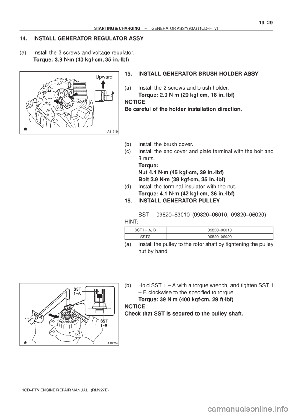
14. INSTALL GENERATOR REGULATOR ASSY
(a) Install the 3 screws and voltage regulator.
Torque: 3.9 N�m (40 kgf�cm, 35 in.�lbf)
15. INSTALL GENERATOR BRUSH HOLDER ASSY
(a) Install the 2 screws and brush holder.
Torque: 2.0 N�m (20 kgf�cm, 18 in.�lbf)
NOTICE:
Be careful of the holder installation direction.
(b) Install the brush cover.
(c) Install the end cover and plate terminal with the bolt and
3 nuts.
Torque:
Nut 4.4 N�m (45 kgf�cm, 39 in.�lbf)
Bolt 3.9 N�m (39 kgf�cm, 35 in.�lbf)
(d) Install the terminal insulator with the nut.
Torque: 4.1 N�m (42 kgf�cm, 36 in.�lbf)
16. INSTALL GENERATOR PULLEY
SST 09820±63010 (09820±06010, 09820±06020)
HINT:
SST1 ± A, B09820±06010
SST209820±06020
(a) Install the pulley to the rotor shaft by tightening the pulley
nut by hand.
(b) Hold SST 1 ± A with a torque wrench, and tighten SST 1
± B clockwise to the specified to torque.
Torque: 39 N�m (400 kgf�cm, 29 ft�lbf)
NOTICE:
Check that SST is secured to the pulley shaft.