Page 113 of 136

A62964
A62965
A62966
A62967
Free
Lock 19±12
± STARTING & CHARGINGSTARTER ASSY(2.0KW) (1CD±FTV)
1CD±FTV ENGINE REPAIR MANUAL (RM927E)
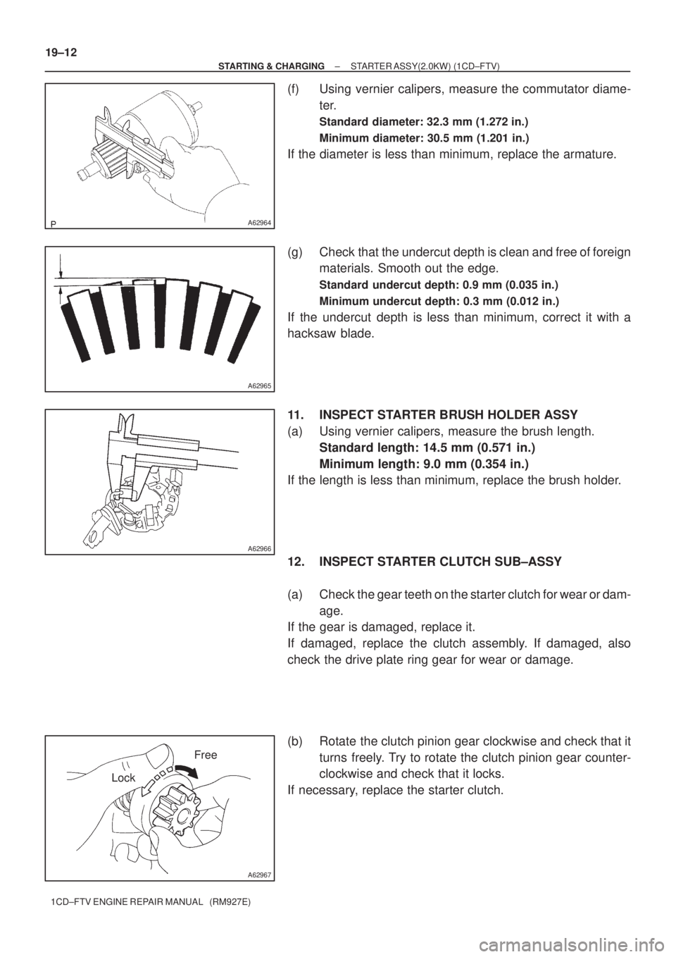
(f) Using vernier calipers, measure the commutator diame-
ter.
Standard diameter: 32.3 mm (1.272 in.)
Minimum diameter: 30.5 mm (1.201 in.)
If the diameter is less than minimum, replace the armature.
(g) Check that the undercut depth is clean and free of foreign
materials. Smooth out the edge.
Standard undercut depth: 0.9 mm (0.035 in.)
Minimum undercut depth: 0.3 mm (0.012 in.)
If the undercut depth is less than minimum, correct it with a
hacksaw blade.
11. INSPECT STARTER BRUSH HOLDER ASSY
(a) Using vernier calipers, measure the brush length.
Standard length: 14.5 mm (0.571 in.)
Minimum length: 9.0 mm (0.354 in.)
If the length is less than minimum, replace the brush holder.
12. INSPECT STARTER CLUTCH SUB±ASSY
(a) Check the gear teeth on the starter clutch for wear or dam-
age.
If the gear is damaged, replace it.
If damaged, replace the clutch assembly. If damaged, also
check the drive plate ring gear for wear or damage.
(b) Rotate the clutch pinion gear clockwise and check that it
turns freely. Try to rotate the clutch pinion gear counter-
clockwise and check that it locks.
If necessary, replace the starter clutch.
Page 114 of 136

A62968
Return
A63797
Terminal C Terminal 50
Continuity
A63798
Switch Body
Terminal 50
Continuity
A63799
Turn
± STARTING & CHARGINGSTARTER ASSY(2.0KW) (1CD±FTV)
19±13
1CD±FTV ENGINE REPAIR MANUAL (RM927E)
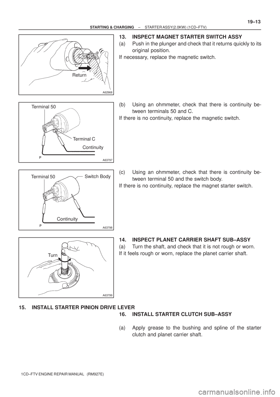
13. INSPECT MAGNET STARTER SWITCH ASSY
(a) Push in the plunger and check that it returns quickly to its
original position.
If necessary, replace the magnetic switch.
(b) Using an ohmmeter, check that there is continuity be-
tween terminals 50 and C.
If there is no continuity, replace the magnetic switch.
(c) Using an ohmmeter, check that there is continuity be-
tween terminal 50 and the switch body.
If there is no continuity, replace the magnet starter switch.
14. INSPECT PLANET CARRIER SHAFT SUB±ASSY
(a) Turn the shaft, and check that it is not rough or worn.
If it feels rough or worn, replace the planet carrier shaft.
15. INSTALL STARTER PINION DRIVE LEVER
16. INSTALL STARTER CLUTCH SUB±ASSY
(a) Apply grease to the bushing and spline of the starter
clutch and planet carrier shaft.
Page 115 of 136
A63800
A63801
A63802
A63803
Knock
Pin Hole
Drive Housing
Knock Pin
Drive Lever
A63804
Rubber Cushion
19±14
± STARTING & CHARGINGSTARTER ASSY(2.0KW) (1CD±FTV)
1CD±FTV ENGINE REPAIR MANUAL (RM927E)
(b) Place the starter clutch and stop collar on the planet carri-
er shaft as shown in the illustration.
(c) Install a new snap ring to the planet carrier shaft groove.
(d) Using a vise, compress the snap ring.
(e) Check that the snap ring fits correctly.
(f) Using a screwdriver, tap the stop collar to slide it onto the
snap ring.
17. INSTALL PLANET CARRIER SHAFT SUB±ASSY
(a) Set the planet carrier shaft and drive lever in position as
shown in the illustration.
(b) Align the holes of the drive housing with the knock pins.
(c) Install the planet carrier shaft and starter clutch to the
drive housing.
(d) Install the rubber cushion.
Page 116 of 136
A63805
SST
A63806
SST
A63807
SST
A63808
A63809
± STARTING & CHARGINGSTARTER ASSY(2.0KW) (1CD±FTV)
19±15
1CD±FTV ENGINE REPAIR MANUAL (RM927E)
18. INSTALL STARTER BRUSH HOLDER ASSY
(a) Install the 4 brush retainers and 4 brush springs to the
brush holder.
(b) Using SST, install the 4 brushes to the brush holder.
SST 09950±60010 (09951±00340)
(c) Attach the brush holder to the armature.
(d) Push the armature, and remove the SST.
19. INSTALL STARTER YOKE ASSY
(a) Align the cushion rubber on the starter drive housing with
the cutout of the starter yoke.
(b) Install the starter yoke and armature assembly.
(c) Align the commutator end frame with the brush holder
rubber part as shown in the illustration.
(d) Install the commutator end frame with the 2 through bolts.
6.5 N´m (66 kgf´cm, 58 in.´lbf)
Page 117 of 136
A63810
A62724
A63811
A62722
19±16
±
STARTING & CHARGING STARTER ASSY(2.0KW) (1CD±FTV)
1CD±FTV ENGINE REPAIR MANUAL (RM927E)
20. I N S TA L L S TA R T E R C O M M U TATO R E N D F R A M COVER
(a) Install the thrust washer and lock plate.
(b) Check the armature thrust clearance between the lock
plate and the end frame cover. (See page 19±9)
(c) Pack grease to the commutator end cover.
(d) Install the commutator end fram cover with the 2 screws.
1.7 N´m (17 kgf´cm, 15 in.´lbf)
21. INSTALL MAGNET STARTER SWITCH ASSY
(a) Hang the plunger hook to the upper side of the drive lever.
(b) Install the return spring into the plunger.
(c) Install the return spring and magnet sarter switch with the 3 screws.
5.0 N´m (51 kgf´cm, 44 in.´lbf)
(d) Connect the lead wire to the magnet starter switch termi-nal with the nut.
8.0 N´m (82 kgf´cm, 71 in.´lbf)
Page 118 of 136
190AH±01
A62713
Starter Yoke Assy
Starter Brush Holder AssyStarter Armature Assy
Drive Housing
Starter Clutch Sub±Assy Ball
Spring
Magnetic Switch
5.9 (60, 52 in.´lbf)
N´m (kgf´cm, ft´lbf)
: Specified torque
9.3 (95, 82 in.´lbf)
12.7 (130, 9.0 )
12.7 (130, 9.0 )
9.3 (95, 82 in.´lbf)
± STARTING & CHARGINGSTARTER ASSY(2.2KW) (1CD±FTV)
19±17
1CD±FTV ENGINE REPAIR MANUAL (RM927E)
STARTER ASSY(2.2KW) (1CD±FTV)
COMPONENTS
Page 119 of 136
1906H±02
A55633
B13607
A55635
A55636
Magnetic Finger
19±18
± STARTING & CHARGINGSTARTER ASSY(2.2KW) (1CD±FTV)
1CD±FTV ENGINE REPAIR MANUAL (RM927E)
OVERHAUL
1. REMOVE STARTER YOKE ASSY
(a) Remove the nut, and disconnect the lead wire from the
magnetic switch terminal.
(b) Remove the 2 through bolts.
(c) Pull out the yoke together with the armature from the mag-
netic switch.
2. REMOVE STARTER CLUTCH SUB±ASSY
(a) Remove the 2 bolts and drive housing.
(b) Remove the clutch from the drive housing
(c) Using a magnetic finger, remove the ball from the clutch
shaft hole.
Page 120 of 136
A51182
A51183
A55637
A55638
A51186
± STARTING & CHARGINGSTARTER ASSY(2.2KW) (1CD±FTV)
19±19
1CD±FTV ENGINE REPAIR MANUAL (RM927E)
3. REMOVE STARTER BRUSH HOLDER ASSY
(a) Using a screwdriver, hold the spring back disconnect the
brush from the brush holder. Disconnect the 4 brushers
and remove the brush holder.
4. REMOVE STARTER ARMATURE ASSY
(a) Using a plastic±faced hammer, tap the yoke and remove
the armature.
5. INSPECT STARTER ARMATURE ASSY
(a) Using an ohmmeter, check that there is continuity be-
tween the segments of the commutator.
(b) Using an ohmmeter, check that there is no continuity be-
tween the commutator and armature coil core.
(c) Place the commutator on V±blocks.
(d) Using a dial gauge, measure the circle runout.
Maximum circle runout: 0.05 mm (0.002 in.)