Page 121 of 136
A51187
A51188
A55639
A55640
A55641
19±20
± STARTING & CHARGINGSTARTER ASSY(2.2KW) (1CD±FTV)
1CD±FTV ENGINE REPAIR MANUAL (RM927E)
(e) Using vernier calipers, measure the commutator diame-
ter.
Standard diameter: 35 mm (1.378 in.)
Minimum diameter: 34 mm (1.3386 in.)
(f) Check that the undercut depth is clean and free of foreign
materials. Smooth out the edge.
Standard undercut depth: 0.7 mm (0.0276 in.)
Minimum undercut depth: 0.2 mm (0.079 in.)
6. INSPECT STARTER YOKE ASSY
(a) Using an ohmmeter, check that there is continuity be-
tween the lead wire and field coil brush lead.
(b) Using an ohmmeter, check that there is no continuity be-
tween the field coil brush lead and yoke.
(c) Using vernier calipers, measure the brush length.
Standard length: 16.5 mm (0.6496 in.)
Minimum length: 9 mm (0.3543 in.)
Page 122 of 136
A55642
A55643
A55624
Free
Lock
B55687
Terminal 50
Terminal C
B55691
Terminal 50
Switch Body
± STARTING & CHARGINGSTARTER ASSY(2.2KW) (1CD±FTV)
19±21
1CD±FTV ENGINE REPAIR MANUAL (RM927E)
7. INSPECT STARTER BRUSH HOLDER ASSY
(a) Using an ohmmeter, check that there is no continuity be-
tween the positive (+) and negative (±) brush holders.
(b) Using vernier calipers, measure the brush length.
Standard length: 16.5 mm (0.6496 in.)
Minimum length: 9 mm (0.3543 in.)
8. INSPECT STARTER CLUTCH SUB±ASSY
(a) Rotate the pinion gear clockwise, and check that it turns
freely. Try to rotate the pinion gear counterclockwise and
check that it locks.
9. INSPECT MAGNET STARTER SWITCH ASSY
(a) Using an ohmmeter, check that there is continuity be-
tween terminals 50 and C.
(b) Using an ohmmeter, check that there is continuity be-
tween terminal 50 and the switch body.
Page 123 of 136
A51212
A55483
A55646
A55635
B13607
19±22
± STARTING & CHARGINGSTARTER ASSY(2.2KW) (1CD±FTV)
1CD±FTV ENGINE REPAIR MANUAL (RM927E)
10. INSTALL STARTER ARMATURE ASSY
(a) Apply grease to the armature bearings.
(b) Using a press, press in armature.
11. INSTALL STARTER BRUSH HOLDER ASSY
(a) Align the claw of the brush holder with the claw groove of
the yoke.
(b) Place the brush on the yoke.
(c) Using a screwdriver, hold the brush spring back and con-
nect the brush into the brush holder. Connect the 4
brushes.
NOTICE:
Check that the positive (+) lead wires are not grounded.
12. INSTALL STARTER CLUTCH SUB±ASSY
(a) Apply grease to the ball.
(b) Insert the ball into the clutch shaft hole.
(c) Place the clutch on the drive housing.
(d) Install the drive housing to the magnetic switch with the
2 bolts.
Torque: 9.3 N�m (95 kgf�cm, 82 in.�lbf)
Page 124 of 136
A55647
A55633
± STARTING & CHARGINGSTARTER ASSY(2.2KW) (1CD±FTV)
19±23
1CD±FTV ENGINE REPAIR MANUAL (RM927E)
13. INSTALL STARTER YOKE ASSY
(a) Align the claws of the brush holder with the grooves of the
magnetic switch, and install the yoke and armature.
(b) Align the punch mark of the yoke with the line of the mag-
netic switch.
(c) Install the yoke and armature with the 2 through bolts.
Torque: 12.7 N�m (130 kgf�cm, 9 ft�lbf)
(d) Connect the lead wire to terminal C with the nut.
Torque: 5.9 N�m (60 kgf�cm, 52 in.�lbf)
Page 125 of 136
19094±02
A59147
PulleyDrive End FrameRotor
Alternator Washer
Rectifier End Frame
Voltage Regulator Brush Holder Cover
Brush HolderRear End Cover
N´m (kgf´cm, ft´lbf)
: Specified torque
111 (1125, 81)
Rectifier Holder
19±24
± STARTING & CHARGINGGENERATOR ASSY(90A) (1CD±FTV)
1CD±FTV ENGINE REPAIR MANUAL (RM927E)
GENERATOR ASSY(90A) (1CD±FTV)
COMPONENTS
Page 126 of 136
19095±02
A38024
A38025
SST 1 ± A
A38104
A38105
± STARTING & CHARGINGGENERATOR ASSY(90A) (1CD±FTV)
19±25
1CD±FTV ENGINE REPAIR MANUAL (RM927E)
OVERHAUL
1. REMOVE GENERATOR PULLEY
SST 09820±63010 (09820±06010, 09820±06020)
HINT:
SST1 ± A, B09820±06010
SST209820±06020
(a) Hold SST 1 ± A with a torque wrench, and tighten SST 1
± B clockwise to the specified torque.
Torque: 39 N�m (400 kgf�cm, 29 ft�lbf)
NOTICE:
Check that SST is secured to the rotor shaft.
(b) Mount SST 2 in a vise.
(c) Insert SST 1 ± A, B into SST 2, and attach the pulley nut
to SST 2.
(d) To loosen the pulley nut, turn SST 1 ± A in the direction
shown in the illustration.
NOTICE:
To prevent damage to the rotor shaft, do not loosen the
pulley nut more than one±half of a turn.
(e) Remove the alternator form SST 2.
(f) Turn SST 1 ± B, and remove SST 1 ± A, B.
(g) Remove the pulley nut and pulley.
Page 127 of 136

SST
Wooden block
A51918
A59143
F
B
Ohmmeter 19±26
± STARTING & CHARGINGGENERATOR ASSY(90A) (1CD±FTV)
1CD±FTV ENGINE REPAIR MANUAL (RM927E)
2. REMOVE GENERATOR BRUSH HOLDER ASSY
(a) Remove the nut and terminal insulator.
(b) Remove the bolt, 3 nuts, plate terminal and end cover.
(c) Remove the brush cover.
(d) Remove the 2 screws and brush holder.
3. REMOVE GENERATOR REGULATOR ASSY
(a) Remove the 3 screws and voltage regulator.
4. REMOVE GENERATOR HOLDER W/RECTIFIER
(a) Remove the 4 screws and rectifier holder.
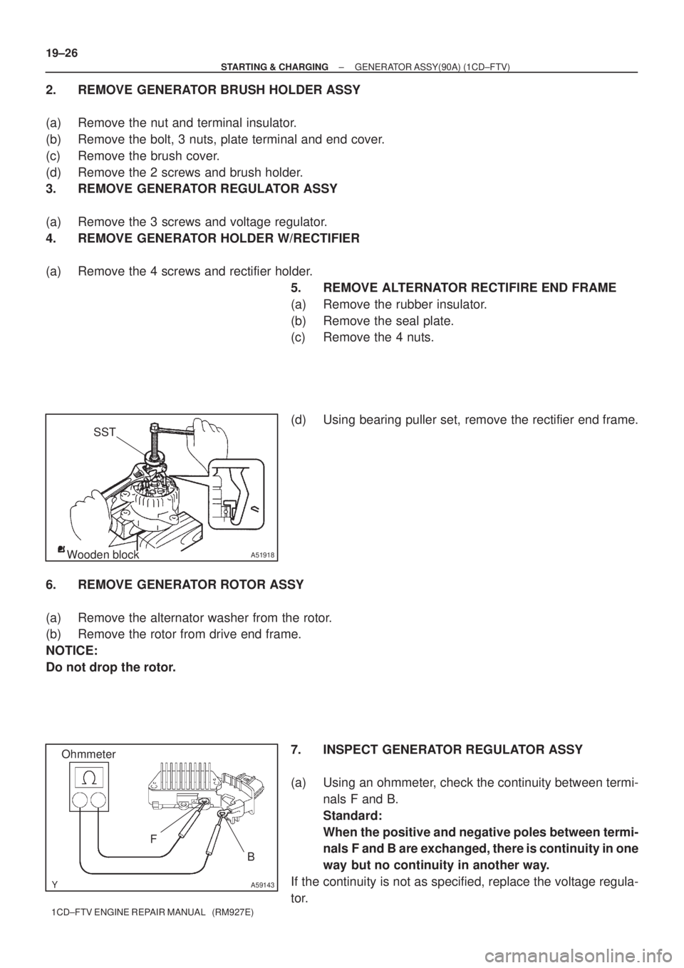
5. REMOVE ALTERNATOR RECTIFIRE END FRAME
(a) Remove the rubber insulator.
(b) Remove the seal plate.
(c) Remove the 4 nuts.
(d) Using bearing puller set, remove the rectifier end frame.
6. REMOVE GENERATOR ROTOR ASSY
(a) Remove the alternator washer from the rotor.
(b) Remove the rotor from drive end frame.
NOTICE:
Do not drop the rotor.
7. INSPECT GENERATOR REGULATOR ASSY
(a) Using an ohmmeter, check the continuity between termi-
nals F and B.
Standard:
When the positive and negative poles between termi-
nals F and B are exchanged, there is continuity in one
way but no continuity in another way.
If the continuity is not as specified, replace the voltage regula-
tor.
Page 128 of 136

A59144
E
F
Ohmmeter
A38108
A38109
A38110
�
B
P
1
P2P3
P4
EP
4P2P1
B
A36999
± STARTING & CHARGINGGENERATOR ASSY(90A) (1CD±FTV)
19±27
1CD±FTV ENGINE REPAIR MANUAL (RM927E)
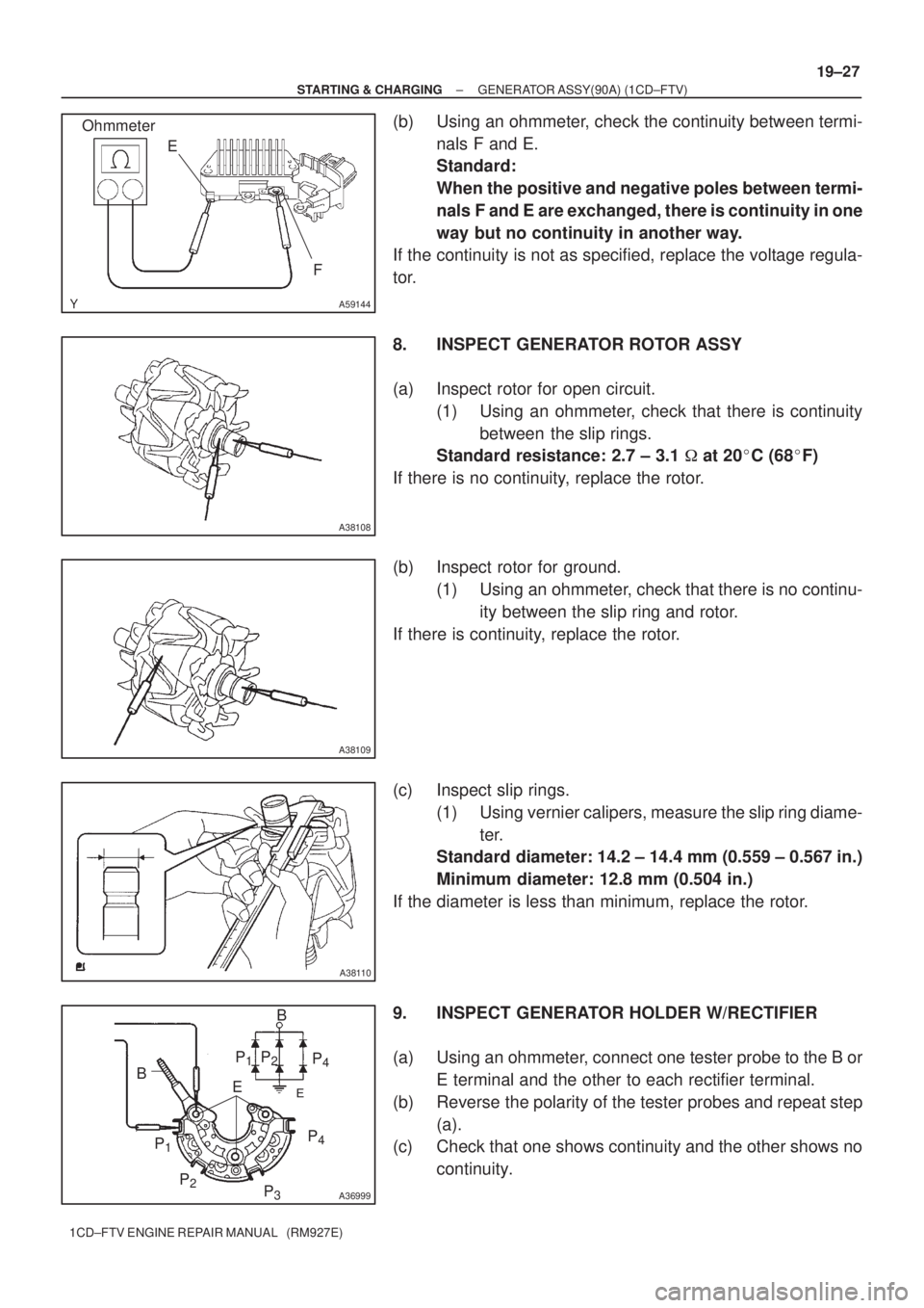
(b) Using an ohmmeter, check the continuity between termi-
nals F and E.
Standard:
When the positive and negative poles between termi-
nals F and E are exchanged, there is continuity in one
way but no continuity in another way.
If the continuity is not as specified, replace the voltage regula-
tor.
8. INSPECT GENERATOR ROTOR ASSY
(a) Inspect rotor for open circuit.
(1) Using an ohmmeter, check that there is continuity
between the slip rings.
Standard resistance: 2.7 ± 3.1 � at 20�C (68�F)
If there is no continuity, replace the rotor.
(b) Inspect rotor for ground.
(1) Using an ohmmeter, check that there is no continu-
ity between the slip ring and rotor.
If there is continuity, replace the rotor.
(c) Inspect slip rings.
(1) Using vernier calipers, measure the slip ring diame-
ter.
Standard diameter: 14.2 ± 14.4 mm (0.559 ± 0.567 in.)
Minimum diameter: 12.8 mm (0.504 in.)
If the diameter is less than minimum, replace the rotor.
9. INSPECT GENERATOR HOLDER W/RECTIFIER
(a) Using an ohmmeter, connect one tester probe to the B or
E terminal and the other to each rectifier terminal.
(b) Reverse the polarity of the tester probes and repeat step
(a).
(c) Check that one shows continuity and the other shows no
continuity.