2004 SUBARU FORESTER wheel
[x] Cancel search: wheelPage 1047 of 2870
LU(H4SO)-19
LUBRICATION
Oil Pan and Strainer
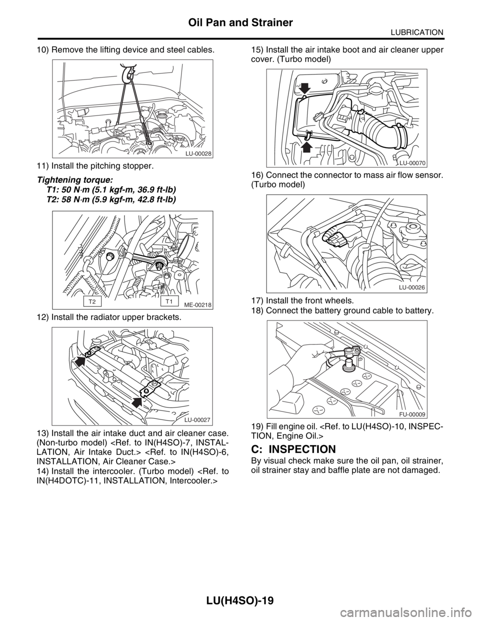
10) Remove the lifting device and steel cables.
11) Install the pitching stopper.
Tightening torque:
T1: 50 N
⋅m (5.1 kgf-m, 36.9 ft-lb)
T2: 58 N
⋅m (5.9 kgf-m, 42.8 ft-lb)
12) Install the radiator upper brackets.
13) Install the air intake duct and air cleaner case.
(Non-turbo model)
14) Install the intercooler. (Turbo model)
cover. (Turbo model)
16) Connect the connector to mass air flow sensor.
(Turbo model)
17) Install the front wheels.
18) Connect the battery ground cable to battery.
19) Fill engine oil.
C: INSPECTION
By visual check make sure the oil pan, oil strainer,
oil strainer stay and baffle plate are not damaged.
LU-00028
ME-00218T2T1
LU-00027
LU-00070
LU-00026
FU-00009
Page 1105 of 2870
EN(H4SO)-7
ENGINE (DIAGNOSTIC)
General Description
The antenna feeder must be placed as far
apart as possible from the ECM and MFI har-
ness.
Carefully adjust the antenna for correct
matching.
When mounting a large power type radio, pay
special attention to the three items above men-
tioned.
Incorrect installation of the radio may affect
the operation of the ECM.
13) Before disconnecting the fuel hose, disconnect
the fuel pump connector and crank the engine for
more than five seconds to release pressure in the
fuel system. If engine starts during this operation,
run it until it stops.
14) Problems in the electronic-controlled automatic
transmission may be caused by failure of the en-
gine, the electronic control system, the transmis-
sion proper, or by a combination of these. These
three causes must be distinguished clearly when
performing diagnostics.
15) Diagnostics should be conducted by rotating
with simple, easy operations and proceeding to
complicated, difficult operations. The most impor-
tant thing in diagnostics is to understand the cus-
tomer’s complaint, and distinguish between the
three causes.
16) In AT models, do not continue the stall for more
than five seconds. (from closed throttle, fully open
throttle to stall engine speed.)
17) On the model with ABS, when performing driv-
ing test in jacked-up or lifted-up position, some-
times the warning light may be lit, but this is not a
malfunction of the system. The reason for this is the
speed difference between the front and rear
wheels. After diagnosis of engine control system,
perform the ABS memory clearance procedure of
self-diagnosis function.
B: INSPECTION
Before performing diagnostics, check the following
items which might affect engine problems:
1. BATTERY
1) Measure battery voltage and specific gravity of
electrolyte.
Standard voltage: 12 V
Specific gravity: Above 1.260
2) Check the condition of the main and other fuses,
and harnesses and connectors. Also check for
proper grounding.
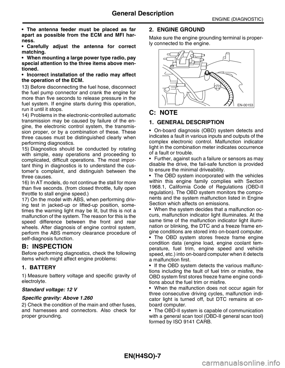
2. ENGINE GROUND
Make sure the engine grounding terminal is proper-
ly connected to the engine.
C: NOTE
1. GENERAL DESCRIPTION
On-board diagnosis (OBD) system detects and
indicates a fault in various inputs and outputs of the
complex electronic control. Malfunction indicator
light in the combination meter indicates occurrence
of a fault or trouble.
Further, against such a failure or sensors as may
disable the drive, the fail-safe function is provided
to ensure the minimal driveability.
The OBD system incorporated with the vehicles
within this engine family complies with Section
1968.1, California Code of Regulations (OBD-II
regulation). The OBD system monitors the compo-
nents and the system malfunction listed in Engine
Section which affects on emissions.
When the system decides that a malfunction oc-
curs, malfunction indicator light illuminates. At the
same time of the malfunction indicator light illumi-
nation or blinking, the DTC and a freeze frame en-
gine conditions are stored into on-board computer.
The OBD system stores freeze frame engine
condition data (engine load, engine coolant tem-
perature, fuel trim, engine speed and vehicle
speed, etc.) into on-board computer when it detects
a malfunction first.
If the OBD system detects the various malfunc-
tions including the fault of fuel trim or misfire, the
OBD system first stores freeze frame engine condi-
tions about the fuel trim or misfire.
When the malfunction does not occur again for
three consecutive driving cycles, malfunction indi-
cator light is turned off, but DTC remains at on-
board computer.
The OBD-II system is capable of communication
with a general scan tool (OBD-II general scan tool)
formed by ISO 9141 CARB.
EN-00153
Page 1133 of 2870
![SUBARU FORESTER 2004 Service Repair Manual EN(H4SO)-35
ENGINE (DIAGNOSTIC)
Subaru Select Monitor
8. READ CURRENT DATA FOR AT
1) On the «Main Menu» display screen, select the {Each System Check} and press the [YES] key.
2) On the «System Sel SUBARU FORESTER 2004 Service Repair Manual EN(H4SO)-35
ENGINE (DIAGNOSTIC)
Subaru Select Monitor
8. READ CURRENT DATA FOR AT
1) On the «Main Menu» display screen, select the {Each System Check} and press the [YES] key.
2) On the «System Sel](/manual-img/17/57426/w960_57426-1132.png)
EN(H4SO)-35
ENGINE (DIAGNOSTIC)
Subaru Select Monitor
8. READ CURRENT DATA FOR AT
1) On the «Main Menu» display screen, select the {Each System Check} and press the [YES] key.
2) On the «System Selection Menu» display screen, select the {Transmission} and press the [YES] key.
3) Press the [YES] key after the information of transmission type is displayed.
4) On the «Transmission Diagnosis» display screen, select the {Current Data Display & Save} and press the
[YES] key.
5) On the «Transmission Diagnosis» display screen, select the {Data Display} and press the [YES] key.
6) Using the scroll key, scroll the display screen up or down until the desired data is shown.
A list of the support data is shown in the following table.
Description Display Unit of measure
Battery voltage Battery Voltage V
Rear vehicle speed sensor signal Rear Wheel Speed km/h or MPH
Front vehicle speed sensor signal Front Wheel Speed km/h or MPH
Engine speed signal Engine speed rpm
ATF temperature signal ATF Temp.°C or °F
Throttle position sensor Throttle Sensor Voltage V
Gear Position Gear position —
Line pressure control duty ratio Line pressure duty %
Lock up clutch control duty ratio L/U Duty %
Transfer clutch control duty ratio AWD duty %
Throttle position sensor power supply Throttle sensor power supply V
Turbine revolution signal Turbine Revolution Speed rpm
2-4 Brake timing pressure control duty ratio 2-4 B Pressure Duty %
Intake manifold pressure sensor voltage Mani. Relative Voltage V
FWD switch signal FWD SW ON or OFF
Kick down switch signal Kick Down Switch ON or OFF
Stop light switch signal Stop Light SW ON or OFF
Anti lock brake system signal ABS signal ON or OFF
Cruise control system signal Cruise Control Signal ON or OFF
Neutral/Parking range signal N/P range ON or OFF
Reverse range signal R Range ON or OFF
Drive range signal D Range ON or OFF
3rd range signal 3rd Range Signal ON or OFF
2nd range signal 2nd Range Signal ON or OFF
1st range signal 1st Range Signal ON or OFF
Shift control solenoid A Shift Solenoid #1 ON or OFF
Shift control solenoid B Shift Solenoid #2 ON or OFF
Torque control output signal #1 Torque control output signal 1 ON or OFF
Torque control output signal #2 Torque control output signal 2 ON or OFF
Torque control cut signal Torque Control Cut Sig ON or OFF
2-4 brake timing control solenoid valve 2-4B Timing Solenoid ON or OFF
Low clutch timing control solenoid valve L/C timing solenoid ON or OFF
Automatic transmission diagnosis light output signal Diagnosis Lamp ON or OFF
Page 1137 of 2870
EN(H4SO)-39
ENGINE (DIAGNOSTIC)
Inspection Mode
1. PREPARATION FOR THE INSPECTION
MODE
1) Check battery voltage is more than 12 V and fuel
remains half [20 — 402 (5.3 — 10.6 US gal, 4.4 —
8.8 Imp gal)].
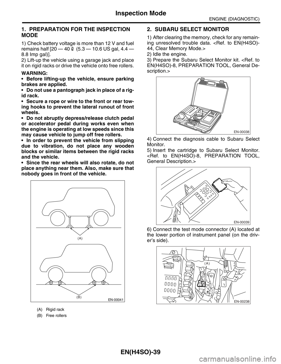
2) Lift-up the vehicle using a garage jack and place
it on rigid racks or drive the vehicle onto free rollers.
WARNING:
Before lifting-up the vehicle, ensure parking
brakes are applied.
Do not use a pantograph jack in place of a rig-
id rack.
Secure a rope or wire to the front or rear tow-
ing hooks to prevent the lateral runout of front
wheels.
Do not abruptly depress/release clutch pedal
or accelerator pedal during works even when
the engine is operating at low speeds since this
may cause vehicle to jump off free rollers.
In order to prevent the vehicle from slipping
due to vibration, do not place any wooden
blocks or similar items between the rigid racks
and the vehicle.
Since the rear wheels will also rotate, do not
place anything near them. Also, make sure that
nobody goes in front of the vehicle.
2. SUBARU SELECT MONITOR
1) After clearing the memory, check for any remain-
ing unresolved trouble data.
2) Idle the engine.
3) Prepare the Subaru Select Monitor kit.
scription.>
4) Connect the diagnosis cable to Subaru Select
Monitor.
5) Insert the cartridge to Subaru Select Monitor.
6) Connect the test mode connector (A) located at
the lower portion of instrument panel (on the driv-
er’s side).
(A) Rigid rack
(B) Free rollers
EN-00041
(A)
(B)
EN-00038
EN-00039
EN-00238
(A)
Page 1138 of 2870
EN(H4SO)-40
ENGINE (DIAGNOSTIC)
Inspection Mode
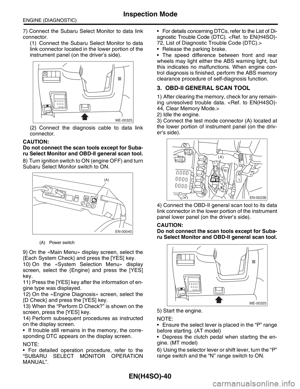
7) Connect the Subaru Select Monitor to data link
connector.
(1) Connect the Subaru Select Monitor to data
link connector located in the lower portion of the
instrument panel (on the driver’s side).
(2) Connect the diagnosis cable to data link
connector.
CAUTION:
Do not connect the scan tools except for Suba-
ru Select Monitor and OBD-II general scan tool.
8) Turn ignition switch to ON (engine OFF) and turn
Subaru Select Monitor switch to ON.
9) On the «Main Menu» display screen, select the
{Each System Check} and press the [YES] key.
10) On the «System Selection Menu» display
screen, select the {Engine} and press the [YES]
key.
11) Press the [YES] key after the information of en-
gine type was displayed.
12) On the «Engine Diagnosis» screen, select the
{D Check} and press the [YES] key.
13) When the “Perform D Check?” is shown on the
screen, press the [YES] key.
14) Perform subsequent procedures as instructed
on the display screen.
If trouble still remains in the memory, the corre-
sponding DTC appears on the display screen.
NOTE:
For detailed operation procedure, refer to the
“SUBARU SELECT MONITOR OPERATION
MANUAL”. For details concerning DTCs, refer to the List of Di-
agnostic Trouble Code (DTC).
Release the parking brake.
The speed difference between front and rear
wheels may light either the ABS warning light, but
this indicates no malfunctions. When engine con-
trol diagnosis is finished, perform the ABS memory
clearance procedure of self-diagnosis function.
3. OBD-II GENERAL SCAN TOOL
1) After clearing the memory, check for any remain-
ing unresolved trouble data.
2) Idle the engine.
3) Connect the test mode connector (A) located at
the lower portion of instrument panel (on the driv-
er’s side).
4) Connect the OBD-II general scan tool to its data
link connector in the lower portion of the instrument
panel lower panel (on the driver’s side).
CAUTION:
Do not connect the scan tools except for Suba-
ru Select Monitor and OBD-II general scan tool.
5) Start the engine.
NOTE:
Ensure the select lever is placed in the “P” range
before starting. (AT model)
Depress the clutch pedal when starting the en-
gine. (MT model)
6) Using the selector lever or shift lever, turn the “P”
range switch and the “N” range switch to ON.
(A) Power switch
ME-00325
EN-00040
(A)
EN-00238
(A)
ME-00325
Page 1139 of 2870

EN(H4SO)-41
ENGINE (DIAGNOSTIC)
Inspection Mode
7) Depress the brake pedal to turn the brake switch
ON. (AT model)
8) Keep the engine speed in the 2,500 — 3,000
rpm range for 40 seconds.
9) Place the select lever or shift lever in the “D”
range (AT model) or “1st” gear (MT model) and
drive the vehicle at 5 to 10 km/h (3 to 6 MPH).
NOTE:
On AWD vehicles, release the parking brake.
The speed difference between front and rear
wheels may light either the ABS warning light, but
this indicates no malfunctions. When engine con-
trol diagnosis is finished, perform the ABS memory
clearance procedure of self-diagnosis system.
10) Using the OBD-II general scan tool, check
DTC(s) and record the result(s).
NOTE:
For detailed operation procedures, refer to the
OBD-II General Scan Tool Operation Manual.
For details concerning DTCs, refer to the List of Di-
agnostic Trouble Code (DTC).
Page 1295 of 2870

EN(H4SO)-197
ENGINE (DIAGNOSTIC)
Diagnostic Procedure with Diagnostic Trouble Code (DTC)
Step Check Yes No
1 CHECK HARNESS BETWEEN TCM AND
CRUISE CONTROL UNIT CONNECTOR.
1) Turn the ignition switch to OFF.
2) Disconnect the connector from TCM and
cruise control unit.
3) Measure the resistance of harness
between TCM and cruise control unit connec-
tor.
Connector & terminal
(B55) No. 22 — (B94) No. 3:Is the resistance less than 1
Ω?Go to step 2.Repair open circuit
in harness
between cruise
control unit and
TCM connector.
2 CHECK HARNESS BETWEEN TCM AND
CRUISE CONTROL UNIT CONNECTOR.
Measure the resistance of harness between
TCM and chassis ground.
Connector & terminal
(B55) No. 22 — Chassis ground:Is the resistance more than 1
MΩ?Go to step 3.Repair the short
circuit of harness
between TCM and
cruise control unit
connector.
3 CHECK INPUT SIGNAL FOR TCM.
1) Connect the connectors to TCM and cruise
control unit.
2) Lift up the vehicle or set it to the free roller.
CAUTION:
For AWD model, all wheels up from floor.
3) Start the engine.
4) Turn the cruise control main switch to ON.
5) Shift the select lever to “D” range and
slowly increase the vehicle speed to 50 km/h
(31 MPH).
6) Turn the cruise control command switch to
ON.
7) Measure the voltage between TCM and
chassis ground.
Connector & terminal
(B55) No. 22 (+) — Chassis ground (
−):Is the voltage less than 1 V? Go to step 4.Check cruise con-
trol command
switch circuit.
Cruise Control
Command
Switch.>
4 CHECK POOR CONTACT.
Check poor contact in TCM connector. Is there poor contact in TCM
connector?Repair poor con-
tact in TCM con-
nector.Replace the TCM.
trol Module
(TCM).>
Page 1370 of 2870
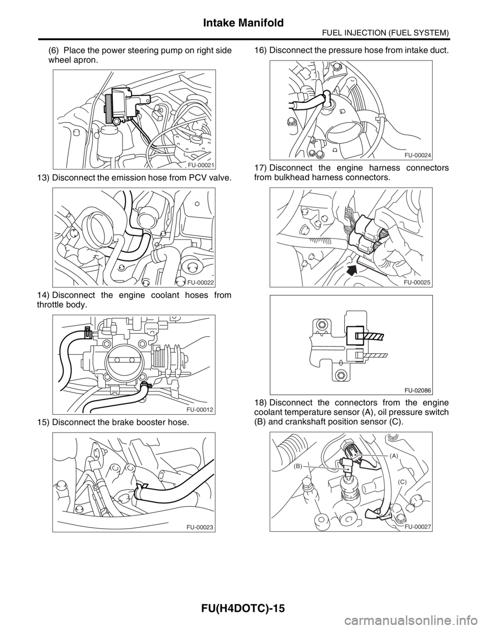
FU(H4DOTC)-15
FUEL INJECTION (FUEL SYSTEM)
Intake Manifold
(6) Place the power steering pump on right side
wheel apron.
13) Disconnect the emission hose from PCV valve.
14) Disconnect the engine coolant hoses from
throttle body.
15) Disconnect the brake booster hose.16) Disconnect the pressure hose from intake duct.
17) Disconnect the engine harness connectors
from bulkhead harness connectors.
18) Disconnect the connectors from the engine
coolant temperature sensor (A), oil pressure switch
(B) and crankshaft position sensor (C).
FU-00021
FU-00022
FU-00012
FU-00023
FU-00024
FU-00025
FU-02086
(A)
(B)
(C)
FU-00027