Page 905 of 2870
ME(H4SO)-36
MECHANICAL
Engine Assembly
(2) Loosen the lock bolt and slider bolt, and
then remove the front side V-belt.
ME(H4SO)-43, FRONT SIDE BELT, REMOV-
AL, V-belt.>
(3) Remove the pipe with bracket.
(4) Remove the bolts which install power steer-
ing pump bracket.
(5) Remove the reservoir tank from bracket by
pulling it upward.
(6) Place the power steering pump on right side
wheel apron.14) Remove the front and center exhaust pipe.
Pipe.>
15) Remove the nuts which hold lower side of
transmission to engine.
16) Remove the nuts which install front cushion
rubber onto front crossmember.
17) Separate the torque converter clutch from drive
plate. (AT model)
(1) Lower the vehicle.
(2) Remove the service hole plug.
(3) Remove the bolts which hold torque con-
verter clutch to drive plate.
(4) Remove other bolts while rotating the en-
gine using socket wrench.
ME-00331
FU-00139
FU-00020
FU-00140ME-00210
ME-00211
ME-00212
Page 940 of 2870
ME(H4SO)-69
MECHANICAL
Cylinder Block
21.Cylinder Block
A: REMOVAL
NOTE:
Before conducting this procedure, drain the engine
oil completely.
1) Remove the intake manifold.
14, REMOVAL, Intake Manifold.>
2) Remove the V-belt.
MOVAL, V-belt.>
3) Remove the crank pulley.
45, REMOVAL, Crank Pulley.>
4) Remove the timing belt cover.
ME(H4SO)-47, REMOVAL, Timing Belt Cover.>
5) Remove the timing belt.
REMOVAL, Timing Belt.>
6) Remove the cam sprocket.
53, REMOVAL, Cam Sprocket.>
7) Remove the crank sprocket.
45, REMOVAL, Crank Pulley.>
8) Remove the generator and A/C compressor with
their brackets.
9) Remove the rocker cover.
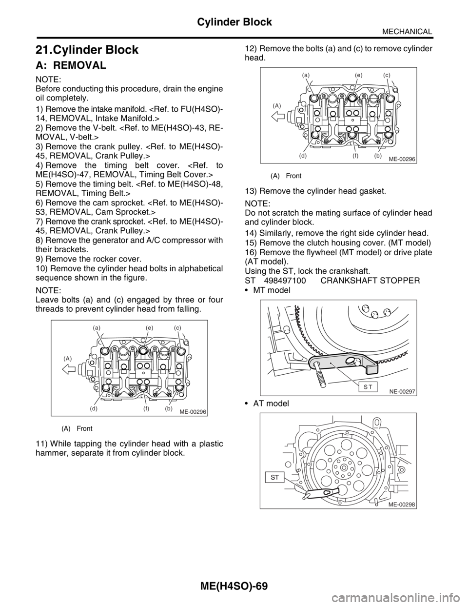
10) Remove the cylinder head bolts in alphabetical
sequence shown in the figure.
NOTE:
Leave bolts (a) and (c) engaged by three or four
threads to prevent cylinder head from falling.
11) While tapping the cylinder head with a plastic
hammer, separate it from cylinder block.12) Remove the bolts (a) and (c) to remove cylinder
head.
13) Remove the cylinder head gasket.
NOTE:
Do not scratch the mating surface of cylinder head
and cylinder block.
14) Similarly, remove the right side cylinder head.
15) Remove the clutch housing cover. (MT model)
16) Remove the flywheel (MT model) or drive plate
(AT model).
Using the ST, lock the crankshaft.
ST 498497100 CRANKSHAFT STOPPER
MT model
AT model
(A) Front
ME-00296
(a)
(b)(c) (e)
(f) (A)
(d)
(A) Front
ME-00296
(a)
(b)(c) (e)
(f) (A)
(d)
NE-00297ST
ME-00298
Page 941 of 2870
ME(H4SO)-70
MECHANICAL
Cylinder Block
NOTE:
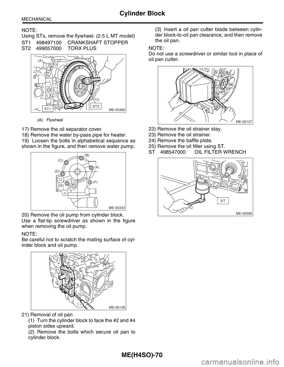
Using STs, remove the flywheel. (2.5 L MT model)
ST1 498497100 CRANKSHAFT STOPPER
ST2 499057000 TORX PLUS
17) Remove the oil separator cover.
18) Remove the water by-pass pipe for heater.
19) Loosen the bolts in alphabetical sequence as
shown in the figure, and then remove water pump.
20) Remove the oil pump from cylinder block.
Use a flat-tip screwdriver as shown in the figure
when removing the oil pump.
NOTE:
Be careful not to scratch the mating surface of cyl-
inder block and oil pump.
21) Removal of oil pan
(1) Turn the cylinder block to face the #2 and #4
piston sides upward.
(2) Remove the bolts which secure oil pan to
cylinder block.(3) Insert a oil pan cutter blade between cylin-
der block-to-oil pan clearance, and then remove
the oil pan.
NOTE:
Do not use a screwdriver or similar tool in place of
oil pan cutter.
22) Remove the oil strainer stay.
23) Remove the oil strainer.
24) Remove the baffle plate.
25) Remove the oil filter using ST.
ST 498547000 OIL FILTER WRENCH
(A) Flywheel
(A)
ME-00382
ST1ST2
ME-00333
(B)
(F) (D)(C)
(A)
(E)
ME-00138
ME-00137
ME-00299
ST
Page 945 of 2870
ME(H4SO)-74
MECHANICAL
Cylinder Block
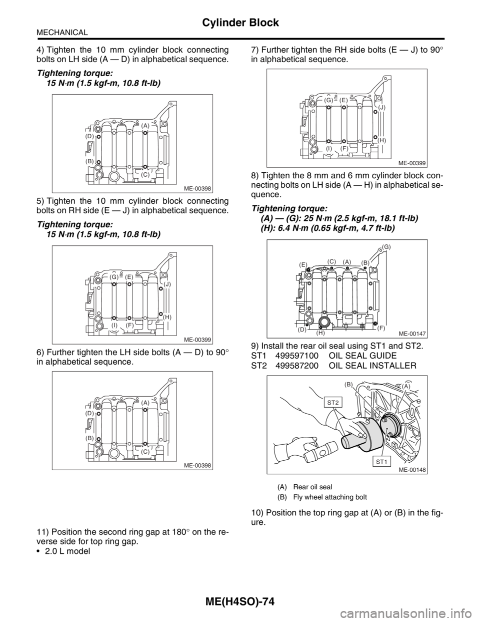
4) Tighten the 10 mm cylinder block connecting
bolts on LH side (A — D) in alphabetical sequence.
Tightening torque:
15 N
⋅m (1.5 kgf-m, 10.8 ft-lb)
5) Tighten the 10 mm cylinder block connecting
bolts on RH side (E — J) in alphabetical sequence.
Tightening torque:
15 N
⋅m (1.5 kgf-m, 10.8 ft-lb)
6) Further tighten the LH side bolts (A — D) to 90°
in alphabetical sequence.7) Further tighten the RH side bolts (E — J) to 90°
in alphabetical sequence.
8) Tighten the 8 mm and 6 mm cylinder block con-
necting bolts on LH side (A — H) in alphabetical se-
quence.
Tightening torque:
(A) — (G): 25 N
⋅m (2.5 kgf-m, 18.1 ft-lb)
(H): 6.4 N
⋅m (0.65 kgf-m, 4.7 ft-lb)
9) Install the rear oil seal using ST1 and ST2.
ST1 499597100 OIL SEAL GUIDE
ST2 499587200 OIL SEAL INSTALLER
10) Position the top ring gap at (A) or (B) in the fig-
ure.
11) Position the second ring gap at 180° on the re-
verse side for top ring gap.
2.0 L model
ME-00398
(A)
(B)
(C) (D)
ME-00399
(E)(G)
(F)(I)
(J)
(H)
ME-00398
(A)
(B)
(C) (D)
(A) Rear oil seal
(B) Fly wheel attaching bolt
ME-00399
(E)(G)
(F)(I)
(J)
(H)
ME-00147
(B)(C)
(D)
(E)
(F)
(G)
(H)
(A)
ME-00148
ST1
ST2
(B)
(A)
Page 950 of 2870
ME(H4SO)-79
MECHANICAL
Cylinder Block
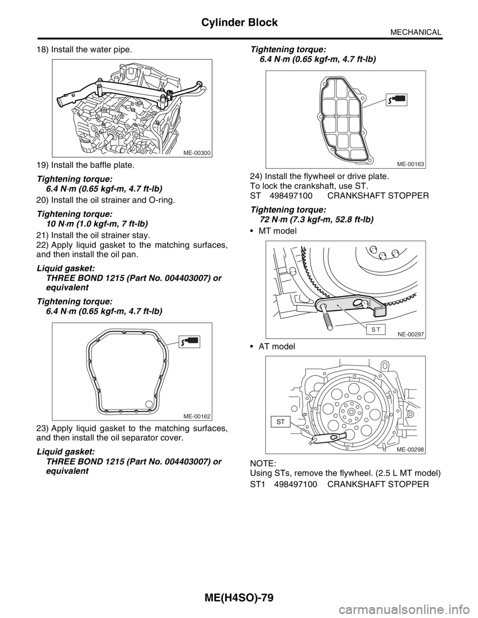
18) Install the water pipe.
19) Install the baffle plate.
Tightening torque:
6.4 N
⋅m (0.65 kgf-m, 4.7 ft-lb)
20) Install the oil strainer and O-ring.
Tightening torque:
10 N
⋅m (1.0 kgf-m, 7 ft-lb)
21) Install the oil strainer stay.
22) Apply liquid gasket to the matching surfaces,
and then install the oil pan.
Liquid gasket:
THREE BOND 1215 (Part No. 004403007) or
equivalent
Tightening torque:
6.4 N
⋅m (0.65 kgf-m, 4.7 ft-lb)
23) Apply liquid gasket to the matching surfaces,
and then install the oil separator cover.
Liquid gasket:
THREE BOND 1215 (Part No. 004403007) or
equivalentTightening torque:
6.4 N
⋅m (0.65 kgf-m, 4.7 ft-lb)
24) Install the flywheel or drive plate.
To lock the crankshaft, use ST.
ST 498497100 CRANKSHAFT STOPPER
Tightening torque:
72 N
⋅m (7.3 kgf-m, 52.8 ft-lb)
MT model
AT model
NOTE:
Using STs, remove the flywheel. (2.5 L MT model)
ST1 498497100 CRANKSHAFT STOPPER
ME-00300
ME-00162
ME-00163
NE-00297ST
ME-00298
Page 951 of 2870
ME(H4SO)-80
MECHANICAL
Cylinder Block
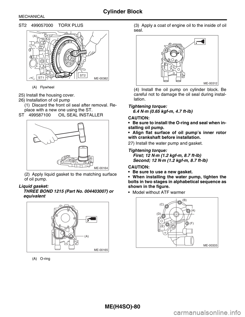
ST2 499057000 TORX PLUS
25) Install the housing cover.
26) Installation of oil pump
(1) Discard the front oil seal after removal. Re-
place with a new one using the ST.
ST 499587100 OIL SEAL INSTALLER
(2) Apply liquid gasket to the matching surface
of oil pump.
Liquid gasket:
THREE BOND 1215 (Part No. 004403007) or
equivalent(3) Apply a coat of engine oil to the inside of oil
seal.
(4) Install the oil pump on cylinder block. Be
careful not to damage the oil seal during instal-
lation.
Tightening torque:
6.4 N
⋅m (0.65 kgf-m, 4.7 ft-lb)
CAUTION:
Be sure to install the O-ring and seal when in-
stalling oil pump.
Align flat surface of oil pump’s inner rotor
with crankshaft before installation.
27) Install the water pump and gasket.
Tightening torque:
First; 12 N
⋅m (1.2 kgf-m, 8.7 ft-lb)
Second; 12 N
⋅m (1.2 kgf-m, 8.7 ft-lb)
CAUTION:
Be sure to use a new gasket.
When installing the water pump, tighten the
bolts in two stages in alphabetical sequence as
shown in the figure.
Model without ATF warmer
(A) Flywheel
(A) O-ring
(A)
ME-00382
ST1ST2
ME-00164
ME-00165
(A)
ME-00312
ME-00333
(B)
(F) (D)(C)
(A)
(E)
Page 967 of 2870

ME(H4SO)-96
MECHANICAL
Engine Noise
23.Engine Noise
A: INSPECTION
NOTE*:
When disconnecting fuel injector connector, the malfunction indicator light illuminates and DTC is stored in ECM memory.
Therefore, carry out the clear memory mode and inspection mode
after connecting fuel injector connector.Type of sound Condition Possible cause
Regular clicking soundSound increases as engine
speed increases. Valve mechanism is defective.
Incorrect valve clearance
Worn valve rocker
Worn camshaft
Broken valve spring
Heavy and dull clankOil pressure is low. Worn crankshaft main bearing
Worn connecting rod bearing (big end)
Oil pressure is normal. Loose flywheel mounting bolts
Damaged engine mounting
High-pitched clank (Spark
knock)Sound is noticeable when
accelerating with an overload. Ignition timing advanced
Accumulation of carbon inside combustion chamber
Wrong spark plug
Improper gasoline
Clank when engine speed is
medium (1,000 to 2,000 rpm).Sound is reduced when fuel
injector connector of noisy cyl-
inder is disconnected.
(NOTE*) Worn crankshaft main bearing
Worn bearing at crankshaft end of connecting rod
Knocking sound when engine
is operating under idling speed
and engine is warmSound is reduced when fuel
injector connector of noisy cyl-
inder is disconnected.
(NOTE*) Worn cylinder liner and piston ring
Broken or stuck piston ring
Worn piston pin and hole at piston end of connecting rod
Sound is not reduced if each
fuel injector connector is dis-
connected in turn. (NOTE*) Unusually worn valve lifter
Worn cam gear
Worn camshaft journal bore in crankcase
Squeaky sound — Insufficient generator lubrication
Rubbing sound — Defective generator brush and rotor contact
Gear scream when starting
engine— Defective ignition starter switch
Worn gear and starter pinion
Sound like polishing glass with
a dry cloth— Loose drive belt
Defective water pump shaft
Hissing sound — Loss of compression
Air leakage in air intake system, hoses, connections or mani-
folds
Timing belt noise — Loose timing belt
Belt contacting case/adjacent part
Valve tappet noise — Incorrect valve clearance
Page 1044 of 2870
LU(H4SO)-16
LUBRICATION
Oil Pan and Strainer
5. Oil Pan and Strainer
A: REMOVAL
1) Set the vehicle on lift arms.
2) Remove the front wheels.
3) Disconnect the ground cable from battery.
4) Remove the air intake duct and air cleaner case.
(Non-turbo model)
Case.>
5) Disconnect the connector from mass air flow
sensor. (Turbo model)
6) Remove the air intake boot and air cleaner upper
cover. (Turbo model)
7) Remove the intercooler (Turbo model)
IN(H4DOTC)-10, REMOVAL, Intercooler.>8) Remove the pitching stopper.
9) Remove the radiator upper brackets.
10) Support the engine with a lifting device and
wire ropes.
11) Lift-up the vehicle.
CAUTION:
When lifting up the vehicle, rise up the wire
rope together.
12) Remove the under cover.
FU-00009
LU-00026
LU-00070
ME-00213
LU-00027
LU-00028